Power balance
When solving electrical problems, you often need to check the correctness of the found values. For this purpose, in the science of TOE, there is a so-called power balance .
Power balance is an expression of the law of conservation of energy in an electrical circuit. The definition of power balance is as follows: the sum of powers consumed by receivers is equal to the sum of powers given by sources. That is, if the EMF source in a circuit supplies 100 W, then the receivers in this circuit consume exactly the same power.
Or
Let's check this relationship using a simple example.
First, let's reverse the circuit and find the equivalent resistance. R2 and R3 are connected in parallel.
Let's find the source current and voltage on R23 using Ohm's law, taking into account that r1 and R23 are connected in series, therefore, the current strength is the same.
Now let's check the correctness using the power balance.
Slight differences in values are due to rounding during calculations.
Using a power balance, you can check not only a simple circuit, but also a complex one. Let's check the complex circuit from the article using the loop current method.
As you can see, regardless of the complexity of the chain, the balance has converged, and should converge in any chain!
Source
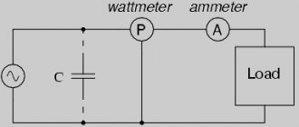
2.10. Power and its components in alternating current circuits
In DC circuits, the load power was determined by the formula: , and for sources: .
In alternating current circuits, if we act by analogy, power can be represented in the form: p = ui, that is, it changes over time (see sections 2.5 and 2.6). If you use complexes, then the power will have the form: .
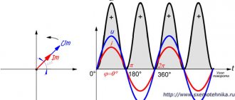
But such a record does not always correctly reflect the processes. In this formula, the dependence of the result on the position of the vectors on the complex plane is observed. So, for the load: ,
if the voltage angle is greater than zero, and the current of such a load lags behind the voltage and if they are located on the complex plane (Fig. 2.13), the scalar product of two complexes is equal to the product of their modules, and the resulting angle is equal to the angle between the current and voltage vectors, which does not work when multiplying complexes:
The angle is not equal to the angle between the current and voltage vectors.
To calculate the total power in alternating current circuits, an artificial technique is used. In the total power formula, instead of the current complex, substitute the complex conjugate current:
or in algebraic form:
If the current complex is equal to: , then the complex conjugate current is found as follows:
The power balance for AC circuits is compiled as follows:
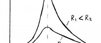
Reactive power in alternating current circuits can be either positive or negative. For inductive loads: , it is greater than zero, and for capacitive loads it is less than zero.
Source
Power balance in AC circuits
Complex power is the product of the complex of the effective voltage value and the conjugate complex of the effective current value.
The sign of the imaginary part of the conjugate complex is changed to the inverse ( ) sign of the given complex number (example: , )).
Let the voltage and current be known on a section of the electrical circuit. The conjugate current is equal to: .
Then the total complex power of this section is equal to:
where is the phase shift between voltage and current.
, [W] – active power of the section,
, [VAr] – reactive power of the section.
The “+” sign in front corresponds to the inductive nature of the resistance, the “–” sign corresponds to the capacitive nature.
When the power balance condition is met, the active and reactive powers of the power sources must be equal to the consumed active and reactive powers.
Source power E.M.F. determined by the formula:
where is the conjugate complex of the current in the branch with the E.M.F. source.
Current source power:
where is the voltage at the terminals of the current source;
– conjugate current of the current source.
Source power E.M.F. enters the balance expression with a “+” sign if the direction of the E.M.F. source and current in this branch coincide; if the directions of E.M.S. source and current do not coincide, then the power of the source E.M.F. negative.
The power of the current source is included in the balance expression with a “+” sign if the source current and the voltage at its terminals are directed towards each other. When the directions of the source current and voltage coincide, the source power is negative.
The active and reactive powers of consumers are equal, respectively:
where is the modulus of the effective value of the current of the i-th branch.
where is the equivalent reactance of the i-th branch.
When the power balance condition is met:
Examples of calculations of single-phase sinusoidal current circuits
Example 6.1
| Given: , , , Determine the currents in the branches, draw up and calculate the power balance for the circuit in Fig. 6.1. |
| Rice. 6.1 |
Solution
For the calculation we will use the loop current method.
The value of the loop current is taken equal to the value of the current source. We create an equation for the loop current:
We express the current from the previous equation:
The current in the third branch is equal to the loop current, . Let's write this current in exponential form of a complex number:
We define the current in the second branch as the algebraic sum of the loop currents passing through this branch:
The total power of the receivers is determined by the formula:
The active power of the receivers in this circuit is determined by the following formula:
The reactive power of receivers is determined by the formula:
The total power released into the system by the sources is determined by the formula:
Performing a power balance confirms the correctness of the problem solution.
Example 6.2
| Rice. 6.2 | Given: , , , , , . For the diagram in Fig. 6.2 calculate the current in the unbranched part of the circuit. Write down. |
Solution
We write the time function in the exponential form of a complex number:
We determine the input resistance of the circuit relative to the terminals of the voltage source:
The instantaneous current value has the form:
Example 6.3
Calculate the currents , , in the circuit of example 6.2 using the graphic-analytical method, construct a topographic voltage diagram combined with a vector diagram of currents.
Solution
The graphoanalytical method of calculation is a combination of the graphical method and the method of proportional recalculation. The method is based on a linear relationship between currents and voltages. Therefore, a vector diagram of voltages and currents, calculated and constructed for one value feeding the voltage circuit, will retain its appearance when the value of this voltage changes. Only the scales of voltages and currents will change on the diagram.
| Let's denote the currents in the diagram. Let's choose the scale: scale for current; scale for voltage. We begin the construction from the point corresponding to the negative polarity of the input terminals, this is point “ e ” (Fig. 6.3). |
| Rice. 6.3 |
We accept the effective value of the current. We lay the vector in the horizontal direction (Fig. 6.4).
We will denote currents and voltages determined using the diagram with one stroke.
We determine according to Ohm’s law for the effective voltage values in the “ ” and “ ” sections of the circuit.
We construct vectors of these voltages. The “ ” section contains a capacitance, the voltage on it lags behind the current by , the “ ” section is resistive - its voltage coincides with the current in phase. The ends of the voltage vectors are designated by the corresponding letters.
The sum of the vectors determines the voltage vector in the section “ c
-e
"
. From the scale diagram we determine the voltage value. Next, according to Ohm's law, we determine the current for the section with the resistor. We construct the current vector taking into account the scale from the end of the vector, taking into account that it is in phase with the voltage. The sum of the vectors gives the current vector in the common branch of the circuit: . From the diagram we determine the effective value. Now we determine the effective values of voltages and . We construct a vector from point C. The voltage leads the current by , because section “ ” is inductive, the voltage is in phase with the current, because section " " contains active resistance.
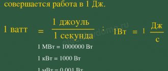
DC power
Hello! This article can be considered the beginning of an acquaintance with electricity. Voltage, current, resistance are the three main quantities on which the basic laws of electrical engineering are based, and these quantities are interconnected by another – power. And to make it easier to get acquainted with electrical engineering, we will consider power in a direct current circuit . The fact is that when calculating in alternating current circuits, quite a lot of conditions appear. However, first things first, and now you can figure it out on your own.
For convenience, I will immediately write the international designations for these four quantities:
U – voltage (V, volts)
R – resistance (Ohm, ohm)
P – power (W, watt – not to be confused with volt, which is denoted by only one letter B)
First, an abstract example to make it easier to understand the terms that I will now use. Let's say there is a store of goods (conventionally, this can be represented as voltage), there is money (conventionally, this will be current), there is a conscience that does not allow you to spend a lot or, on the contrary, whispers that you should spend big (this can be considered resistance) and there is goods purchased or products you carry home (this is power). Actually, this example can explain many laws related to electric current. All indicated quantities are related to each other by Ohm’s law, which states that the current strength in a circuit is directly proportional to the voltage and inversely proportional to the resistance of the circuit, namely:
In an abstract example, the larger the store (voltage) and the less your conscience whispers to you (resistance), the more money you spend (current), and when you carry the purchased product home, you do work (power). Power in a DC circuit is the work done by electricity. Power is the product of current and voltage, and if you substitute the corresponding values instead of current or voltage, you can get a mnemonic:
As you can see, power in a DC circuit is a fairly simple concept if you think about the material a little. Essentially, these are just two formulas with values replaced. What it looks like:
If we now substitute the current formula for the current value in the power formula, we get the following:
This is exactly how the 12 formulas based on Ohm’s law that you see in the mnemonic tablet came about. We have more or less figured out what power is in DC circuits, but there is one more point.
General concept
Electric voltage is defined as the ratio of the work done by the field to transfer a test charge from one given point to another to the size of the potential. When a unit reserve is dislocated, work is performed that is equal to the voltage in the desired area. The total power is obtained by multiplying the work of the electric field for a unit charge by the number of potentials per specific unit of time.
In an alternating electrical circuit, 3 types of power are distinguished:
- active P;
- reactive Q;
- full type S.
In an alternating electricity circuit, the formula for calculating direct current is used only to calculate instantaneous power. This indicator undergoes changes over time and has almost no practical meaning for all other calculations. The power average requires time integration. The instantaneous power is combined over a certain period to calculate the magnitude in the line with periodic changes in the alternating flux strength and sinusoidal voltage.
Conversion rate factor
Power factor is a measure of current consumption in the presence of a reactive component and a distorting load. The meaning of the coefficient differs from the concept of the cosine of the shifted angle. The second concept is characterized by the displacement of the flowing alternating current, voltage, and is used only with a sinusoidal current and force of equal value.
The coefficient is equal to the ratio of the consumed load to its total value. In this case, the work is performed due to the active type of transformation. With sinusoidal current and voltage, the total load is the sum of the reactive and active forms. The active load is equal to the average product of current and voltage and cannot be higher than the product of similar root-mean-square dimensions. The power coefficient is shown in the range from 0 to 1 or set as a percentage from 0 to 100.
How to draw up a power balance
The law of conservation of energy states that energy does not disappear anywhere. She only changes one type to another, saving her number. The law is also objective for electrical circuits, therefore the energy given off by the sources is equal to the energy consumed in the resistors. Hence the equality of expressions for the powers of the sources and the powers in the resistances follows, which is called the power equilibrium equation. Drawing up this equation is a significant task that allows you to check the correctness of calculations of currents and voltages in an electrical circuit
Instructions
1. Determine the power of all sources of the electrical circuit. Power supplied by voltage sources Pu = EI, where E is the effective value of the emf of the source, and I is the value of the current flowing through this source.
2. Find the algebraic sum of the powers supplied by the sources. If the actual (correct) direction of the current through the source coincides with the direction of the EMF, then the power of such a source is positive. If the direction of the current through the source is opposite to the direction of the EMF, then the power of such a source is negative. To find the algebraic sum of powers, add up the correct powers and subtract all negative powers of the sources from the resulting sum.
3. Determine the powers in resistors. Power in resistive resistance Рн = (I^2)*R, where I is the current in the resistor, R is its resistance. The power in the resistor is invariably positive because the power spent on heating does not depend on the direction of the current.
4. Find the arithmetic sum of the powers dissipated in the resistors of the circuit. To find this sum, add up the detected values of the powers consumed across the entire resistor.
5. Compare the sum of powers supplied by the sources with the sum of powers consumed by the resistances. If the electrical circuit is calculated correctly, both values of the resulting amounts will be equal. The equilibrium condition is fulfilled. The resulting equality is the power equilibrium equation for a given electrical circuit.
Helpful advice When calculating the power balance, a source with an arbitrary voltage waveform must be replaced with a source of continuous voltage.
Source of the article: https://jprosto.ru/kak-sostavit-balans-moschnostey/
Practical application and correction
If a load with a current leading or lagging behind the voltage by some angular value is connected to a socket with a sinusoidal voltage of 50 Hz and 230 V, then increased power will be generated on the active internal coil. This means that when operating under such conditions, a lot of heat is generated, and the power plant removes it in an increased amount compared to the use of a resistive load.
Efficiency and power coefficients differ from each other. The power indicator does not affect the consumption of the receiver connected to the network, but it changes the energy losses in the underwater wires and places where energy is generated or converted. In the house, the electric meter does not respond to the manifestation of power, since only the energy that powers the appliances is paid for.
Efficiency affects the consumed active load. For example, an energy-saving lamp consumes one and a half times more electricity than a similar incandescent device. This indicates a high efficiency of the first lamp. But the load indicator can be low and high in both options.
The correction consists of bringing the consumption of a device with a low power factor to standard values when powered from an AC power circuit. Technically, this is accomplished by using an effective circuit on the input device, which helps to evenly use the phase power and eliminates overload of the neutral wire. At the same time, surges in consumer current at the top of the supply voltage sinusoid are reduced.
The reactive load is adjusted when a reverse-acting element is included in the main line. For example, in an AC motor, a capacitor is placed parallel to the supply line to compensate for the action. An active or passive corrector system is used when the used current changes during the oscillatory period of the supply voltage to convert the coefficient. A simple example is a series connection of a choke. In this case, the end devices consume current disproportionately to harmonic distortion. The coil smooths out the wave impulses.
Source
Error in power balance
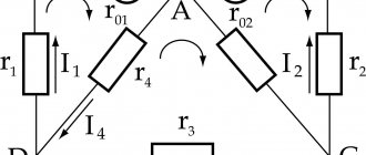
I made a calculation using the loop current method. The direction of the loop currents coincides with the direction of bypassing the loops.
Found the loop currents: I22 = 1.83 A I33 = 2.59 A I44 = -0.57 A
Question: does it look real?
It is necessary to calculate the measurement error (using the example). It is not clear to me from the example how the error was found. We need to calculate the measurement error. (using the example) It is not clear to me from the example how the error was found.
Equipment balance problem After casting is completed in the foundry, the casting must be transferred to the workshop where it takes place.
there is not enough money on the balance # Place a bet if (isset($_POST) and isset($_POST) and isset($_POST))
There is no money on the balance sheet, but there is Internet! In general, I went to another city, reinstalled Windows there, used the local network (enter the password there.
Message from Gambit_88
OldFedor
, I took up the calculation using the method of nodal potentials relative to node D. I received currents that were quite different from those previously calculated. Intrinsic conductivity: GAA = 1/R2 + 1/R3 = 0.17 GBB = 1/R2 + 1/R4 + 1/R5 = 0.246 GCC = 1/R4 + 1/R6 = 0.15 Total conductivity: GAB = GBA = -1/R2 = -0.076 GAC = GCA = 0 GBC = GCB = -1/R4 = -0.076 Nodal currents: JAA = -E2/R2 + J1 = -0.03 JBB = E2/R2 = 3.03 Here question: JCC = or 0 - J1, i.e.
-3
?
Added after 32 minutes
I tried both values, but the results in both cases are far from clear:
| I1 | I2 | I3 | I4 | I5 | I6 | I7 | |
| 3 | 2,29 | 0,72 | -0,65 | 1,64 | 0,66 | 1,2 | |
| -3 | 3 | 2,65 | 0,35 | -1,84 | 0,81 | -1,18 | 15,62 |
Added after 10 minutes
I1 = J1 I2 = (φA - φB + E2) / R2 I3 = (φA - φD) / R3 I4 = (φC - φB) / R4 I5 = (φB - φD) / R5 I6 = (φC - φD) / R6 I7 = φD - φC + E7
And, naturally, the balance in this case is also far from what was calculated above.
Source