Story
Of course, at first there were experiments by the English physicist Michael Faraday with coils, which he used to understand how the distance between them affects electromagnetic induction. As a result of these experiments, the first transformer appeared. 100 years later, Soviet engineer, scientist and inventor Lev Theremin, creator of one of the first electromusical instruments, the theremin, created an endovibrator - a listening device that operates without a power source. It is believed that the endovibrator, which was long located in the residence of the US Ambassador to the USSR, was the forerunner of radio frequency identification (RFID) devices because it was a passive radio transmitting device that began to work when irradiated by an external radio transmitter located nearby. The endovibrator was a volumetric resonator with a membrane, in which natural oscillations were excited when irradiated with a radio signal with a frequency of 330 MHz. The membrane resonator acted as a condenser microphone. The membrane served as one of the plates of the capacitor, which modulated the natural frequency of the circuit. The resulting frequency-modulated signal was emitted and picked up by a radio receiver also located nearby. The endovibrator hung on the wall in the ambassador’s office for a long time. Everyone saw it, but only seven years later they discovered it and understood how it works.
Faraday coils on display at the Michael Faraday Museum in London
Modern RFID devices do the same thing. RFID readers “irradiate” passive RFID tags with an electromagnetic signal in the radio frequency range and the tags respond by transmitting information contained in their memory or received from external sensors (possibly from microphones, but most often these are thermometers or barometers). The closely spaced coils of the RFID tag and the RFID receiver work together to form a coreless transformer that provides inductive coupling to supply energy to the tag and to transfer information between the tag and the receiver. Since passive RFID tags do not contain batteries, their service life is limited only by the physical aging of the elements.
Calculation methods
There are several basic ways to determine the inductance of a coil. All formulas that will be used in the calculations can be easily found in reference books or on the Internet. The whole calculation process is quite simple and will not be difficult for people with basic mathematical and physical knowledge.
You might be interested in the principle of operation of a thyristor, purpose and connection diagram
Through current
This calculation is considered the simplest way to determine the inductance of a coil. The formula through current follows from the term itself. What is the inductance of the coil can be determined by the formula: L=Ф/I, where:
- L - circuit inductance (in Henry);
- F is the magnitude of the magnetic flux, measured in webers;
- I is the current strength in the coil (in amperes).
This formula is only suitable for a single-turn circuit. If the coil consists of several turns, then instead of the magnetic flux value, the total flux (total value) is used. When the same magnetic flux passes through all the turns, then to determine the total value it is enough to multiply the value of one of them by the total number.
Finite Length Solenoid
The solenoid is a thin long coil, where the thickness of the winding is significantly less than the diameter. In this case, calculations are carried out using the same formula as through current strength, only the magnitude of the magnetic flux will be determined as follows: Ф=µ0NS/l, where:
- µ0 is the magnetic permeability of the medium, determined from lookup tables (for air, which is taken by default in most calculations, it is equal to 0.00000126 henry/meter);
- N is the number of turns in the coil;
- S is the cross-sectional area of the coil, measured in square meters;
- l is the length of the solenoid in meters.
The self-induction coefficient of the solenoid can also be calculated based on the method for determining the energy of the magnetic flux of the field. This is a simpler option, but it requires some quantities. The formula for finding inductance is L=2W/I 2, where:
- W is the magnetic flux energy, measured in joules;
- I is the current strength in amperes.
Toroidal core coil
In most cases, a toroidal coil is wound on a core made of a material with high magnetic permeability. In this case, to calculate the inductance, you can use the formula for a straight solenoid of infinite length. It has the following form: L=N µ0 µS/2 πr, where:
- N is the number of coil turns;
- µ—relative magnetic permeability;
- µ0—magnetic constant;
- S is the cross-sectional area of the core;
- π is a mathematical constant equal to 3.14;
- r is the average radius of the torus.
You may be interested in this Technical characteristics and types of electronic dimmers
Long conductor
Most of these quasi-linear conductors have a circular cross-section. In this case, the value of the self-induction coefficient will be determined by the standard formula for approximate calculations: L= µ0l (µelnl/r+ µi/4)/2 π. The following notations are used here:
- l is the length of the conductor in meters;
- r is the radius of the wire cross-section, measured in meters;
- µ0—magnetic constant;
- µi is the relative magnetic permeability characteristic of the material from which the conductor is made;
- µe is the relative magnetic permeability of the external environment (most often the value for vacuum is taken to be 1);
- π—pi number;
- ln is the notation for logarithm.
RFID and NFC - what's the difference
So what are RFID and NFC? Both are closely related methods of transmitting information that have numerous areas of application. Examples include inventory management, contactless payments, exchange of contact information, photos and videos, electronic payment of toll roads and bridges, and much more. Radio Frequency Identification (RFID) is a technology that uses electromagnetic fields to identify and track the movement of tags attached to various objects. Near-Field Communication (NFC) is a technology based on existing radio frequency identification standards that allows communication between two electronic devices located nearby at a distance of less than 10 cm. Typically these are two smartphones, or a reader and a smartphone, or a smartphone and an RFID tag. To organize communication using NFC, a range with an average frequency of 13.56 MHz is used. The same frequency is standardized for RFID devices.
RFID tag antenna chip and coil
Radio Frequency Identification (RFID)
Allows one-way or two-way communication between RFID tags and the RFID receiver. Tags can be passive (without their own power source), active (with their own battery) and semi-passive (also with a battery). Receivers have their own power supply and can be passive (operating in tag-reading mode only) and active (they can not only read, but also transmit information to tags). RFID tags can be read over long distances, up to 200 meters without a direct line of sight between the reader and the tag. Therefore, they can be used, for example, to handle baggage at the airport. RFID uses several radio frequency bands, shown in the table below. Communication between the reader and tags is carried out using standardized protocols. Different protocols are used for different frequency ranges.
| RFID frequency range | Scan distance | Examples of technology application |
| 120-150 kHz (low frequencies, LF) | up to 10 cm | Automotive immobilizers, RFID tags for animals, industrial applications |
| 13.56 MHz (treble, HF) | Up to 1 m | Product movement tracking, smart tags, near-field communication (NFC), access control to premises |
| 433 MHz (ultra high frequencies, UHF) | 1–150 m (active tags) | Monitoring the movement of personnel and vehicles, monitoring sensor data |
| 860–960 MHz (ultra high frequencies, UHF) | 1–12 m (depending on tag type) | Tracking the movement of boxes and pallets with cargo, accounting, control and registration in industry, tags for transmitting information read from sensors, identification in livestock farming, anti-theft and anti-theft devices |
| 2.45 GHz (UHF) | 1–100 m (active tags) | Industrial applications, key tags, sensor tags, wrist strap tags for people tracking |
| 3.1–10 GHz (ultra high frequencies, microwave) | Up to 200 m (active tags) | Real-time product monitoring systems, accounting of material assets |
Near Field Communication (NFC)
operates in the 13.56 MHz frequency range and is an extension of the RFID standard and protocols. In this regard, many of the physical properties of NFC coincide with the properties of high-frequency RFID devices. NFC allows two-way communication between two closely located (less than 5 cm apart) electronic devices, one of which is usually a smartphone, and the other is a smartphone, payment card reader, or NFC tag. NFC combines a smart card interface and a smart card reader into one device. Both RFID and NFC high frequency communications operate in the same frequency range with a center frequency of 13.56 MHz. Unlike RFID, which works well at distances of 100 m or more, NFC works at a maximum distance of only 10 cm.
Examples of communication between two mobile phones include exchanging files using the Android Beam app, pairing between two Bluetooth devices and establishing a connection between them without the need for passwords. There are many examples of communication between a mobile phone and a tag that can be easily programmed from the phone: calling a social networking site, launching the Google Maps application or another application with maps and routes to return home, opening a link to a video, sending an email message, organizing a poster link with online objects and much more. Perhaps one of the main uses of NFC is to accept payments by establishing a connection between a mobile phone and a payment terminal. A phone with NFC capabilities can open and close doors. Please note that at the time of writing this article (summer 2021), Apple devices only supported accepting payments. Everything else is not yet available for Apple phones.
Honda car ignition key: 1 - lithium battery, 2 - remote control housing with RFID transponder, 3 - rear wall of the key, 4 - front wall of the key housing with a metal key, 5 - sealing gasket, 6 - Honda key assembly, 7 - front cover of the control panel with buttons, 8 - printed circuit board of the remote control, 9 - enlarged image of the printed circuit board, 10 - quartz oscillator, 11, 15, 16, 17 - buttons, 13 - inductor 2.63 mH 25 Ohm, used as a transponder coil, 14 - remote control and RFID transponder chip
The table below shows the differences between high frequency RFID and NFC technologies
| Protocol Features | HF RFID | NFC |
| Operating frequency | 13.56 MHz | 13.56 MHz |
| Communication type | One-sided | Double sided |
| Double sided | ISO 14443, 15693, 18000 | ISO 14443 |
| Scan distance | Up to 1 m | Up to 10 cm |
| Ability to scan multiple tags simultaneously | Yes | No |
Main settings
The main characteristics of the inductor include:
- Inductance.
- Current strength (to select a suitable element during repair and design, this must be taken into account).
- Loss resistance (in wires, in core, in dielectric).
- Quality factor is the ratio of reactance to active resistance.
- Parasitic capacitance (capacitance between turns, in simple terms).
- Temperature coefficient of inductance - the change in inductance when an element is heated or cooled.
- Temperature quality factor.
Types of RFID tags
There are three types of RFID tags: active, passive and semi-passive. Active and semi-passive tags use batteries to power their chips. They are more expensive than passive tags, but they have more useful properties. In particular, active tags use their own power source to power a transmitter that creates electromagnetic waves, which can significantly increase the communication range between the tag and the reader.
Active tags
Because active tags contain batteries, they can store more information and provide a longer communication range. They can transmit a radio signal that can be received at a distance of up to 100 meters. Due to this feature, active RFID tags are convenient for organizing the accounting of material resources. The battery life of active RFID tags is up to 10 years. Due to the design of tags, they are usually not replaceable, and at the end of their service life the entire tag must be replaced.
Active RFID tags can operate in two modes: transponder and beacon. To increase battery life, the transponder tag “listens” to the signal from the reader and turns on the transmitter only in cases where such a signal is available. On the other hand, tag beacons turn on the transmitter, for example, once every 10 seconds, trying to send the necessary information. Active tags often contain various sensors and allow you to read information about humidity levels, temperature, pressure and other environmental parameters. The design of active RFID tags is often much more complex than the design of passive tags - which is why active tags are more expensive than passive ones.
Passive tags
An NFC key for a hotel room, which simultaneously functions as a general light switch and various household appliances. To turn on the power, the guest must enter the room and insert the key card into the switch
Unlike active RFID tags, passive tags are very simple and consist of just two components: a coil-shaped antenna and an integrated circuit chip. The reader activates its coil, which sends electromagnetic energy to the tag's coil. If the tag is in the read range, both coils form a transformer, which provides an inductive coupling used to communicate and power the tag itself - the same principle that wireless charging works on smartphones. The alternating current taken from the tag antenna is rectified and used to power the tag chip, which sends a signal with useful information back to the coil. This information is read by the reader coil.
There are two types of passive RFID tags: RFID stickers and hard type tags. Thanks to a layer of adhesive on the back of the tag, they can be placed anywhere, for example, on library books, to organize the accounting of the library collection. “Hard” tags are reliable in operation and are made of glass, plastic, metal, ceramics, rubber and other materials. Passive RFID tags are thinner and cheaper than active tags and last a lifetime because they do not have a battery. Passive low frequency RFID tags are used for microchipping animals. They are enclosed in a glass capsule slightly larger than a grain of rice and can be used on any cat or dog whose owners are concerned about the possible loss of their pets.
Payment terminal of the PRESTO public transport fare payment system in Ontario, Canada
Semi-passive tags
Semi-passive RFID tags are typically used to monitor sensors or the operation of various equipment by reading various output data, such as the operation of switches (on-off) or valves (open-closed). The principle of their operation is similar to the principle of passive tags. The signal from the reader causes the tag to respond. The battery of a semi-passive tag is used to power electronic circuits that are used to read information from various sensors even if the tag is not being interrogated by the reader. If the tag sends information to the reader, it transmits not only information from the sensors, but also its serial number.
Ideal and real inductors
For ideal inductors, when connected to a sinusoidal voltage source, the current lags in phase with the voltage by p/2, inductive reactance RL
= w
L
, where
L
is inductance (self-inductance coefficient).
As in the case of capacitors, in real coils the phase shift between current and voltage is slightly less than p/2 - by the amount d
, due to energy losses in the coil when alternating current flows through it - mainly due to heating of the winding wire.
The value is called the quality factor of the coil
. For a series equivalent circuit, for a parallel circuit.
In some cases, especially at high frequencies, more complex equivalent circuits are used, which additionally take into account the inductance of the capacitor leads and the interturn capacitance of the coils.
Low Frequency AC Measuring Bridges
Capacitances and dielectric loss tangents of capacitors, inductance and quality factor of coils can be measured using various bridge circuits. Consider the diagram of a four-arm bridge:
Its arms can contain active resistances, capacitances and inductances and are characterized by impedances (complex resistances). WITH
The circuit is powered by alternating sinusoidal voltage. The condition for the balance of the AC bridge (i.e., the current of the AND indicator being equal to zero) is similar to the condition for the balance of the DC bridge (see work No. 10):
| (5) |
The choice of a specific bridge circuit depends on what equivalent circuit we want to represent the capacitor or inductor under study. For a series equivalent circuit of a capacitor, it is convenient to use a bridge of the following type:
Here R
- graduated (equipped with a scale) variable resistor, C - graduated capacitor with minimal losses (with an air dielectric). Condition (5) for this scheme will be written as:
| or | (6) |
For two complex numbers to be equal, it is necessary that their real and imaginary parts be equal, respectively. Therefore, equality (6) splits into two:
| R X R 2 = RR 1 and | (7) |
From these expressions we obtain two bridge balance conditions that must be met simultaneously:
| (8) |
| (9) |
Model inductors are almost never used in AC bridges, because it is difficult to make a coil with very low losses. To measure the parameters of coils in a series equivalent circuit, a bridge of the following type is usually used:
RFID devices implanted into the human body
Human RFID tags are usually a passive RFID transponder containing an integrated circuit chip (colloquially called a chip by lazy journalists) in a glass capsule. The tags are implanted subcutaneously in a person's arm or other part of the body and usually contain a unique identification number that can be linked to information in a database containing information about identity, legal problems, medical history, medications taken and so on. VeriChip Corporation began producing RFID implants back in 2002, and in 2004 their devices were certified by the US Food and Drug Administration (FDA).
Future applications of passive RFID tags implanted in the human body:
- Providing data for electronic systems for storing medical information about patients
- Monitoring patients in hospitals
- Monitoring the time patients take medications in hospitals
- Medical Device Management
- Possibility of retrieving medical information during emergency medical care
- Helping disoriented patients with Alzheimer's disease
- Personnel location control
- Search for lost children
- Convenience of opening doors, managing printers, unlocking computers in offices
Of course, there are many problems associated with human implants, including the possible occurrence of tumors at the site of injection of the tracer, unwanted migration of the tracer in the body; possible incompatibility of tags with devices operating on the principle of magnetic resonance, as well as risks associated with security and privacy.
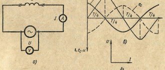
Graph of current and voltage in a circuit versus time
Graphically, the dependence of the current in the circuit and voltage over time looks like this:
Graph of current and voltage in a circuit versus time
As you can see, the current and voltage sinusoids do not coincide: the first is shifted relative to the second by an angle of 900 or ¼ cycle to the right, that is, it lags behind it. This phenomenon is called phase shift.
Contactless communication (NFC)
It appears that in the future, an NFC-enabled phone will be used instead of a wallet for loyalty cards and credit cards. So what is NFC? This is a wireless communication technology over a short distance (up to 10 cm) at a high frequency (13.56 MHz), allowing data exchange between two electronic devices, one of which is usually a smartphone, and the other is an NFC tag, contactless card or reader. Like other RFID technologies (and NFC is part of these technologies), NFC uses electromagnetic induction between two loop antennas when two devices exchange information on the unlicensed ISM (Industrial, Scientific and Medical) high-frequency band in most countries. medical) with an exchange rate of 100–400 kbit/s. The connection is usually established in less than a second, and it takes 1-5 seconds to transfer a 40-kilobyte image. The great convenience of NFC is that it can be used in conjunction with Bluetooth to pair two devices without a password.
Due to the fact that the ISM band used for NFC is between the broadcast shortwave bands of 22 meters (13.57-13.87 MHz) and 25 meters (11.6-12.2 MHz), the communication audio between the smartphone and NFC and a passive tag can be easily heard on a regular shortwave broadcast receiver if you place the phone with the tag near the antenna.
There are three NFC operating modes:
- Direct communication mode between two devices that can operate in NFC mode; for example, it could be two smartphones that communicate with each other.
- Read and write - a mode in which an active NFC device, usually a smartphone, reads information from a passive NFC device (usually an NFC tag); The smartphone can also write information to the tag.
- Payment card emulation is a mode in which an NFC device, usually a smartphone, acts as a contactless card; this allows you to pay for purchases in stores or pay for travel on public transport by bringing it closer to the payment terminal
NFC antenna under the glass back wall of the Xiaomi Mi5 smartphone, which was used for experiments in preparing this article
Using these three operating modes, NFC allows users to transfer information from one smartphone to another, pay for purchases by simply holding the smartphone to a payment terminal, or use the smartphone as an electronic ticket on public transport in a similar way. NFC devices are also used when communicating on social networks, as they allow you to easily exchange contact information by touching one NFC phone to another NFC phone.
It is clear that the ability to use NFC devices to communicate on social networks is increasingly being used to promote goods and services. For example, visitors can touch their phone to NFC tags or simply place the phone on a table with NFC tags attached in a restaurant or bar, and information about their location will be immediately updated on social networks. With just a swipe of their phone, shoppers can post to their Facebook or Twitter accounts about items they like in the store. NFC tags will allow customers to upload information about store hours and location and quickly share it with their friends.
Using an NFC phone, it is easy to check the operation of the biometric passport chip. This can be done, for example, before going on vacation abroad, to be sure that the electronic passport is functioning correctly (isn’t it a somewhat strange combination - a faulty passport?). All you need to do is download the ReadID - NFC Passport Reader application from Google Play (apple phone users, please do not worry - their devices do not yet support all the NFC modes described here, except for payment for services). Take a photo of the machine-readable area of the passport with your phone, then attach the passport to the phone and read the contents of the passport microcircuit. That's all. The application will show you your photo and all the information obtained from the chip. This information is stored in the electrically erasable programmable ROM (EEPROM) of the passport chip. To read passport information, you must first enter the date of birth, date of issue and passport number into the microchip. Some applications allow you to enter this information manually. In our example, it is entered by photographing the machine-readable area with a phone camera. If a passport is scanned, for example, at an airport, then the cryptographic signature stored in the chip must also be checked there. According to some reports, not all airports actually carry out such verification yet, which means that sometimes you can travel with a fake digital passport.
Inductor in a DC circuit.
So, first of all, let's figure out what happens in the coil itself when current flows. If the current does not change its value, then the coil has no effect on it. Does this mean that in the case of direct current the use of inductors should not be considered? But no? After all, direct current can be turned on/off, and it is at the moments of switching that all the interesting things happen. Let's look at the circuit:
In this case, the resistor acts as a load; in its place there could be, for example, a lamp. In addition to the resistor and inductance, the circuit includes a DC source and a switch with which we will close and open the circuit. What happens the moment we close the switch?
The current through the coil will begin to change, since at the previous moment in time it was equal to 0. The change in current will lead to a change in the magnetic flux inside the coil, which, in turn, will cause the occurrence of EMF (electromotive force) of self-induction, which can be expressed as follows:
The occurrence of EMF will lead to the appearance of an induced current in the coil, which will flow in the direction opposite to the direction of the power source current. Thus, the self-induced emf will prevent current from flowing through the coil (the induced current will cancel the circuit current due to the fact that their directions are opposite). This means that at the initial moment of time (immediately after closing the switch), the current through the coil I_L will be equal to 0. At this moment in time, the self-induction emf is maximum. What will happen next? Since the magnitude of the EMF is directly proportional to the rate of change of current, it will gradually weaken, and the current, accordingly, on the contrary, will increase. Let's look at graphs that illustrate what we've discussed:
In the first graph we see the input voltage of the circuit - initially the circuit is open, but when the switch is closed, a constant value appears. In the second graph we see a change in the magnitude of the current through the inductor. Immediately after closing the switch, the current is absent due to the occurrence of self-induction EMF, and then begins to gradually increase.
The voltage on the coil, on the contrary, is maximum at the initial moment of time, and then decreases. The voltage graph across the load will coincide in shape (but not in magnitude) with the current graph through the coil (since in a series connection the current flowing through different elements of the circuit is the same). Thus, if we use a lamp as a load, they will not light up immediately after closing the switch, but with a slight delay (in accordance with the current graph).
A similar transient process in the circuit will be observed when the key is opened. A self-inductive emf will arise in the inductor, but the induced current in the event of an open circuit will be directed in the same direction as the current in the circuit, and not in the opposite direction, therefore the stored energy of the inductor will be used to maintain the current in the circuit:
After the switch is opened, a self-induction emf occurs, which prevents the current through the coil from decreasing, so the current does not reach zero immediately, but after some time. The voltage in the coil is identical in shape to the case of closing the switch, but opposite in sign. This is due to the fact that the change in current, and accordingly the self-inductive emf in the first and second cases, is opposite in sign (in the first case, the current increases, and in the second it decreases).
By the way, I mentioned that the magnitude of the self-induction EMF is directly proportional to the rate of change of current, so the proportionality coefficient is nothing more than the inductance of the coil:
At this point we finish with inductors in DC circuits and move on to AC circuits .
Identity theft using RFID devices
Data read by mobile phone using Credit Card Reader mobile application
In preparation for this article, I performed a simple test: I downloaded the Credit Card Reader app from Google Play and held my phone against a wallet that contained unused credit cards. Information from one of the cards appeared on the phone: my first and last name, the name and number of the credit card, the expiration date of its use, the name of the organization that issued the card and a list of the last ten transactions. It is clear that with the help of more serious equipment (a more powerful transmitter and a good, highly sensitive receiver), this information can be obtained not only by applying the device to the wallet, but also at a short distance, maybe half a meter from the wallet. Of course, this equipment will not be able to read the PIN or three-digit code on the back of the card. However, a thief can use information about such a card to make purchases in some online stores, since not all sellers include the option to verify the three-digit code. Some people turn it off for the convenience of customers. No comments needed.
Measurement options
The inductance of a coil in physics is determined by performing calculations. However, this value can not only be calculated, but also measured. This is done using a direct or indirect method.
Direct method
To measure the inductance of a coil using this method, it is necessary to use special bridge or direct-indicating devices. With their help, you can obtain the most accurate data that will help you select the required coil for the circuit.
The procedure for carrying out measurements includes the following steps :
- A coil is connected to the direct indicating device.
- After this, the measurement ranges are gradually changed. This is done until the result obtained is approximately in the middle of the interval.
- The result obtained is recorded and calculated taking into account the division value of the device, as well as the coefficient corresponding to the position of the switch.
The direct measurement method can also be used to determine inductance using a bridge device. It has a more accurate scale, so it allows you to obtain reliable data.
The measurement is performed by performing the following actions:
- The switched-on bridge device is connected to a coil, the inductance of which must be determined.
- Similar to a direct indicating device, the measurement intervals are switched.
- After each such action, the handle of the bridge balancing regulator is alternately moved to one and the other limit position.
- Once you have determined the range within which the bridge will be balanced, you can proceed further.
- At the next stage of measurement, the dial indicator is gradually moved.
- After the sound disappears from the speaker of the device, it is necessary to record the indicators.
- They are then calculated in accordance with the scale division price and the provided coefficient.
You may be interested in Features of measurement in lumens and watts
Indirect definition
In order to measure the self-induction coefficient, it is necessary to carry out several preparatory measures. First of all, you need to assemble the measuring circuit according to the standard circuit, and also prepare all the necessary devices (sinusoidal voltage generator, frequency meter, as well as a milliammeter and voltmeter designed for alternating current).
The procedure for determining the parameter:
- A voltmeter is connected in parallel to the generator output. It must be switched to a mode in which the upper limit value corresponds to a voltage of 3-5 volts.
- The frequency meter is connected in the same way.
- The second chain is assembled separately. It connects a milliammeter and a coil in series, the inductance of which needs to be determined.
- Then both circuits are connected in parallel to each other.
- The connected generator is set to generate sinusoidal voltage.
- By changing the frequency, they achieve such operation of the devices that the voltmeter will show approximately 2 volts. In this case, the current on the milliammeter will gradually decrease.
- After this, the frequency meter handle is moved to the position corresponding to the measurement frequency.
- Once these steps are completed, the values can be captured.
The obtained data is converted into SI, and then all the necessary calculations are performed. The first step is to determine the inductive reactance. To do this, the values of the devices are substituted into the following relationship: X = U/I, where U is the voltage and I is the current. The result of the calculations will be expressed in ohms.
After this, the inductance is calculated using the formula L=X/2 πF. It uses the following conventions:
- X is inductive reactance;
- π is a mathematical constant (approximately 3.14);
- F is the frequency in hertz at which the measurements were taken.
Inductance is an important physical parameter that allows you to determine the magnetic properties of an electrical circuit. By measuring it accurately and correctly carrying out the required calculations, you can obtain reliable data that will be needed when choosing a coil.
Applications for smartphones, NFC tags and cards
If you use one of the many apps available on Google Play, you can encode NFC tags to perform various tasks, such as
- Change the operating modes of the GPS navigator, Wi-Fi and Bluetooth on your smartphone (turn it on or off).
- Change sound and volume settings (ringer, quiet, loud, vibration only, notification sound, system sounds and alarm volume, vibration on and off).
- Change display settings, such as brightness, auto rotation, turn-on time, and others.
- Interaction with social networks and social media, for example, you can quickly post a photo to a blog.
- Send a message by email or text.
- Open and close applications, open URL.
- Call someone.
- Create various other tasks for NFC tags.
Operating principle of near-contact communication: 1 - NFC reader processor chip, 2 - reader, 3 - NFC tag, 4 - load modulator, 5 - NFC tag chip, 6 - inductive coupling, 7 - data is sent to the load modulator
What happens if you bring your phone with NFC enabled closer to the NFC tag? Suppose you are getting ready to go to bed and touch your phone to the “Alarm Clock” label stuck on your bedside table. The phone periodically activates the NFC chip, which sends a 13.56 MHz AC signal to the loop antenna on the back of the phone. The antenna produces a weak electromagnetic field. This field induces an alternating current in the NFC tag's loop antenna, which is rectified and charges the tag's capacitor. The energy stored in the capacitor is used to power the tag chip, which in turn also generates an alternating current that contains the command to turn on the alarm clock on the phone. The smartphone chip detects the electromagnetic field of the NFC tag loop antenna and decodes the received information. After decoding, the phone runs an alarm program that turns it on.
NFC tag
Alternatives to NFC technology
All payment terminals are still capable of reading cards with magnetic stripes. An alternative to NFC technology is Magnetic Secure Transmission (MST), which appeared in LG Electronics phones in June 2021 and will soon appear in Samsung phones. A phone with MST equipment emulates the magnetic stripe on any payment card. Instead of swiping the card across a reader, the phone sends a "magnetic signal" in the form of a changing magnetic field, which is read by the magnetic head of the payment terminal. This technology can be used on all existing payment terminals without any changes on the part of merchants. To make a payment, a smartphone with a chip and an MST coil generates an alternating magnetic field with a strength sufficient to be read by the magnetic head of a payment terminal at a distance of 8 cm. Before you start paying with your phone, the user must enter information about their payment cards into it. As a result of entering card information, the phone turns into a digital wallet.
Author of the article: Anatoly Zolotkov
Inductive reactance in an AC circuit
One of the main characteristics of electrical circuits is resistance, which can be active or reactive. Typical representatives of active resistance are considered to be ordinary consumers - lamps, incandescent lamps, resistors, heating coils and other elements in which electric current performs useful work.
Reactive includes inductive and capacitive reactance, located in intermediate electricity converters - inductive coils and capacitors. These parameters must be taken into account when performing various calculations. For example, to determine the total resistance of a circuit section, the active and reactive components are added. Addition is carried out geometrically, that is, in a vector way, by constructing a right triangle. In it, both legs are both resistances, and the hypotenuse is total. The length of each leg corresponds to the effective value of one or another resistance.
As an example, we can consider the nature of inductive reactance in the simplest alternating current circuit. It includes a power source with EMF (E), a resistor as an active component (R) and a coil with inductance (L). The appearance of inductive resistance occurs under the influence of self-inductive emf (Emf) in the coil turns. Inductive reactance increases in accordance with the increase in inductance of the circuit and the value of the current flowing through the circuit.
Thus, Ohm’s law for such an alternating current circuit will look like the formula: E + Esi = I x R. Next, using the same formula, you can determine the value of self-induction: Esi = -L x Ipr, where Ipr is the derivative of the current with time. The minus sign means the opposite direction of Esi in relation to the changing current value. Since such changes occur constantly in the alternating current circuit, there is significant opposition or resistance on the part of Esi. With constant current, this dependence is absent and all attempts to connect the coil to such a circuit would lead to a normal short circuit.
To overcome the self-induction EMF, such a potential difference must be created at the coil terminals by the power source so that it can at least minimally compensate for the resistance Eci (Ucat = -Esi). Since an increase in alternating current in the circuit leads to an increase in the magnetic field, an eddy field is generated, which causes an increase in the opposite current in the inductance. As a result, a phase shift occurs between current and voltage.
