What is the difference between three-phase voltage and single-phase
All household consumers are powered via four wires from a three-phase network - three phase (linear) L1, L2 and L3 and one neutral (neutral) conductor N, and single-phase voltage is supplied to the apartments, which requires only two conductors - zero and phase.
The alternating voltage in different phases is shifted relative to each other by 120° to produce a rotating magnetic field in electric motors and reduce the current in the neutral wire.
In addition to the number of conductors, a three-phase network has other features:
- Network voltage. In a single-phase circuit there is only one voltage value - between phase L and neutral N, and in a three-phase network there are two voltages that differ in their value. This is a phase LN equal to 220 Volts, and a linear one between any two phase wires L1-L2, L2-L3 or L1-L3 equal to 380 Volts. Therefore, one of the ways to make 220 Volts from 380 is to simply connect the electrical appliance to zero and phase.
- Different cross sections of wires. In a single-phase electrical wiring, all wires have the same cross-section and are calculated for the full current of the consumer, but in a three-phase network only equalizing current flows through the neutral conductor. Because of this, the neutral conductor has a smaller cross-section compared to the phase conductors, but at the same time the load must be distributed as evenly as possible among the phases.
- Circuit breakers have different numbers of poles. In a single-phase network, it is enough to disconnect only the phase conductor, therefore it is possible to install a single-pole circuit breaker (except for the input one). In three-phase it is necessary to turn off all phases at the same time, which is why it is necessary to install a three-pole switch.
Remodeling stages
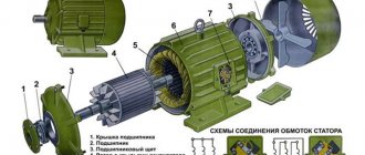
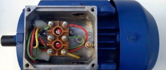
To convert an electric motor from 380 volts to 220, first open the motor cover to see how many ends there are on the stator windings. There can be 6 or 3 of them. If there are 6, then it is possible to change the connection diagram: if there was a “star”, you can switch to a “triangle”, and vice versa.
If there are only 3 ends, it means that inside the box the windings are already connected either by a “star” or a “triangle” (there are 6 ends in total, which are connected in pairs by terminals, there will be 3 of them, since there are 2 ends for each terminal). In this case, you will have to leave the previous scheme.
Attention! If you decide to change the connection diagram of the stator windings with three ends outside, you will have to open the motor housing with your own hands. It's labor intensive, but possible.
Winding connection
It doesn’t matter what the power source is, three-phase or single-phase, the stator windings can be connected in any of the following ways (you can read more about methods for connecting electric motors):
The windings are usually connected with a star if the motor will be powered from a 380 V network. Thanks to this, the start becomes smooth, although a third of the power is lost. The triangle is recommended when powered from 220 Volts. Inrush currents are not so high compared to those that arise from three-phase power. But the power is equal to that provided by a “star” connection if the motor is connected to 380 V.
See the diagrams below. The difference is that in the first case, all the beginnings are connected so that a three-pointed star is obtained. And in the second, the end of one winding is connected to the beginning of the next so that a figure with three vertices (a triangle) is formed.
Calculation of capacitors
When the ends of the windings are connected in a star or triangle, there are 3 places where they are joined. Terminals are placed at these places. When powered by 380 Volts, a phase is supplied to each of them. But our task, having the same 3 contacts, is to supply only 1 phase 220 Volts and zero. This can be done with your own hands, compensating for the lack of three-phase power supply with capacitors. The launcher will be active only for the duration of the launch, and the worker will be active permanently.
In order for an electric motor to start and operate well, you need to choose the right capacitor capacity. For a working drive it depends on the connection scheme. If it is a star, then the formula works:
If it is a triangle, then the formula changes its form:
Wed is the required capacity of the working storage element. U – network voltage (220 Volts). I is the current strength, which is found by the formula:
P – power, U – voltage already known to us, ƞ – efficiency, cosine “phi” – power factor. All these values can be found in the technical data sheet of your three-phase motor.
Calculating the capacitance of the starting capacitor (Cn) is simple: multiply Cp by 1.5 or 2. If Cp = 50 µF, then Cp will be from 75 to 100 µF. Alternately place one container, then another, starting the motor each time. Listen to the sound of the move: if there is no hum, then everything is in order.
Attention! Capacitors must be paper. For rebuilding an engine with your own hands, MBGP or MBGO work well. If you don’t find a drive of the required capacity, then connect several in parallel.
Assembly according to the diagram
The diagram above shows how to correctly connect the stator windings with capacitors and wires of a 220 V network with your own hands. You need to connect storage elements parallel to each other to one of the vertices of the triangle or star (provide a key to manually turn off the starting drive after overclocking). Then they are brought either to phase or to zero: it doesn’t matter. Only the direction of rotation of the shaft will depend on this.
Connection diagrams for "star" and "delta" in a three-phase network
It is more profitable to transmit electricity through high-voltage power lines, therefore, all residential areas and most industrial enterprises are powered through step-down transformers, the beginnings of the secondary windings, which are connected to each other, and the outgoing phase wires are connected to the ends of the windings.
The connection point of the coils is grounded and the neutral conductor is connected to it. This power supply scheme is called TN and is described in PUE Chapter 1.7.
There are two schemes for connecting electrical appliances to such a network, differing in the supplied voltage.
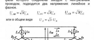
The most common connection scheme is “star”. Used when turning on electrical appliances whose supply voltage is 220V. In this case, one of the wires of each of the devices is connected to one of the phases, and the remaining ones are connected together and connected to the neutral.
In this case, the power of the devices may be different, which will cause the appearance of equalizing current in the neutral conductor, but the voltage on each of the electrical devices will be constant (with the exception of losses in the supply cables).
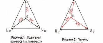
When three identical electrical appliances are connected in a star, there is no current in the neutral wire, so it is allowed not to be connected, but if one of the devices breaks down, the supply voltage of each of the remaining ones will be 190 Volts.
Therefore, a star without a neutral is used mainly when connecting a three-phase electric motor.
Less common is the “triangle” connection scheme. In this case, each of the electrical appliances is connected to two of the three linear conductors. The supply voltage for all electrical appliances will be 380V.
This scheme is used in electrical installations in which there is no possibility of connecting a neutral or grounding, for example, in mobile devices that are powered not by cables, but by current collecting plates.
How to connect in a star-delta connection (with three wires)
For the most part, domestically produced EDs already have a star circuit assembled. All that is required is to reassemble the triangle.
The main advantage of the star/delta connection is the fact that the engine produces maximum power.
Despite this, such a scheme is rarely used in production due to the complexity of implementation.
To connect the motor and make the circuit operational, three starters are required.
The current is connected to the first (K1), and the stator winding is connected to the other. The remaining ends are connected to starters K3 and K2.
Next, the winding of the last starter (K2) is combined with the remaining phases to create a delta circuit.
When the K3 starter is connected to the phase, the remaining ends are shortened and the circuit is converted into a “star”.
Please note that simultaneous activation of K2 and K3 is prohibited due to the risk of a short circuit or knocking out of the AV supplying the ED.
To avoid problems, a special interlock is provided, which means turning off one starter when turning on the other.
Pros and cons of three-phase and single-phase networks
Using a three-phase voltage of 380 V to power a private home has a number of differences from single-phase 220 V, so when deciding to connect to such a network, you should study all the advantages and disadvantages of such a power supply scheme.
A three-phase network has a number of advantages over a single-phase one:
- Smaller cross-section of suitable cable. With an even distribution of the load across phases, it is possible to increase the total power of electrical appliances.
- Connection of three-phase electric motors without additional devices and power loss. Conventional asynchronous electric motors, when connected to a single-phase network, lose a significant part of the torque or it is necessary to purchase a special converter.
- Additional opportunities for modernization and repair of electrical wiring. Knowing how 380 turns into 220, you can change the connection of electrical appliances depending on the specific situation.
In addition, in some cases, supplying three-phase power to the building allows you to obtain permission from the electric company to increase power consumption.
In addition to the advantages, the three-phase power supply circuit also has disadvantages:
- it is necessary to obtain permission to change the circuit from the electric company;
- additional costs for replacing the power cable;
- increased size and cost of equipment in the input panel.
General rules
Before switching on, be sure to check the voltage value for which the electric motor is designed - if you connect a potential difference greater than the specified one, the windings will overheat; if it is low, it will not start.
As a rule, on asynchronous machines two parameters are specified at once, less often only one:
The rating is determined together with the winding connection diagram - star or triangle. In the first case, the windings have a common point, and the phase wires are connected to the other three terminals of the coils. In the second, the end of one winding is connected to the beginning of the next in such a way that a closed circuit is formed. Some units are turned on only by a star, others by a triangle, and some can be independently connected in any of the ways; both characteristics are indicated on the nameplate of the electric motor.
For a triangle, the smaller voltage is used, and for a star, the larger of the two indicated. The difference is that three-phase motors connected in a star will have a soft start, while a delta motor can produce more power.
Physically connecting a three-phase electric motor to a single-phase network will not bring any result - the shaft will not rotate. The reason for this is the absence of an alternating electric field, which provides alternating effects on the rotor. Therefore, the problem can be solved by providing a bias in the electrical voltage and current in the phase windings. To get the desired result from one phase, you can additionally include a capacitor in the circuit, which will ensure a voltage lag of up to -90º.
However, it will not be possible to achieve a full voltage shift in the stator windings. Although the rated voltage is supplied to the electric motor, the efficiency will be only 30 - 50%, which will be determined by the connection diagram of the windings of the asynchronous electric motor.
Do not turn on the electric motor without load. Since it is not designed for such a mode, the electric machine will quickly fail. Minimize idling as much as possible.
Where to get 220 Volts if there are three phases in the shield
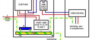
Most often, the question of how to make 220 volts from 380 is asked by residents of apartment buildings. In these buildings, in the entrance on each floor there is an electrical panel, which is connected to three phases, a neutral, and in some cases also grounding.
In such an electrical panel there are two voltages - linear 380V, between two different phases, and phase 220V, between any of the phases and the neutral.
In fact, to obtain single-phase voltage in a three-phase shield, it is necessary to connect a two-core cable to one of the phases and a neutral bus. If there is a grounding connection in the circuit, it is advisable to use not a two-core, but a three-core cable and connect it as follows, according to the rules for color marking of cables:
- brown vein - phase;
- blue or light blue - neutral;
- yellow-green - grounding.
| Important! To reduce the current in the cable suitable for the building, the connection of different apartments must be done evenly across all three phases. |
Scheme of how to make 220 volts from 380
There are several options for how to make 220 Volts from 380. The diagrams of such connections should be known to any experienced electrician:
- Connect a single-phase load to the phase and neutral wires. The neutral conductor usually has a smaller cross-section, or you can use a multimeter to look for them in a four-core cable. The voltage between phase wires will be 380V, and between phase and zero 220V.
- Use a 380/220 transformer. The power of this device must be equal to or greater than the power of the connected electrical appliance. The advantage of this scheme is that there is less risk of electric shock. Instead of a conventional transformer, you can use an autotransformer. This device has smaller dimensions, but does not protect against electric shock.
Where to connect the grounding
In addition to neutral and phase, modern electrical wiring uses another conductor - protective grounding. The housings of electrical appliances and lamps are attached to it.
If the insulation between these parts and live elements is broken, a short circuit occurs or a leakage current appears. As a result of this phenomenon, the circuit breaker or differential protection trips, respectively.
In a modern residential power supply system, three grounding schemes are used:
- TN-C. The old grounding system, in which the grounding of power lines is carried out only in the substation, on the neutral of the secondary winding of the transformer, after which a combined PEN conductor is supplied to the consumer, which simultaneously performs the functions of grounding and neutral. In this case, instead of protective grounding, there is a protective grounding and connecting electrical appliance housings to it is prohibited in PUE 1.7.132. To protect people from electric shock in such a system, it is necessary to use an RCD or a circuit breaker.
- TN-CS. This is a more modern system in which in the input panel the combined PEN wire is divided into neutral N and ground PE. The separation point is connected to the building's grounding loop. According to PUE clause 1.7.135, after separation, the connection of these conductors is prohibited. The grounding wire in the apartment electrical wiring in this system must be connected specifically to the PE conductor.
- TN-S. The most modern scheme in which power supply is carried out using five wires - three phase L1, L2 and L3, neutral N and grounding PE. In this case, the grounding is connected only to the grounding conductor.
As a last resort, it is allowed to connect the protective grounding to a separate circuit manufactured in accordance with the PUE standards, paragraphs 1.7.100-118. In this case, a CT grounding system will be obtained.
| Important! It is prohibited to use water, sewer or heating pipes as a grounding conductor. |

