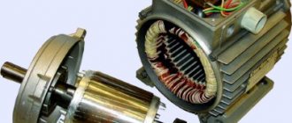
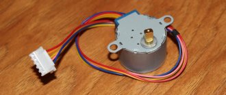
Connecting a single-phase motor
As a rule, our houses, garages and other outbuildings are connected to a 220V source, which is a single-phase network. In this regard, all consumers are designed to operate from a single-phase network made with two wires, one of which is neutral and the other phase. The operation of many electrical appliances involves single-phase electric motors, the connection of which involves some subtleties.
Connection diagrams for single-phase asynchronous motors
With starting winding
To connect a motor with a starting winding, you will need a button in which one of the contacts opens after switching on. These opening contacts will need to be connected to the starting winding. In stores there is such a button - this is PNDS. Its middle contact closes for the holding time, and the two outer ones remain in a closed state.
Appearance of the PNVS button and the state of the contacts after the “start” button is released"
First, using measurements, we determine which winding is working and which is starting. Typically the output from the motor has three or four wires.
Consider the option with three wires. In this case, the two windings are already combined, that is, one of the wires is common. We take a tester and measure the resistance between all three pairs. The working one has the lowest resistance, the average value is the starting winding, and the highest is the common output (the resistance of two windings connected in series is measured).
If there are four pins, they ring in pairs. Find two pairs. The one with less resistance is the working one, the one with more resistance is the starting one. After this, we connect one wire from the starting and working windings, and bring out the common wire. A total of three wires remain (as in the first option):
- one from the working winding is working;
- from the starting winding;
- general.
We work further with these three wires - we use them to connect a single-phase motor.
With all these
- Connecting a single-phase motor with a starting winding via the PNVS button
connecting a single-phase motor
We connect all three wires to the button. It also has three contacts. Be sure to place the starting wire on the middle contact (which closes only during the start), the other two - on the outermost (arbitrary). We connect a power cable (from 220 V) to the extreme input contacts of the PVNS, connect the middle contact with a jumper to the working one (note! not to the common one). That's the whole circuit for switching on a single-phase motor with a starting winding (bifilar) through a button.
Condenser
When connecting a single-phase capacitor motor, there are options: there are three connection diagrams and all with capacitors. Without them, the engine hums, but does not start (if you connect it according to the diagram described above).
Connection diagrams for a single-phase capacitor motor
The first circuit - with a capacitor in the power supply circuit of the starting winding - starts well, but during operation the power it produces is far from rated, but much lower. The connection circuit with a capacitor in the connection circuit of the working winding gives the opposite effect: not very good performance at start-up, but good performance. Accordingly, the first circuit is used in devices with heavy starting (concrete mixers, for example), and with a working condenser - if good performance characteristics are needed.
Circuit with two capacitors
There is a third option for connecting a single-phase motor (asynchronous) - install both capacitors. It turns out something between the options described above. This scheme is implemented most often. It is in the picture above in the middle or in the photo below in more detail. When organizing this circuit, you also need a PNVS type button, which will connect the capacitor only during the start time, until the motor “accelerates”. Then two windings will remain connected, with the auxiliary winding through a capacitor.
Functionality check
How to check engine performance by visual inspection?
The following are defects that indicate possible problems with the engine; they could be caused by improper operation or overload:
- Broken support or mounting gaps.
- in the middle of the engine has darkened (indicates overheating).
- through cracks in the housing.
To check the performance of the engine, you should first turn it on for 1 minute, and then let it run for about 15 minutes.
If after this the engine is hot, then:
- Perhaps the bearings are dirty, jammed, or simply worn out.
- The reason may be that the capacitor capacitance is too high.
Disconnect the capacitor and start the motor manually: if it stops heating, you need to reduce the capacitor capacitance.
AC brushed motor
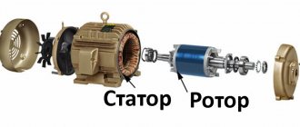
Consider a brushed AC motor. Universal commutator motors can be powered from both AC and DC sources. They are often used in power tools, sewing and washing machines, meat grinders - where reverse is needed, adjustment of the rotor speed or its rotation at a frequency of more than 3000 rpm.
The stator and rotor windings of a commutator motor are connected in series. Current is supplied to the rotor windings through brushes in contact with the commutator plates, to which the ends of the rotor windings are connected.
Reversing a single-phase motor with a commutator is carried out by changing the polarity of the stator or rotor windings being connected to the network, and the rotation speed can be adjusted by changing the amount of current in the windings.
The main disadvantages of such an engine:
- high price;
- the complexity of the device, the practical impossibility of repairing it independently;
- significant noise level, difficult to control, creating radio interference.
It remains to add that when using devices containing a single-phase electric motor, close attention should be paid to the choice of its type, connection diagram, and how to correctly calculate the elements.
Connecting a single-phase motor via a capacitor - 3 circuits
What happens with this?
If the heating is quite noticeable, then you need to look for its causes. If the capacity is significantly exceeded, intense heating will begin.
It is necessary that the rated voltage of the capacitor is equal to or greater than the calculated one. This is the optimal solution for achieving average performance. Afterwards it is turned off by a special device - a centrifugal switch or a start-up relay in refrigerators.
Secondly, and most importantly, the author was convinced in practice that even an extremely accurate calculation is not a guarantee of the correct operation of the engine. One of the windings is connected directly to the network, and the second is connected using a capacitor. In the geometric dimension, the windings in the stator are placed opposite each other. So, step by step, we figured out how to connect a three-phase asynchronous electric motor to a single-phase network and what you need to calculate and know for this.
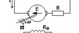
Operating principle and startup scheme
Principle of operation:
- An electric current generates a pulsating magnetic field on the motor stator. This field can be considered as 2 different fields that rotate in different directions and have equal amplitudes and frequencies.
- When the rotor is stationary , these fields lead to the appearance of moments of equal magnitude, but differently directed.
- If the engine does not have special starting mechanisms , then at start the resulting torque will be zero, which means the engine will not rotate.
- If the rotor is rotated in one direction , then the corresponding torque begins to prevail, which means that the motor shaft will continue to rotate in the given direction.
Launch scheme:
- The launch is carried out by a magnetic field , which rotates the moving part of the motor. It is created by 2 windings: main and additional. The latter is smaller in size and is a launcher. It is connected to the main electrical network through capacitance or inductance. The connection is made only during start-up. In low power motors, the starting phase is short-circuited.
- The engine is started by holding the start button for a few seconds, as a result of which the rotor accelerates.
- When the start button is released , the electric motor switches from two-phase mode to single-phase mode, and its operation is supported by the corresponding component of the alternating magnetic field.
- The starting phase is designed for short-term operation – usually up to 3 s. A longer time under load can lead to overheating, insulation fire and mechanism failure. Therefore, it is important to release the start button in a timely manner.
- In order to increase reliability, a centrifugal switch and a thermal relay are built into the housing of single-phase motors.
- The function of the centrifugal switch is to cut off the starting phase when the rotor reaches its rated speed. This happens automatically - without user intervention.
- The thermal relay turns off both phases of the winding if they heat up above the permissible level.
Option 3: changing the starting winding to the working winding, and vice versa
It is possible to organize the reverse of a single-phase 220V motor using the methods described above only if taps from both windings with all beginnings and ends come out of the housing: A, B, C and D. But there are often motors in which the manufacturer intentionally left them outside only 3 contacts. In this way, he protected the device from various “homemade products”. But still there is a way out.
The figure above shows a diagram of such a “problematic” motor. It only has three wires coming out of the housing. They are marked with brown, blue and purple colors. The green and red lines corresponding to the end B of the starting winding and the beginning C of the working winding are interconnected internally. We will not be able to access them without disassembling the engine. Therefore, it is not possible to change the rotor rotation using one of the first two options.
In this case, do this:
- Remove the capacitor from the initial terminal A;
- Connect it to the final terminal D;
- From wires A and D, as well as the phase, taps are made (you can reverse it using a key).
Look at the picture above. Now, if you connect the phase to tap D, the rotor rotates in one direction. If the phase wire is transferred to branch A, then the direction of rotation can be changed in the opposite direction. Reversing can be done by manually disconnecting and connecting the wires. Using a key will help make the job easier.
It's important to understand
Important! The last version of the reversible connection diagram for an asynchronous single-phase motor is incorrect. It can only be used if the following conditions are met:
- The length of the starting and working windings is the same;
- Their cross-sectional area corresponds to each other;
- These wires are made from the same material.
Reversing single-phase capacitor motor with remote control
Digital reverse circuit of a single-phase asynchronous motor on a PIC12F629 microcontroller
This simple digital device was developed to control a single-phase asynchronous electric motor type 6AE80 with a rated power of 1100 W. One of the conditions was the presence of a wired remote control with a cable 5-6 meters long, light weight of the remote control and low-voltage control (for the operator’s electrical safety). The device can be used with any single-phase asynchronous electric motor, but the power of the motor must be taken into account. For more powerful motors, it may be necessary to use electromagnetic relays in the circuit that can switch more current.
Electric motor 6AE80
Most often, electricians make such devices based on electromagnetic starters, which are almost powerful electromagnetic relays with 220-volt windings. For example, common contactors such as PML-1100. This is the most common solution, but for our purposes it has a number of disadvantages. The first is the large dimensions of the device on electromagnetic contactors, and the second is the need to pull large cross-section power wires to the control panel (push-button panel), through which a relatively large current flows and a dangerously high mains voltage of 220 volts is present. The picture below is a photo of one of these devices:
We see that such a device is comparable in size to the size of the electric motor itself.
I decided to develop a small-sized digitally controlled device using an inexpensive 8-pin PIC12F629 microcontroller.
The use of a microcontroller made it possible to control the motor with just two buttons (instead of the usual three buttons in reverse on starters). In this case, the operator does not need to think about stopping the engine before changing the direction of rotation - this is taken care of by the program “hardwired” into the microcontroller.
The photo shows my engine control panel. The remote control is connected to the controller unit with a soft, high-quality cable 6 meters long (If necessary, the cable length can be increased). A microphone cable with two cores and a screen is used. The cable has a diameter of 6 mm (in insulation). This cable is used in audio engineering to connect microphones. In principle, any three-core wire can be used. I used a microphone because it is of high quality, resistant to bending and breaks, and is designed for use in “extreme” conditions of live concerts.
Microphone cable (one option)
The control panel has two buttons. The green button is forward rotation, the red button is reverse, that is, rotation in the opposite direction (it should be noted that the directions of rotation are conditional).
If the engine is stopped, pressing any of the buttons starts the engine in the corresponding direction. If you press any of the buttons while the motor is rotating, the engine turns off.
On the body of the control panel there is a ring designed so that the remote control can be hung on the wall or on the operator’s neck (customer’s request). The motor is used with a gearbox in a pipe bending machine.
The housings of the control panel and the controller itself were designed in the SolidWorks 3D modeling program and printed on a 3D printer.
The body of the push-button panel (left) and controller (right), printed on a 3D printer.
Control controller mounted on the plastic cover of the junction box of the 6AE80 engine.
Changing the direction of rotation of a single-phase asynchronous motor
There are several types of asynchronous single-phase electric motors. This article is about capacitor start motors. such an electric motor has two windings - working (R.O.) and starting (P.O.). the working winding is connected directly to the 220 volt network, and the starting winding is connected through a special starting capacitor. The capacitor allows you to create a phase shift of the alternating current in the starting winding relative to the current in the working winding.
In this diagram (and in the distribution block of our 6AE80 engine), the beginning and end of the working winding are designated as U1 and U2, and the beginning and end of the starting winding are designated Z1 and Z2. In order to change the direction of rotation, it is enough to swap the beginning and end of any of the windings. Usually reverse is used along the working winding, but it makes absolutely no difference which winding beginning and end are changed. We will change the terminals of the working winding, that is, U1 and U2. So, the circuit for reverse switching will look like this:
It should be borne in mind that changing the direction of rotation of such an engine is possible only at the moment of its start. In this case, the engine armature must be stationary. If you switch the winding and apply power to the motor without waiting for its armature to stop rotating, the motor will start in the same direction in which it was rotating before, regardless of whether the winding is turned on.
Schematic diagram of the motor control controller
The printed circuit board is laid out in the DipTrace program, so the circuit diagram is also drawn in the DipTrace circuit editor. To enlarge the diagram, click on it with the mouse:
In this scheme, the PIC12F629 microcontroller is in charge. This is a small chip in an 8-pin package. The microcontroller is configured to operate from an internal (built-in) 4 MHz oscillator, so an additional quartz resonator is not needed here. Two microcontroller ports are used to control the motor. Port GP4 (pin 3) controls the electromagnetic relay (K1) for turning the engine power on and off. The direction of rotation is switched by a relay (K2) controlled by the GP5 port (pin 2) of the microcontroller. The microcontroller controls the relay windings through switches on relatively powerful transistors Q1 and Q2. These transistors are necessary because the output port of the microcontroller cannot provide enough current to turn on the electromagnetic relay. The electromagnetic relay coils are included in the collector circuits of transistors Q1 and Q2. Diodes, driven parallel to the relay coils with the cathode to the power positive and the anode to the transistor collector, protect the transistor transitions from inductive voltage surges that occur in the windings at the moment the relay operates.
To track clicks on the control buttons, microcontroller ports GP0 and GP1 (pins 7 and 6) are used. These pins are configured as inputs and are connected to the +5V power supply through resistors R5 and R6 with a resistance of 1 kOhm. The buttons themselves are not shown in the diagram, since the diagram was drawn for the layout of the printed circuit board, but there are no buttons on the printed circuit board; they are installed in the remote control. The buttons are connected to the board pins BTN_FWD (FORWARD button), BTN_REV (BACK button) and to the GND (ground) pin:
Remote control diagram
There are three LEDs installed on the controller body, which are not on the circuit or printed circuit board. The fact is that I decided to install LEDs already when I assembled the controller. The first, blue LED lights up when the power supply (+5V) of the controller is turned on. The second LED, red, lights up when the relay switching the direction of rotation (K2) is activated. The third LED, green, lights up when the engine is turned on, that is, 220V power is supplied to it.
If you want to install LEDs, their connection diagram is shown below. Also, if you wish, you can modify the controller circuit board; all files can be found at the end of this article. I was too lazy to modify the board, so I simply soldered three resistors using surface-mounted mounting and fixed the LEDs themselves in the holes on the controller body using a small amount of cyanoacrylate (superglue).
LED connection diagram
Controller power
As the power source for this controller, I used a regular pulse adapter for a smartphone with an output voltage of 5 V. For the controller to operate, it is enough that the adapter provides an output current in the region of 500 - 600 mA. My adapter turned out to be rated for 2 A. The only modification to the adapter was replacing the micro USB connector with a regular power plug, like this (male):
This connector is more reliable and practical than micro USB. I installed a mating part on the controller body - the “mother” socket
You can buy a ready-made 5 V adapter with such a plug. In our radio stores, such an adapter for a maximum current of 2 A costs approximately 200..250 rubles.
If you have a small mains transformer in your household with a voltage on the secondary winding in the region of 9 - 14V, you can assemble a power supply according to the classical scheme:
But I think that a purchased pulse adapter is a cheaper and, most importantly, “fast” option. You can also order such an adapter in China, on Aliexpress:
Printed circuit board
The printed circuit board is laid out in the DipTrace program. You can download the free version of the program for 400 pins. Its functionality is quite sufficient for such a board.
Below in the frame you can see a three-dimensional image of the printed circuit board. By clicking on the “play” button in the center of the image, you can “spin” the board in virtual 3D space and examine it in detail:
Induction Motor Controller by shantidas on Sketchfab
The large pads above the two orange relays are the high voltage part of the board. In the center of these round pins I drilled holes with a diameter of 3 mm, and using M3 fasteners (screw - nut - washer - washer - nut) I secured the wires from the electric motor and from the 220 volt network. Of course, you can just solder these wires if you are too lazy to bother with fasteners. When connecting the high-voltage part of the board, you must be careful and attentive to prevent short circuits in high-voltage circuits.
The printed circuit board is single-sided. There are three jumpers on it. One jumper is located on the low-voltage part of the board (to the right of resistors R4 and R2). It is made with a piece of mounting wire. The other two jumpers are located in the high voltage part of the board. To create them, you need to connect the points on the board with pieces of insulated wire with a cross-section of at least 1 mm: A1 to A2 (the first jumper) and B1 to B2. Be careful, the mains voltage operates at these points and the motor current flows through these wires. So don't use thin wire here
Connecting the electric motor to the board
Connecting the electric motor is not difficult, but I repeat, you need to be very careful here and check everything several times, since an error can cause a short circuit and “boom!!!”, since you are working with a 220V network voltage.
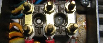
To successfully connect the electric motor, all 4 wires must be routed from its housing to the junction box, that is, the beginning-end of the working winding and the beginning-end of the starting winding. In some motors, the common connection point of the motor windings is located inside the housing and there is simply one common wire. It is impossible to connect such a motor in reverse. Our 6AE80 engine has all 4 ends removed from the housing and the installation was initially made on a three-pin mounting block inside the distribution compartment.
The blue and brown wires lead to the start capacitor. Let's leave them as they are.
the first thing to do is to disconnect the working winding wires from the circuit. In this motor they are marked U1 and U2. They need to be disconnected, extended with additional pieces of wire (cross-section 1.5 - 2 mm) and brought out through the “connection”, marked as U1 and U2. We connect two more pieces of the same wire to the block in the place where the ends of the working winding were screwed (in the photo these are the left and middle screws of the contact block) and also bring them out, marking them as KU1 and KU2 (Block-U1 and Block-U2). We connect these 4 wires to the contacts of the same name on the high-voltage part of the printed circuit board (behind the relay).
Connection diagram of the motor to the controller board
The thick lines show the wires that need to be added. Thin lines are what's inside the motor.
We connect the 220 volt network to contacts 220-1 and 220-2 on the controller board.
Controller Parts
U3 - microcontroller PIC12F629 Q1, Q2 - transistors BD139 K1, K2 - electromagnetic relay type RT424005 with a 5-volt winding and a switched current of 8 A.
D1, D2 - diodes 1N4001 All resistors with a power of 0.125 - 0.25 W with ratings indicated in the diagram. Capacitor C1 - ceramic at 0.1 uF Capacitor C2 - electrolytic at 47 uF 16V two normally open buttons for the remote control (I bought suitable ones in a radio store for 15 rubles)
Attention! To control larger motors, relays capable of switching higher current will be required. Such relays can be large in size and will have to be mounted separately.
Program for microcontroller
The firmware for the PIC12F629 microcontroller is written in C language in the MikroC Pro For Pic environment. To flash the microcontroller, you will need any of the programmers that can flash PIC microcontrollers.
in the archive: Program (firmware) for the microcontroller with source codes The firmware itself is the file Revers_12F629.hex. Also in the archive you will find a project for simulation in Proteus. This is the file Reves12F6298.pdsprj A printed circuit board project in DipTrace format and a 3D model for printing controller and push-button housings
A series of videos about the making of this device:
Reversing diagram of a three-phase motor in a single-phase network
Since a three-phase asynchronous motor will lack two phases, they need to be compensated with capacitors - starting and running, to which both windings are switched. The torsion of the shaft in one direction or another depends on where to attach the third.
The diagram below shows that winding number 3 is connected through a working capacitor to a three-position toggle switch, which is responsible for the forward/reverse engine operating modes. Its other two contacts are combined with windings 2 and 1.
When turning on the engine, you must adhere to the following algorithm of actions:
- Apply power to the circuit through a plug or switch.
- Move the toggle switch to switch operating modes to forward or reverse (reverse).
- Set the power switch to the ON position.
- Press the “Start” button for a time not exceeding three seconds to start the engine.
How to connect with reverse
There are situations in life when you need to change the direction of rotation of the motor. This is also possible for three-phase electric motors used in a household network with one phase and zero.
To solve the problem, it is necessary to connect one terminal of the capacitor to a separate winding without the possibility of breaking, and the second - with the possibility of transferring from the “zero” to the “phase” winding.
To implement the circuit, you can use a switch with two positions.
The wires from “zero” and “phase” are soldered to the outer terminals, and the wire from the capacitor is soldered to the central terminal.
Reversing single-phase synchronous machines
To start, these motors require a second winding on the stator, which includes a phase-shifting element, usually a paper capacitor. It is possible to reverse only those in which both stator windings are equivalent - in terms of wire diameter, number of turns, and also provided that one of them does not turn off after a set of revolutions.
The essence of the reversing circuit is that the phase-shifting capacitor will be connected to one of the windings, then to the other. For example, consider an AIR 80S2 asynchronous single-phase motor with a power of 2.2 kW.
There are six threaded terminals in its terminal box, designated by the letters W2 and W1, U1 and U2, V1 and V2. To ensure that the motor rotates clockwise, the commutation is performed as follows:
- Mains voltage is supplied to terminals W2 and V1.
- The ends of one winding are connected to terminals U1 and U2. To power it, they are connected by jumpers according to the scheme U1–W2 and U2–V1.
- The ends of the second winding are connected to terminals W2 and V2.
- The phase shifting capacitor is connected to terminals V1 and V2.
- Terminal W1 remains free.
To rotate counterclockwise, change the position of the jumpers; they are placed according to the scheme W2–U2 and U1–W1. The automatic reverse circuit is also built on two magnetic starters and three buttons - two normally open “Start” and one normally closed “Stop”.
Information
This site has been created for informational purposes only. The resource materials are for reference only.
When quoting site materials, an active hyperlink to l220.ru is required.
A document defining the rules of the device, regulating the principles of construction and requirements for both individual systems and their elements, units and communications of the power plant, conditions of placement and installation.
PTEEP
Requirements and responsibilities of consumers, responsibility for implementation, requirements for personnel operating the power plant, management, repair, modernization, commissioning of the power plant, personnel training.