A little about the excitation effect
The voltage generated by the generator at different engine speeds is regulated by the excitation windings. The current strength is maintained at a constant voltage within 13.8-14.2 V. To provide power to all vehicle systems, it is equipped with a voltage regulator (VR). The device is located inside the generator and is found both in the domestic automotive industry and on foreign-made cars. People call it a chocolate bar or a tablet.
The generator is connected to the battery by the positive terminal “30” (often called “plus”, “B” or “BAT”). A terminal with a negative potential is designated as “31” (the names “D” and “B-” are also found). The contact from the “chocolate box”, which is used to supply voltage from the car’s network after turning on the ignition, is designated as terminal “15” (“S”). Contact for supplying power to the charging indicator o (“D+”).
Stopping recharging the battery from the generator, in most cases, indicates failure of the “tablet”. But don’t be upset, because in this case you can apply voltage to the excitation windings and get to the nearest store or car service center. So, in order not to discharge the battery to zero, you will need to disconnect the “tablet” and then excite the generator.
What are SV and ARV
The gene excitation system is a complex of various devices, including: exciter, ARV, SGP, UBPV, de-excitation device, as well as additional test meters.
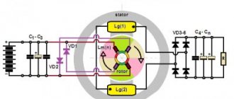
Excitation system
ARV is nothing more than a regulator that functions completely automatically. SGP is a means that dampens the magnetic field. UBVV is a device through which excitation is quickly boosted.
The exciter itself is the power source (PS) of the winding with constant voltage. In this case, the IP can be the gene itself, together with semiconductors and a rectifier unit (diode bridge).
ARVs are used in a synchronous gene. Here they perform the function of increasing the physical stability of the generating device. It is customary to classify ARVs into devices with proportional pitch and strong pitch. Some are capable of changing current energy due to a discrepancy in the stator voltage, while others react in a broader sense of the word.
When the current decreases, for example during a short circuit, a boost is provided. It implies a rapid increase in excitation, which affects the stop of voltage drops and maintains stability.
Correction and acceleration significantly increase the reliability of the relay.
When the generator shuts down, which can also be caused by internal short circuits, the unit should be energized. To do this, it is enough to extinguish the magnetic field, which will make it possible to reduce the size of damage to the stator winding.
To extinguish the magnetic field means to quickly reduce the magnetic flux of the gene excitation to a value close to 0. At the same time, the emf of the unit decreases.
Article on the topic: List of cars participating in the 2021 recycling program
How to extinguish a magnetic field
Magnetic field suppression is carried out using AGP - special automatic devices operating from a relay. They are the ones who help activate resistance.
In generating devices operating on the principle of thyristor excitation, the magnetic field is reduced by switching the main valves into an inverter mode. Thus, the energy saved in the winding will be transferred to the exciter or diode bridge.
It is characterized by a CB rated voltage (NT), but it can be different.
- 100 or 600 V, if we are talking about excitation at the winding terminals.
- 100 or 8000 A, if we are talking about LT located directly in the winding, and corresponds to normal, standard operation of the generator.
You should know that the LT of the exciter should be a fraction of a percent of the LT of the generator. As a rule, values of 0.2-0.6 percent of the nominal power of the gene are considered.
As for the speed of the exciter, it depends on the rate of increase in current strength on the inductor (rotor) winding.
The excitation system (excitation system) must be calculated depending on the operation of the automatic breaker. In other words, work without ARV is allowed, but only for the time needed for repair or replacement. In other cases, the use of ARV is mandatory.
Note. If the IV still operates without ARV, then it is necessary to provide an additional protection system. These are RDUs and other means that can provide deexcitation and auto-quenching of the generator field.
The SV is obliged to provide current in a continuous mode, exceeding the LT of the generator by at least 10 percent.
Non-contact excitation system
SV can also be semiconductor. In this case, it must have an internal storage mode (internal storage mode).
It is important that protective devices that ensure stability during overvoltages are multi-functional.
| Excitation system composition | What does the excitation system provide? |
| rectifier transformer | initial excitement |
| series booster transformer | idling |
| thyristor converter (TV 8-2000/) 050-1U4) | connection to the network using the method of precise synchronization in normal modes and self-synchronization in emergency modes |
| converter cooling system | operation of the main generator in the power system with loads from no-load to nominal and overloads |
| initial excitation unit (AN V-2) | underexcitation within the limits of stable generator operation |
| automatic excitation regulator (AU1G type ARV-SD) | excitation boost by current and voltage |
| field blanking panel | effective field damping |
| relay panels | deexcitation during normal unit stops |
Generator circuit
In order to be able to excite the generator at the right time, without using a battery, you should carefully study the diagram and operating principle of various modifications of the units. An important point is to understand why it is needed in general and exactly what functions it performs.
In simple terms, a generator is a device that serves to convert mechanical energy into electrical energy. It provides power to all electrical consumers in the car and recharges the battery while the engine is running. It is located in the front part of the engine, and operates via a crank shaft. On hybrids, the generator is used as a starter. However, such a scheme is sometimes found on cars with an internal combustion engine that have a stop-start system.
Based on this, we can conclude that generators come in two types, differing in design. Their main difference is how the rectifier unit, drive pulley and fan are located. In addition, generators with different circuits also differ in overall dimensions. The main parameters, regardless of the type, remain the same - they all have a rotor (inductor), stator, etc. in their design.
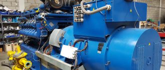
Below is a diagram of a domestically produced generator. It is found on almost all car models of our production.
And this is a more modern scheme, often found on VAZ from “eight” and above.
Now let's look at the generator connection diagram and how it works.
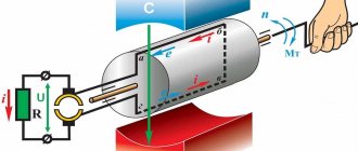
The main task performed by the generator rotor is to create a magnetic field. For these purposes, the shaft has an exciter winding (or VO). It is located on the protrusions of the “plus” halves. The shaft also has a contact group, which consists of two copper rims. Voltage passes through them to the excitation winding; for this they are soldered to the VO contacts.
Important! Sometimes there are rings made of other metals, such as brass or steel.
In addition, the fan impeller is also installed on the shaft. The drive pulley (VPD) is also attached there. Another important rotor component is the bearing.
Regarding the functions of the stator, it converts direct voltage into alternating voltage and consists of a metal core made up of plates and windings. The stator has 46 special slots into which the winding is placed. It allows you to accommodate three windings, so you can get a three-phase connection.
The rectifier unit is used to convert the current produced by the generator from alternating to direct for its subsequent supply to consumers. The block consists of six semiconductor diodes, two for each phase - plus and minus of the generator.
Brushes are needed to transfer the generated current to the exciter rings. They consist of a graphite element, brushes, springs for holding and pressing. On modern generators this unit is combined with the regulator into a single unit.
“Chocolate” is necessary to maintain generator currents at specified values. Today you can find electronic or hybrid regulators. In the hybrid design, the circuit contains radio components and electrical appliances. Electronic parts are made using TMT technologies.
The generator drive operates thanks to the rotation of a belt drive. This gives the same rotation speed to the inductor, which is required for its normal operation.
Hence, in most generator models, the excitation winding is connected by a separate group, which consists of two semiconductor diodes. The diode circuit is more often called a rectifier, and prevents current from flowing from the battery back through the circuit to the generator when the engine is stationary.
Worth knowing. When connecting the winding with a star circuit, two additional power diodes are installed on the zero terminal, this allows you to increase the generator power by 15%. The rectifier unit is installed on the generator using soldering or fixed mechanically.
The regulator is an extremely important part in the generator circuit; it is responsible for stabilizing the voltage when the crankshaft rotation speed changes. This process is completely automatic and occurs by acting on the excitation winding. That is, the regulator is responsible for the voltage frequency and pulse duration.
Interesting. The regulator changes the current supplied to the battery due to thermal voltage compensation. Simply put, the warmer it is, the less current flows to the battery.
Thyristor independent excitation systems (STN)
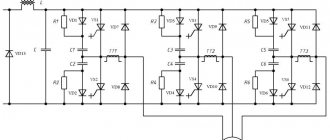
Independent thyristor systems (STN) are designed to power the excitation windings of large turbo and hydrogen generators with rectified controlled current, used in generating electricity at hydroelectric power stations and other generating stations - Fig. 5.2.
Abrahamyan Evgeniy Pavlovich
Associate Professor, Department of Electrical Engineering, St. Petersburg State Polytechnic University
Unlike self-excitation systems (SES), in STN the thyristor rectifiers of the main generator receive power from an independent power frequency AC voltage source - from an auxiliary synchronous generator rotating on the same shaft as the main generator
Fig.5.2. An independent thyristor system (STI) with an AC exciter and two groups of thyristors, in combination with a backup excitation circuit from a two-machine unit - an asynchronous motor-DC exciter. B – exciter (auxiliary generator) of alternating current, OVV excitation winding of the exciter, VRG, VFG – thyristor valves of the working and forcing groups, VVV – thyristor valves of the exciter rectifier, SUVRG, SUVFG, SUVVV – control systems for the valves of the corresponding groups, VTV – exciter rectifier transformer , TSNV – transformer MV of thyristor rectifiers.
The auxiliary excitation alternating current generator is built according to a self-excitation circuit. STN has an important advantage - its parameters do not depend on the processes occurring in the power system.
Vasiliev Dmitry Petrovich
Professor of Electrical Engineering, St. Petersburg State Polytechnic University
Thanks to the presence of an auxiliary generator, the excitation remains independent of the duration and distance of the short circuit and other disturbances in the power system, and the high rate of increase in the excitation voltage: no more than 25 ms until the maximum value is reached when the positive sequence voltage at the control point decreases by 5%.
The STN system ensures rapid de-excitation by changing the polarity of the excitation voltage: the de-excitation time from the maximum positive to the negative minimum excitation voltage does not exceed 100 ms.
Fig.5.3. Thyristor self-excitation system (STS) with a rectifier transformer (VT) and two groups of thyristors. TSNR, TSNF – transformers MV of thyristor rectifiers of working and forcing groups.
In the STN system, the rectified rated voltage can be 700 V, and the rectified rated current can be up to 5500A. The forcing multiplicity in voltage and current is at least two units, and the forcing duration is from 20 to 50 s. The accuracy of maintaining the generator voltage is no worse than ±0.5% and up to ±1%. The cooling system of the thyristor rectifier in the STN and STS systems can be forced air, natural air or water.
How to excite a generator
What is required to excite the generator? As mentioned earlier, the first step is to remove the “chocolate”, since the cause of the breakdown lies in it. Then the positive contacts on both devices are connected, and the negative ones in the regulator are cut and connected to the “ground” of the brushes.
Insulate the wire at terminal “30” of the generator. Connect an indicator of at least 15 watts to output circuit “15”. This applies to generators of the G222 series. On other models of units, excitation is carried out by connecting to terminal “B”.
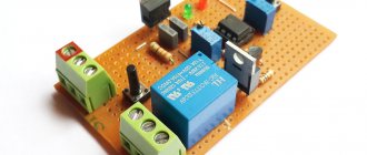
Generator self-excitation circuit.
The diagram shows diodes that are found only on modern types of generators; they are not present on earlier versions. It would be more correct to say that a circuit that does not have these diodes is classic, but one with them is newer.
Some generator models have armature brushes in their design. They also need to be removed and the tablet drilled out. One of the contacts is connected to the plus of the armature through a diode, the second - to the minus.
The current does not begin to flow immediately, but only after reaching a certain number of revolutions. Based on the tachometer readings, it can be determined that the feed will start only after 4 thousand revolutions per minute. That is, if we accelerate the engine to 4,000, the voltage appears, and if we reduce the speed to 1,000, the voltage will disappear. This is the principle of current generation during self-excitation.
Some car brands have a low-speed power plant. In this case, to increase the initial rotation speed, you will have to do something to the pulley. There shouldn't be any problems with regular engines.
Let's look further. It is important to know that at the output of the generator we will not receive 12 V. In the absence of a regulator (tablet), the unit will produce everything it can, depending on the speed, at times even up to 30 V. For example, at start this figure jumps to 36 V. You can see this by connecting the lamp to the appropriate voltage at the generator output. And then it gradually drops to 20 volts.
Of course, the scheme can be improved. For example, by adding a capacitor to the positive wire going to the armature. This is necessary so that when the engine speed decreases, the voltage does not drop. A high-quality capacitor will also be useful at the output; this will smooth out the first voltage surge and regulate subsequent dips.
When assembling such a circuit, it is worth remembering about the output of high voltage. It is significantly higher than the normal 12 V, so there is a danger of burning out the light bulb, ECU and other electronics of the car.
Remember! When operating from self-excitation, the generator will transmit all the released electricity that it can generate, and this can cause severe overheating of the unit itself. A slight overload and you can go for a new unit. Accordingly, it is recommended to use this method only in cases of extreme necessity.
Brushless diode systems (BDS)
Brushless diode systems (BBD) are designed to power the excitation winding of turbogenerators with rectified controlled current - Fig. 5.4a, b. The brushless exciter is a synchronous generator of reverse design, the armature of which with an alternating current winding and a diode rectifier is rigidly connected to the rotor of the excited turbogenerator. The excitation winding of the exciter is located on its stator.
The main advantage of brushless exciters is the absence of slip rings and brush contact in the turbine generator rotor winding circuit and the reduction in machine length.
Abrahamyan Evgeniy Pavlovich
Associate Professor, Department of Electrical Engineering, St. Petersburg State Polytechnic University
This makes it possible to provide excitation of heavy-duty machines, the excitation currents of which exceed 5500A, characteristic of the STN system - Fig. 5.2. The rectified rated voltage is up to 600V, and the rectified rated current is up to 7800A. The cooling system of the rotating diode rectifier is natural air.
Regulation of the generator excitation is carried out by controlling the current of the excitation winding of the reversed exciter. A typical system set includes an automatic field suppression device, a thyristor arrester and two conversion-regulating channels (AVR-1, AVR-2) of automatic excitation regulators of the main and reserve channels, respectively. One of the channels (AVR-1) is in active mode, the other (AVR-2) is in hot standby. In a particular case, the main control channel receives power from a rectifier transformer connected to the generator busbar, and the backup channel receives power through a rectifier transformer from the power plant’s auxiliary busbars.
Fig.5.5. Brushless diode system (BBD) with thyristor excitation (TV-1, TV-2) of the exciter winding (OVW). SG – synchronous generator; OVG – generator excitation winding; DSV – diode synchronous exciter; DV – rotating diode rectifier; B – inverted synchronous exciter and its excitation winding OVV; TV-1, TV-2 – thyristor rectifiers of the first and second channels for powering the air supply; VT-1, VT-2 – rectifier transformers of the first and second channels; ARV-1, ARV-2 – automatic excitation regulators of the first and second channels; P1, P2, P3, P4 – disconnectors; TT1, TT2, TN1, TN2 – measuring current and voltage transformers of the first and second channels; TA11, TA12 – exciter excitation current sensors; AGP – automatic field extinguishing device; TR – thyristor discharger.
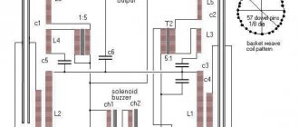
Fig.5.6. Brushless diode (BBD) excitation system for a diesel generator. SG – synchronous diesel generator; OVG – excitation winding; DV – diode rectifier; T – thyristor; ARV – automatic excitation regulator; ITT, ITN – current and voltage measuring transformers; TST with MSh is a three-winding summing transformer with a magnetic shunt.
The brushless diode excitation system (BDS) has a lower operating speed compared to thyristor systems (STS and STN). Thus, the time for the rise of the excitation voltage to the maximum value when the positive sequence voltage at the control point decreases by 5% of the nominal value is no more than 50 ms, whereas in thyristor systems it is no more than 25 ms.
In the circuit in Fig. 5.4a, the excitation winding of the diode exciter is powered from a magnetoelectric subexciter with permanent magnets, and in the circuit in Fig. 5.4b - from a rectifier transformer connected to the generator current lead of the excited machine. In both cases, a thyristor rectifier controlled by the ARC system is used to power the excitation winding (OVW) of the reversed exciter (B).
Fig.5.7. Brushless diode (BBD) excitation system for a diesel generator. SG – synchronous generator; OVG – generator excitation winding; DSV – diode synchronous exciter; DV – rotating diode rectifier; B – reversed synchronous exciter; OVV – exciter excitation winding; PV – magnetoelectric subexciter with permanent magnets; ARV – automatic excitation regulator; TV – thyristor rectifier for power supply of OVV.
As one of the modern variants of the circuit in Fig. 5.4b with a rectifier transformer (VT), Fig. 5.5 shows a brushless diode system (BDS) with thyristor power supply via two channels (from the MV network through VT-2 and from the generator conductor through VT-1) exciter excitation windings (ECW).
Basic generator malfunctions
Let's look at the most common malfunctions typical of a car generator:
- Electrical circuit breaks, short circuits and other damage. To diagnose such a defect, it is necessary to check the current strength and voltage indicator at the output contacts of the unit. Based on the information received, a decision is made on further actions.
- Motorists also often encounter problems such as excessively worn graphite brushes, a voltage regulator, or a diode bridge. Any worn or failed part should be replaced with a new one. As for the regulator, as mentioned above, it ensures optimal recharging of the car battery based on the temperature in the engine compartment. In other words, the device automatically determines the required voltage for the battery under given conditions. Some generator models feature manual switching of modes depending on the time of year. In this case, low temperatures will not have a negative effect on the operation of the device. The failure of the relay will be signaled by voltage drops in the system - this could be a weak light from the headlights while driving, which light up brighter as the engine speed increases.
- Faulty bearings. If this element breaks down, extraneous increased noise will appear, although the same symptom is also observed if the unit is poorly lubricated.
- Noises and howls. If such signs are detected, it is necessary to check the separator elements, raceways, and slip rings for rotation. Such symptoms may also indicate the possible occurrence of an interturn short circuit in the winding of the stator element or traction relay. In any case, if extraneous noise is detected during operation of the generator, it is recommended to conduct a thorough diagnosis of the condition of the contacts.
- The operating temperature of the generator can sometimes reach 90 C, however, in case of obvious overheating, it is necessary to immediately check the functionality of the diode bridge. In addition, you should determine whether the vehicle’s on-board network is overloaded with additional devices and third-party devices. In the event of a critical increase in temperature, the first thing that will happen is that the insulation of the stator winding will darken; in the worst case, it may even melt.
- Severe wear on the alternator belt. If excessive wear occurs, the unit belt may simply break, which leads to its overall malfunction. That is, in this case, all consumers will consume electricity from the car’s battery. If the belt breaks, the generator stops performing its functions, which means the driver has very little time to get to the nearest car service center or service station. Such a defect can be indicated by voltage drops in the on-board network of the machine. In this case, you should check the belt for integrity, carefully inspect its surface for cracks, tears, delaminations and other mechanical damage. If they are found, it is recommended to replace it immediately.
If any defect is discovered, it is better to immediately fix it yourself or contact a car service. Otherwise, you risk facing more expensive repairs.
How to test a generator using a light bulb and a multimeter
Checking the functionality of the generator is possible in several ways; for this you will need to use certain methods - this could be measuring the output current of the generator, the voltage drop on the wires connecting the current output of the generator to the battery, or checking the regulated voltage.
For diagnostics, you will need a multimeter, a battery and a light bulb with wires soldered to its contacts, wires to connect the generator to the battery, and you can also take a drill with a specific head - it may be needed to rotate the rotor through the pulley nut.
The connection diagram is as follows: output terminal “B+” and rotor D+. The lamp fits between the generator output and the D+ contact. Then the power wires connect the negative on the battery to the generator ground. “Plus” from the battery, respectively, with the plus of the generator and the B+ terminal. The structure is securely fixed in a vice and connected.
The multimeter is switched to DC voltage measurement mode, one probe is connected to the “plus” of the battery, and the second to the “minus”. If everything is in order, the lamp will light up, and the voltage should be 12.4 volts.
Then, use a drill to spin the generator. At this moment, the lamp should go out and the voltage should rise to 14.9 V. Then a load is added - for this purpose you can use an H4 halogen lamp. It is also hung on the battery terminals, after which it should light up.
Next, the generator is turned again with a drill. The voltmeter should record a voltage of 13.9 volts. Without a drill, the battery should produce approximately 12.2 volts. If this does not happen or the readings are very different, then the generator is faulty.