Connection procedure and specifics
Connection diagram
Although the limit microswitch itself is designed quite simply, it can be used in technological equipment rich in electronics. It follows from this that it should be connected by an experienced specialist who is well versed in switching circuits of electronic components.
A typical example of such a connection is the installation of a mechanical switch in a typical 3D printer, during the operation of which it is necessary to fix the extreme position of the carriage. The mounted switch has 3 contacts with the following designations: COM, NO, NC. In the open state, the first and third terminals have a voltage of +5 Volts (while the second contact is reliably grounded). When the movable carriage reaches its extreme position, a connection appears between COM and NC, after which it locks and rebounds by approximately 2 mm.
Such a sensor is connected via two conductors in red and black insulation. When installing another type of switch (with an indicator), a more complex circuit is used, in which another conductor is provided - in green insulation. When the push-type microswitches in the printers are triggered, the LED lights up and a characteristic click is heard. Its connector, located on the switching board, has special designations:
- the red wire is marked as V (+5 Volts) and is used to connect the corresponding voltage;
- the black conductor is connected to point G (or ground);
- The green bus is set to S (signal).
The same signs are also present on the optical limit switch connector, which more accurately fixes the position of the carriage.
It works completely silently, reaching the extreme position is accompanied by LED indication. Its disadvantages include the possibility of failures due to heavy dust or exposure to direct sunlight.
Connection rules
Despite the fairly simple design of limit switches, they are used in electrical equipment where there are complex electrical circuits. As a result, they must be connected by specialists who know how to work with circuit diagrams for connecting limit switches. The sensor is connected with two wires, red and black. The first is under voltage, the second is without it. They are installed in the circuit as indicated in the diagram.
When the device is triggered, a click is created. The indicator type of switch is connected in the same way as a regular mechanical one. There is also a third green wire. The LED will indicate that the switch has tripped with a click.
Note! Operation failure may occur due to dust and sunlight. If the optical pair works, the light-emitting diode turns on.
Limit switch - device design and principle of operation
A limit switch is used to control and limit the movement of various mechanisms.
It must have the following characteristics: reliability of operation, safety for people and devices, high mean time between failures.
There are a large number of varieties of these switches: mechanical, magnetic, inductive. Each group is divided into subgroups. It all depends on where this or that device will be used.
Purpose of limit switch
Switching of 220V AC electrical circuits can be carried out using limit switches.
The action of the devices and their operation is determined by the contact contact of the end parts of the moving elements of the pneumatic drive, consisting of two-position pipeline fittings.
In addition, they can be used as limit switches that act as a position sensor in other devices, in systems used in industrial automation.
Design and operation of the switch KV-1, KV-2
The operating principle of the KV-1 (single-position, two-channel), KV-2 (two-position, single-channel) linear movement devices - limit switches is to use a permanent magnet printed circuit board with two reed switches, they are used as the main elements that switch the electrical circuit.
In addition to the board in the “limit switch” housing, the limit switch device contains a terminal block; in the main (first) housing there are two blind holes in which the rod goes; for KV-02 there are 2 rods. A permanent magnet, a magnetic circuit and a return spring are attached to the rod.
The action of the rod is reciprocating, with its help the magnet moves and closes and opens the contacts.
Rice. No. 1. Photo of the limit switch KV-01, KV-02.
Rice. No. 3. Drawing of the KV-1 limit switch indicating the overall and installation dimensions of the KV-01 and the location in the cable entry structure.
Limit switch KV-04
The design of the KV-04 (two-position, single-channel, rotary) is in principle similar to previous devices. Unlike a single-position switch, it is complicated by the presence of a rotary lever, with which you can adjust the angle of rotation of the axis clockwise and counterclockwise. Thus, the reed switches are switched.
Rice. No. 4. Drawing with dimensions of switch KV-04
The adjustment occurs by changing the cams located on the washer; they act on the levers, when turned, the magnet moves, switching the reed switch.
Fig. No. 5. Schematic electrical diagram for connecting the KV-04 limit switch.
Rice. No. 6. Photo limit switch KV-04.
Non-contact limit switches
Limit or, as they are also called, travel switches are non-contact, they operate based on the use of electromagnetic relays, as well as on the use of logical elements, the operation occurs without influence from the moving part of the device.
Non-contact limit switches are divided into two main types according to the principle of operation and the effect on the sensitive element:
- Mechanical impact.
- Parametric influence, due to changes in the physical parameters of the converter.
Parametric switches are divided into the following types:
- Inductive.
- Capacitive.
- Optical.
The connection of such devices is based on the use of a 2- and 3-wire circuit. In the case of a 3-wire circuit, power comes through a special wire.
Rice. No. 7. Contactless limit switches (sensors).
Non-contact limit switches are subject to increased requirements for operational reliability, because such devices have to operate under difficult conditions.
The location of these devices is in the working area of machines and assemblies, where they may be exposed to significant high temperatures, may be subject to shock and operate under the influence of strong vibration.
They can also be under the influence of a strong magnetic field, they can be affected by various, including aggressive liquids and contaminants.
Particularly important is the high requirement for increased switching frequencies, especially when used in complex technologies, for example, machine lines operating in automatic mode, complex transport systems, metallurgy and foundries.
Reasons for a false Starline signal
So, your signaling has encountered a glitch. The locks are definitely closed, but the light indication on the display stubbornly blinks. Why does the Starline alarm show an open door on the key fob? The options are listed below.
Problem with limit switches or wiring
Check the contact connections, connectors, wires, limit switches.
- Perhaps the wire responsible for closing the central lock is broken, which is why Starline A9 shows the door open. Damaged cables and connection points must be replaced. It is advisable to seek help from an experienced auto electrician.
- The limit switch is a small device connected to the main alarm unit via a wire. It physically unlocks/locks the central lock, having received the corresponding “electrical” command. The end switch could be damaged, for example, water got into it, or it could move or move away from the body. If necessary, the device is easy to change. It’s easy to check, just press lightly, thereby simulating pressing (that is, closing the door). Now arm the car and study the key fob display. If it still shows an open lock, the problem is not with the limit switch.
Eliminate the possibility of incorrectly connecting wires. The indication that the door is open will light up on the Starline key fob only if you carried out repairs or diagnostics literally the day before.
Breakage in the key fob
You could drop it, get it wet, or subject it to other mechanical stress. You must have a spare remote control. We recommend trying to arm your car using it. If as a result the system does not indicate the door is open, replace the first key fob or disassemble and repair.
Another key fob for the Starline E90 alarm sometimes shows that the car is open if its battery runs out. “Living out his last days,” so to speak. Replace the power supply and check that the device is working properly.
The software settings in the key fob have gone missing
The instructions for the security system provide a step-by-step algorithm for re-flashing
Please note that if you have several key fobs in your hands, you should re-register them all, and in one cycle
Problem with the main control unit
Perhaps your security system was initially installed incorrectly, or at some point there was a software failure. You should contact the installers. If you suspect a manufacturing defect and the alarm is still under warranty, visit the official Starline service center.
Glitch after replacing car battery
Often the Starline A93 alarm shows an open door instead of a closed one after replacing the battery. You set the car to security, but the doors do not lock. This is exactly what the light indication of open doors on Starline A91 shows. Try registering the remotes again. And if you can’t reprogram the key fob, you’ll have to go to a service station.
That's all for us. Now you know why the “open door” icon sometimes blinks by mistake on the Starline A39 remote control. The situation is not pleasant, but easily solvable. Especially if you contact installers. Well, if your hands grow out of place, you can handle it yourself. Good luck!
Kinds
There are one-, two- and three-pole devices. The first two are designed for a load of 10-25 A, the permissible voltage is 220V. Three-pole devices can withstand a voltage of 380 V, while the load is slightly reduced, it should not be more than 15 A.
Open, closed and completely sealed bags are available. Open type switches do not have a protective shell. These packagers are used to switch connections at a safe voltage and only indoors. Closed devices are equipped with a housing made of plastic or metal. The terminals of these devices are protected from touch, and the device itself is perfectly protected from dirt and dust. Closed models can be installed outside the panel cabinet.
Sealed electrical appliances are enclosed in a non-flammable, shockproof, hermetically sealed plastic shell. The high level of protection allows the devices to be installed in open spaces. Some models are equipped with a transparent window through which you can monitor the status of the contacts.
The popularity of packaged devices is gradually declining, but the production of such electrical appliances has not ceased. Reliability, availability, and speed of operation help baggers still remain a sought-after product.
How to connect a limit switch
Before connecting the wires of devices, it is necessary to turn off the electricity by making a switch in the panel. Limit switch installation requires careful adjustment of the response.
To install and connect the device, you need to fix the door using four self-tapping screws so that when closed it presses on the limit switch key, and when open the button is released. Connect the electrical circuits of the switch through the terminal block to a current of 220 V.
The limit switch in the electrical circuit should be the last element before the supply wire.
For the front door
The limit switch on the front door is designed to ensure the functioning of the alarm system and activate the light in the apartment. It is more advisable to install contactless sensors, since they take up little space and are quite reliable in operation.
Before installation, the position of the door and the limit switch should be taken into account. To connect the electrical circuit device, it must be done on a fireproof base for fire protection purposes. Installation and adjustment of the switch should be done with a certified tool.
For wardrobe
The purpose of installing limit switches is to provide automatic lighting when the door is opened. First you need to lay electrical wiring to the cabinet. At the ends of sliding doors, it is required to install a door mechanical switch with a voltage of 220 volts. All wires must be laid in protected trays. Then the installation of the lamp and end strips are marked. After installation, the wires are connected and the operation of the limit switches is adjusted.
For sliding doors
For sliding doors, the installation of a limit switch is similar to that for furniture, but an ultrasonic sensor should be used.
For swing doors
For swing doors you need to use a mechanical push-button switch type 4313WD. Wires to the installation site are laid in trays. Setting up the operation of the switch with your own hands must be done carefully without damaging it, since the working stroke of the rod is 3.5 mm.
For gates
Roller mechanical limit switches are used to automatically open and close gates. Installation is possible only on sliding gates, since they have less play in the mechanical part than swing gates. At the ends of the gate it is necessary to install end gates, which will be connected to the opening drive motor and to the starter.
When installing switch devices on gates, the conductors are supplied to the electric motor in a corrugated pipe, and the switch is installed in a moisture-resistant housing.
For auto
The installation of limit switches in the car is necessary for the functioning of the alarm and lighting. A simple push-button switch is used on the hood and trunk doors. For interior doors - contactless. After connecting the limit switches for the car, you should adjust the sensitivity of the security system.
Loading …
Operating principle
There are many types of limit switches. This list includes mainly mechanical and electromagnetic devices.
Mechanical switches
Mechanical limit switches are common in everyday life and in production. They are push-button, lever or with rollers.
Mechanical limit switches: a – push-button; b – lever; c – roller
Inside the case there are electrical contacts, the diagram of which is depicted on the outside. They can be opening or closing. A single limit switch is rare. Typically, at least a pair of contacts are used - normally open and closed. This universal design makes it possible to select the required switching scheme.
One of the types of limit switches are microswitches. The principle of their operation is the same, but the working element has a small stroke. Due to this, careful setup is required during installation. The operating stroke of the microswitch can be increased by using an intermediate link, for example, a lever with a roller.
The door limit switch is triggered when it hits the wheel and moves it along with the rod down.
Diagram showing the operating principle of a limit switch
The rod opens the upper contacts and de-energizes the connected device, or turns on something with the lower contacts, such as lighting or an alarm system.
The device should be checked to ensure that there are no misconfigurations.
Magnetic devices
The limit switch operates reliably - a reed switch that closes or opens contacts when a magnet is brought to it (Fig. a). The non-contact operating principle increases the reliability of the device. Reed switches are widely used due to their low cost and compactness (Fig. b). They are often used instead of mechanical limit switches.
Reed switch sensor: a – principle of operation; b – appearance
The reed switch is used in conjunction with a permanent magnet. They are placed separately in plastic cases, mounted respectively on the fixed and moving parts. The reed switch is then connected to the circuit being monitored. When the door is closed, the magnet is in connection with the reed switch and closes its contacts. As soon as the door begins to open, their connection is broken and the contacts open. The device operates with a small current and is connected to an open circuit.
Depending on the purpose, reed switches with normally open, closed or switching contacts are selected.
Inductive devices
Switches are used for elevators, lifts, metal doors and gates. When a metal object appears near the sensor, the inductive reactance of the choke winding increases sharply, which leads to a decrease in the current in the winding of relay K1 and its shutdown. In this case, its contacts K1.1 in the power circuit open.
Unlike reed switches, the devices react to metal and do not require a magnet. They are made from large sizes to microswitches. Fastening is done with nuts, bolts, glue and other methods.
Induction limit switch: a – operating principle; b – appearance (type VBI-M12); FM – object having ferromagnetic mass; L1 – throttle; K1 – electromagnetic relay
To prevent large currents from passing through the microswitches, you need to install an intermediate relay in the circuit for connecting lamps. The advantage of their use is thin wiring to the switches, since small currents flow through them.
As a relay, you can use the MRP-1 model, mounted on a DIN rail. A simple RP-21 relay or a 55 series microrelay will do.
Cheap car limit switches can be used as “micrics”, for which you need to create a convenient mount with your own hands.
An interesting option for turning on the light in the closet is a motion sensor, which is triggered when the door is opened and supplies voltage to the lamp.
Magnetic devices
Reed switches
Limit switches that respond to a magnetic field are assembled on the basis of a reed switch. A reed switch is a device that contains a pair, or more, of contacts made of a special ferromagnetic alloy.
When a magnet is brought near, they close (or open). The advantage of this design is the absence of mechanical contact, which significantly increases the service life of such a limit switch.
To install it, it is important not to forget about the magnet, since there will be no reaction to ordinary iron. The scope of application of this model is very wide. Essentially, this is a microswitch that can be discreetly placed anywhere
For example, it can be connected to a car alarm to discourage those who like to drain gasoline
Essentially, it's a microswitch that can be discreetly placed anywhere. For example, it can be connected to a car alarm to discourage those who like to drain gasoline.
The operating principle is simple. When the door is closed, the magnetic field acts on the microswitch. The circuit is closed, everything is fine. When you open the gas tank cap, the magnet comes off, the contact breaks and the alarm goes off.
Inductive models
As a rule, these are also not separate devices, but blocks: one housing can contain several pairs of contacts. The sensors have different designs: fastening with bolts, nuts, or glue. The sizes are also very different: from large to microswitches. Such limit switches require supply voltage. They are used as motion limiters for various mechanisms.
A limit switch of this type replaced mechanical models quite a long time ago. It is more convenient because it does not require direct touching. In addition, having an inductance coil in its design, such a limit switch reacts to metal, which means there is no need to install a separate magnet.
As you can see, limit switches have a fairly wide range of models. For the most part, these are blocks containing contacts in various designs, which makes the limit switches more versatile. Large, strong housings are required for work under heavy mechanical loads. Microswitches are widely used both at home and in industry. Everyone can find the right model for themselves.
Types and Applications
The end cap can be protective or functional. The first is used to activate downward movement, and the second is used to regularly turn lights or similar objects on and off. Both varieties are actively used in construction, mechanical engineering, metallurgy and industrial automation.
It is also worth pointing out that it can be roller, lever, float and push-button. There are microswitches, the scope of which is electronics and household appliances.
Scope of equipment application
Mechanical
Mechanical or contact conductors are those that operate at the moment of direct action on a pin with a button, wheel or lever. Provides a control signal with a warning. A serious disadvantage of each of these varieties is burning with contact sticking during repeated switching on and off.
You may be interested in this Three-zone counter
The mechanical type is push-button, roller and lever. It is used in production and metallurgical workshops, machinery and construction. Equipped with a rubber seal and make/break contacts.
The mechanical variety is one of the most common
Push-button
Push-button conductors are used to turn on lights or other electrical devices by pressing a button. The impact can be either by pressing a button or by pressing an extended rod. Installing them takes a short time.
Roller
Switches are electromechanical devices designed to control objects. Widely distributed in industrial and domestic spheres. Such devices operate not due to an electric pulse, but due to mechanical action on the roller. At the moment of effort, the contact closes or opens, and a control or signaling type signal is sent. Similar products are used in metallurgy, construction and mechanical engineering.
Note! Most often, they are equipped with making and breaking contacts and rubber seals.
Roller variety as a simply plug-in model
Lever
Limit switches operating due to an actuator or door. They have a similar operating principle as push-button models. The main difference is the presence of a lever connected to the moving part of the contacts. It is worth pointing out that float and slider models work in a similar way.
Contactless
Limit switches that are triggered when an object approaches in a certain area. Created as opposed to the mechanical type and refers to perfect models. They operate thanks to transistor switches with low resistance. Non-contact models are capacitive, inductive, optical and ultrasonic.
Contactless modern model
Capacitive
End switches that interact with people. At the moment a person approaches, an electrical capacitance is created, thanks to which the multivibrator operates. The closer the person, the greater the capacitance and the lower the pulse frequency. This element has great sensitivity.
Note! The main function lies on the plate tightly attached to the capacitor part.
Inductive
Electronic proximity switches that respond to the moment the magnet moves. Depending on the equipment of the metal or non-magnetic core in the sensor, electrical impulses are generated, thanks to which the key is closed or opened.
The inductive model as one of the classic
Optical
Limit switches equipped with an infrared LED and a special transistor that pick up the signal. The phototransistor works no matter what the lighting is. When the LED beam is interrupted, the photocell closes. This turns off the actuator where it is connected.
You might be interested in: Features of a circuit breaker
Limit switches equipped with an infrared LED and a special transistor that detect the phototransistor.
Ultrasonic
Limit switches equipped with quartz sound emitting elements. Volumetric motion sensors are also used. The amplitude of the sound changes when quartz sound elements appear within the operating radius.
Easy to work with ultrasonic model
Magnetic
Conductors that are activated when a certain spatial point approaches. They are tuned to a magnet, which is part of the design of the moving mechanism. They have one or more ferromagnetic contacts. When the magnet approaches, the contacts close, and a signal about this is sent to the control circuit. The main advantage of such a device is the complete absence of mechanical action and a noticeable increase in service life. Each magnetic limit switch is created in a glass or plastic housing.
Note! It has miniature dimensions.
Automotive
Limit switches used in signaling with lighting. They belong to the mechanical model, since they have the same operating principle. By design, they have one output with a connected positive potential and a negative terminal - a housing that is clamped to a metal body. In this case, it is necessary that the limit switches be protected from paint.
Spindle
Limit switches limiting the movement mechanism, used as a limit switch. Can be used where there is shaft rotation. Thanks to the rotating mechanisms, the contact group of the input limiter, rotating shaft or cyclic control limit switch is switched.
Spindle model as the easiest to work
Pneumatic
Conductors that respond to system pressure, which stops the supply of air with any gas. Devices that stop compressed air or other gas by pressing a control button or lever. At the same time, there are varieties that are triggered when a specific system pressure is reached.
Limit switch markings
Microswitches and microswitches, regardless of their characteristics, have specific markings. After decoding it, it is possible to obtain all the information about each limit switch model. If an entry like “VU222M” is found on it, this indicates a switch of the corresponding series. As an example, let’s decipher the labeling of a widely used product brand VP 15M4221-54U2. It means that its design has one moving element of the 15 series, as well as one make and break contact.
Limit switch markings
All switching elements in this series are controlled by a pusher with a roller built into the housing.
The degree of protection on the drive side of the structure corresponds to IP54, and the “U” symbol means climatic version. The following number 2 is the category of placement of the product, which corresponds to TU U 31.2-25019584-005.
Design features of a limit switch with a roller
A design of this type is one of the options for implementing a push-button type, only with a modified button. Installing a roller can significantly expand the functionality of the device. If the button can be pressed only in the axial direction, then the roller will respond to any impact - axial or tangential, the main thing is that the vector of this impact is in the plane of rotation.
Limit switch device
The spring-loaded rod on which the roller is mounted is a movable element on which two pairs of contacts are installed - normally closed and normally open. When pressed, one pair opens and the other closes. This design is usually called the plunger type KV.
Limit switch type plunger-roller
It is used primarily on lifting mechanisms and devices with vertical movement of moving parts. For horizontal elements it is used to a limited extent, only when the accuracy of the impact and limited effort are guaranteed.
There are lever roller designs. The roller is mounted on a rotary lever, which, when turning, closes the contact group inside the housing. This design is convenient in mechanisms where it is impossible to precisely adjust the force and range of contact with a moving element due to high inertia, vibration, and uneven movement.
Lever limit switch
The risk of destruction of such a device due to too sharp or intense contact is much less than when using a plunger-type limit switch. They are usually installed on massive and large moving elements with increased inertia - elevators, escalators, trolleys, mine elevators, sliding gates of hangars, etc. Sometimes such structures are called limit switches, since they have the ability to be triggered by moving elements passing without stopping.
There are KV models with adjustable lever length. They allow the length of the roller support to be changed, which expands the capabilities and scope of the device.
Roller limit switch with adjustable lever
There are also designs where a lever is added as an additional element to increase safety. If you unscrew it, the HF takes on the appearance of a regular push-button device. Most microswitches have this design.
Microswitches
End switches - what lies behind this name
When a car door or hood is opened, an alarm is installed, small parts are replaced, everyone always remembers the limit switches. For owners of Niva, Logan, Chevrolet, Lanos, Logan, Kalina or others, they look different. The limit switches may look like ordinary switches, which are located on the door, trunk and other necessary points, or they may be hidden inside the door - this type of arrangement is used for Kalina cars, because there the limit switches are located in the door locks. This arrangement is less convenient than the external one, but is also more reliable. Limit switches are small systems that act as switches and are practically impossible to do without.
Impulse relays
Controlling lighting using pulse relays is a completely different approach than those described above. Pulse relays are often used where it is necessary to control light from two or more places (to infinity), not limited by the load of the lines and the area of the premises. The main difference is that control by this method occurs using push-button switches (buttons) and a pulse relay mounted on a DIN rail in the electrical panel. There are also relays that can be installed in junction boxes, socket boxes or lamps, but these are used much less frequently.
The operating principle of a pulse (bistable) relay is quite simple. When voltage is applied to the relay coil (by pressing one of the control buttons), a pulse occurs, which closes the contact and opens after a second pulse. This is achieved by the fact that in such relays the armature has two stable positions, which change with each new short-term power supply to the coil and remain motionless after there are no contacts (i.e. the relay does not require constant power to hold the contacts).
As you can see in the diagram, to connect the relay you need to run two cables to the electrical panel where the relay will be installed. A cable from a group of buttons and a cable from a group of lamps, which makes it easy to change in the future to any other method of lighting control when needed.
In the future, new lighting schemes will definitely be added, following new technologies and trends.
blog comments powered by DISQUS back to top
Areas of application
Each type of limit switch is typically used in various fields of activity. By application they can be divided into:
- Protective, which are installed to protect the mechanism or personnel from ill-considered actions. For example, a cage lowering people into a mine will not begin to move until all its doors are closed, thereby ensuring the safety of the miners.
- Functional. They regularly turn lights or other electrical mechanisms on or off. The most obvious example of such a device, known to everyone, is the turning on of the light in the refrigerator when the door is opened.
In general, the use of limit switches depends on the possibility of the mechanism for its use and the imagination of the designer. People don’t even realize how often they have to deal with this electrical mechanism:
- in everyday life and household appliances;
- in the automobile and in the automotive industry;
- in furniture products;
- in production to solve a wide variety of problems.
Types of sensors
So, what exactly is a sensor? A sensor is a device that produces a specific signal when a specific event occurs. In other words, the sensor is activated under a certain condition, and an analog (proportional to the input effect) or discrete (binary, digital, i.e. two possible levels) signal appears at its output.
There are a great variety of sensors. I will list only those types of sensors that electricians and electronics engineers have to deal with.
Inductive. Activated by the presence of metal in the trigger zone. Other names are proximity sensor, position sensor, inductive, presence sensor, inductive switch, proximity sensor or switch. The meaning is the same, and there is no need to confuse it. In English they write “proximity sensor”. In fact, this is a metal sensor.
Optical. Other names are photosensor, photoelectric sensor, optical switch. These are also used in everyday life, they are called “light sensors”
Capacitive. Triggers the presence of almost any object or substance in the field of activity.
Pressure. There is no air or oil pressure - a signal to the controller or the emergency circuit breaks. This is if discrete. There may be a sensor with a current output, the current of which is proportional to absolute or differential pressure.
Limit switches (electrical sensor). This is a simple passive switch that trips when an object runs over or presses against it.
That's enough for now, let's move on to the topic of the article.
Areas of use
Application of a limit switch in a lifting mechanism
Known types of limit switches are in demand in a wide variety of human activities. According to their functional orientation, they are divided into the following types:
- protective action limit switches;
- devices for individual use.
The first ones are installed to protect mechanisms and people from actions not provided for by the operating rules of the devices. For example, elevator mechanisms do not move until their door curtains are completely closed. Their main purpose is to ensure human safety when using various mechanisms.
Devices for individual use are used in household appliances or industrial units where it is necessary to record a certain moment of movement. When closing the doors of the refrigerator, the lighting in it is turned off by a contact switch, and when opened it turns on again.
When installing a limit switch in a swing door control chain, for example, it is fixed with self-tapping screws inside a cabinet built into the wall. When closed, the door body presses the control button, opening the electrical circuit for lighting the interior spaces. When it opens, the push-button contact is restored and closes the working circuit, after which the light comes on.
Magnetic limit switches
Gecko switch
A special place is occupied by sensitive devices that are triggered by a magnetic field. These products, otherwise called reed switches, replace mechanical switch models. Their ferromagnetic contacts, placed in a glass flask, close or open when a permanent magnet is placed nearby. Due to its simplified design, the dimensions of this device are very small, making it easy to install in a break in the controlled circuit.
The contacts in it can be normally closed, as well as normally open or switchable, and the choice of a specific type depends on the nature of the movement, including the reverse mode.
When installing magnetic reed switches, be sure to take into account their polarity. If the poles are confused, they will not work.
Magnetic limit switches are widely used in the design of sliding gates. Some models are part of the security alarm control unit mounted at the entrance to the house. Often these devices are installed in modern furniture to control interior lighting, for example. The built-in furniture light switch is the most convincing example of their effectiveness. The absence of mechanical contacts in this design is its indisputable advantage, which helps to extend the service life of the product.
Design features of a limit switch with a roller
A design of this type is one of the options for implementing a push-button type, only with a modified button. Installing a roller can significantly expand the functionality of the device. If the button can be pressed only in the axial direction, then the roller will respond to any impact - axial or tangential, the main thing is that the vector of this impact is in the plane of rotation.
Limit switch device
The spring-loaded rod on which the roller is mounted is a movable element on which two pairs of contacts are installed - normally closed and normally open. When pressed, one pair opens and the other closes. This design is usually called the plunger type KV.
Limit switch type plunger-roller
It is used primarily on lifting mechanisms and devices with vertical movement of moving parts. For horizontal elements it is used to a limited extent, only when the accuracy of the impact and limited effort are guaranteed.
There are lever roller designs. The roller is mounted on a rotary lever, which, when turning, closes the contact group inside the housing. This design is convenient in mechanisms where it is impossible to precisely adjust the force and range of contact with a moving element due to high inertia, vibration, and uneven movement.
Lever limit switch
The risk of destruction of such a device due to too sharp or intense contact is much less than when using a plunger-type limit switch. They are usually installed on massive and large moving elements with increased inertia - elevators, escalators, trolleys, mine elevators, sliding gates of hangars, etc. Sometimes such structures are called limit switches, since they have the ability to be triggered by moving elements passing without stopping.
There are KV models with adjustable lever length. They allow the length of the roller support to be changed, which expands the capabilities and scope of the device.
Roller limit switch with adjustable lever
There are also designs where a lever is added as an additional element to increase safety. If you unscrew it, the HF takes on the appearance of a regular push-button device. Most microswitches have this design.
Microswitches
Installation and connection - step-by-step instructions
Connecting mechanical type limit switches is not difficult and is no different from the installation method of a standard device. A phase break connection is made to contacts of the required type (normally closed or open). The difficulty lies in the installation and adjustment of the HF, which requires correct location on the supporting structure.
It is necessary to install the device body so that the roller is in contact with a given element of the moving part, but does not protrude too far forward, risking breaking. If the moving structure is large in size and weight, it can vibrate during movement, which must be taken into account when adjusting the position of the roller.
For such structures, it is more correct to use switch models with an adjustable lever to adjust the position of the roller in place. Let's consider the procedure for installing HF on sliding gates. To work you will need:
- Welding machine.
- Screwdriver, set of wrenches.
- Pliers.
- Bulgarian.
- Roulette, ruler.
- Point probe for identifying phase wires.
Step-by-step instruction:
Step 1. Mark the extreme positions of the leaf when the gate is closed and open. Weld metal platforms on the supports (guides) for installing the HF. At the same time, it is recommended to secure the metal pipe into which the wire will be placed.
We install a place for limit switches
Step 2. Place the sash in its extreme position and mark the centers of the holes for the bolts on the support platform. Perform the same steps on the second site. Drill holes and secure switches.
We fasten the mechanism itself
Step 3. Unscrew the caps and connect the wires, previously tightened into the pipe with wire. Connect the wires to the control panel and check operation. Adjust the position of the switches and, if necessary, install additional stops to ensure reliable interaction of the rollers with the moving sashes.
Connect and check functionality
Advice! The final adjustment of the roller position is made by changing the length of the lever. It is recommended to avoid extreme positions in which the roller could be torn off. The optimal option is from the maximum to the first third of the lever length.
Video - Connecting limit switches
ECM device
The ECM is a cylinder-shaped device very similar to a conventional pressure gauge. But unlike it, the ECM includes two arrows that set the setpoint values: Pmax and Pmin (their movement is carried out manually along the dial scale). A moving arrow showing the real value of the measured pressure switches contact groups that close or open when it reaches the set value. All arrows are located on the same axis, but the places in which they are fixed are isolated and do not touch each other.
The axis of the indicator needle is isolated from the parts of the device, its body and scale. She rotates independently of others.
The bearings with which the arrows are attached are connected to special current-carrying plates (lamellas) connected to the corresponding arrow, and on the other side these plates are brought out into the contact group.
In addition to the above components, the ECM, like any pressure gauge, also has a sensitive element. In almost all models, this element is a Bourdon tube, which moves along with a pointer rigidly fixed to it; also, a multi-turn spring is used as this element for sensors that measure medium pressure more than 6 MPa.
For example, consider connecting the electric drive of the GZ-A valve
This electric drive is multi-turn, powered by three-phase alternating current. GZ-A contains remote alarm control circuits, which for clarity we will not consider in the example.
The operation of the circuit will be controlled by an electrical contact pressure gauge of the DM type. As switching elements, we will use PAE magnetic starters of the third magnitude with four contacts operating for closing and two for opening; we use only one of the breaking contacts (Fig. 2).
Rice. 2
Let us assume that at the initial moment the valve is in the closed position. When the pressure of a liquid or gas decreases, the pressure gauge closes the wire of phase C through the min contact, and the normally closed contact KPZ3 to the armature of the PO starter, and along the circuit from the neutral wire - through the limit switch of the “open” position KVO and the clutch switch MBO. The PO magnetic starter bypasses the DM pressure gauge circuit by closing the KPO2 contact. To prevent the valve closing trigger circuit from being triggered, the software blocks the PZ starter, breaking the power circuit with the KPO3 breaking contacts. When the valve is fully opened, the KVO contact opens and the circuit is de-energized.
When the maximum pressure is reached, the max output of the DM pressure gauge closes. The PZ closing starter is connected to phase C on one side through the pressure gauge contacts and the normally closed contact KPO3, and on the other - through the closing contacts of the limit switch KV3 and the coupling switch MVZ - to the neutral wire. The PZ closes the power circuit of its armature with the contacts of KPZ2, providing a full cycle of closing the valve. Contacts P3 turn on the electric drive in reverse, the reverse connection of phase wires A and C compared to the PO contacts. When the valve is completely closed, the PZ circuit is de-energized by the KVZ limit switch.
Clutch switches are designed to protect the motor at high shaft torque. Re-closure of the contacts of the MVO and MVZ occurs during reverse rotation of the engine.
The DM type electric contact pressure gauge is capable of switching up to 0.5 A, which ensures direct connection of PAE starters, the armatures of which consume a maximum of 0.25 A when turned on at a voltage of 127 V. The maximum load switched by the contact group of the starter is 17 kW, and to turn on the electric drive there is enough power of 0.18 kW. In practice, it is recommended to turn on the magnetic starter control circuits through intermediate relays (Fig. 3) to prevent burning of the pressure gauge contacts.
Rice. 3
When using intermediate relays, the number of involved contacts of the magnetic starter (software and freezing) is reduced to three. Each intermediate contact is controlled by two contacts that operate to close (to bypass the power circuit of the electrical contact pressure gauge and turn on the contactor armature) and one to open (to prevent the operation of the motor reverse circuit). Otherwise, the diagram is similar to that shown in Fig. 3.
Trunk limit switch
Standardly, a limit switch is installed in the trunk to activate the backlight in it; on cars with a standard alarm system, it also serves to control opening during active security. The limit switch can also be used by the standard central locking, blocking locking if the trunk is not slammed shut.
If we are talking about a cheap car with a minimum configuration, then you will have to connect the trunk limit switch yourself when installing the alarm. It’s easiest for owners of those cars where more expensive equipment includes a standard trunk alarm switch: as with doors, here it is enough to install the original part in the designated place. Otherwise, alas, you will have to drill a hole and install a universal one. Increasingly, the switch is not installed as a separate part in the trunk, but is built into the lock itself, as is the case with the doors.
Sometimes this leads to serious problems: for example, on the Renault Koleos, a failure of the trunk locking mechanism has become a “trademark disease”, and in the author’s practice, the “anti-record” is only a week after purchasing a new car. The lock, not locking, did not allow the built-in limit switch to operate, and this, as on other cars on similar platforms, blocked the locking of the central locking as a whole; due to the non-locking trunk, the owner could not lock the doors. In such cases, it was necessary to tightly block the trunk lock in a locked state until a new one arrived for a warranty replacement.
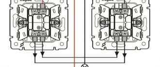
Connection diagram for a pass-through switch with 2 places
The circuit of a pass-through switch from two places is carried out using two pass-through single-key devices that work only in pairs. Each of them has one contact at the entry point, and a pair at the exit point.
Before connecting the pass-through switch, the connection diagram clearly displays all the stages; you should de-energize the room using the appropriate switch located in the control panel. After which it is necessary to additionally check that there is no voltage in all wires of the switch. To do this, use a special screwdriver.
To complete the work you will need: flat-head, Phillips and indicator screwdrivers, a knife, side cutters, a level, a tape measure and a hammer drill. To install switches and lay wires in the walls of the room, appropriate holes and grooves must be made in accordance with the device layout plan.
Unlike conventional switches, pass-through switches have not two, but three contacts and can switch the “phase” from the first contact to the second or third
Hood switch
What is a hood switch? This is still the same rod switch, except that the rod is longer than in the doors or trunk. Since the hood end is located on the front frame, the distance to the hood is quite large, which is why it is necessary to use a long rod.
This is the most rarely installed standard limit switch. On cars without a standard alarm system, it can be used by the factory only for the engine compartment lamp, which is offhand only remembered from the VAZ “eighth” family. Therefore, these alarm switches have to be connected independently, and therefore at least one limit switch is always included in the security systems.
But it also happens the other way around: for example, on Renault Megane 3 and Fluence for the Russian market it is standard in all trim levels except the minimum one, and is even built into the hood latch. And there are even wires going to it... but it’s impossible to find them in the cabin, because they remain under the hood, not connected anywhere. When installing an alarm, of course, you don’t have to install your limit switch, but you still have to run the wires under the hood.
This alarm switch will be the most problematic: water and dirt will get under the edge of the hood, causing corrosion, or failure of the switch, or false alarms. Therefore, you need to carefully select the location, if possible installing the limit switch in the cleanest available location.
Leading manufacturers in the segment
Many companies produce such sensors. Among them there are recognized leaders. Among them is the German company Sick, as the main manufacturer of such high quality products. Autonics supplies the market with contactless limit switches of inductive and capacitive types.
High quality contactless sensors are produced by the Russian company. They are characterized by ultra-high tightness (IP 68). These limit switches operate in the most hazardous environments, including explosive ones, and various installation methods are available.
Ukrainian limit switches are popular. Switches and limit switches VP, PP, VU are produced here. The warranty, subject to compliance with all operating rules, is 3 years.
Operating principle of contactless sensors
The operating principle of contactless switches (sensors) is based on changing the amplitude of oscillations of the generator when a specific material of a certain size is introduced into the sensitive zone of the sensor. The switching distance of the device is set depending on the needs of the process and the type of sensor. The non-contact method of recognizing the object of influence can significantly increase the reliability of the device due to the absence of moving and rubbing parts.
The list of functional capabilities of contactless sensors is wide. Detecting the position of an object, counting, positioning and sorting objects on conveyors, monitoring movement and speed, detecting breakdowns of mechanisms, determining the angle of rotation, measuring skew and many other functions are included in the concept of a “proximity sensor,” as a contactless switch is also called.
That is why they are used in a wide variety of industries: from metalworking to food production, as an element of transport automation and for control in machine tool industry, for managing water and gas, oil supply and on offshore oil refining platforms. To select a suitable switch, it is worth familiarizing yourself with the classification of sensors according to the principle of their operation.
Inductive proximity switches
Inductive sensors respond to metallic, magnetic, ferromagnetic or amorphous materials of the desired size. The effect is achieved by changing the amplitude of the generator oscillations when an object enters the sensitive zone of the sensor.
Select an inductive switch:
by parameters by analogues by industry by labeling
Capacitive proximity switches
Capacitive switches detect both metallic and dielectric objects. The operating principle of the switch is based on changing the capacitance of the capacitor, which acts as a sensitive element, when objects are introduced into the sensitive zone.
Select a capacitive switch:
by parameters by analogues by industry by labeling
Optical proximity switches
Optical proximity sensors detect monitored objects that reflect or interrupt optical radiation. The switching element for optical contactless sensors is semiconductor or relay. The range of these sensors can reach 150 meters.
Select an optical switch:
by parameters by analogues by industry by labeling
Magnetic sensitive proximity switches
Magnetic-sensitive sensors are used to detect a magnetized object in space. The sensor is triggered when the magnetic field strength changes, caused, for example, by the movement of a permanent magnet located on the moving part of the mechanism.
Select a magnetically sensitive switch:
by parameters by analogues by industry by labeling
Non-contact sensors can be manufactured in particularly robust housings made of special materials, in accordance with the NAMUR standard, as well as with acceptance 5.
Advantages of contactless sensors (switches):
- operating frequency: up to 3 kHz, Hall effect up to 15 kHz;
- high reliability;
- unambiguous dependence of the output value on the input value;
- stability of characteristics over time;
- small size and weight;
- no back impact on the object;
- increased tightness IP 68
- various installation options
- work under various operating conditions: in general industrial conditions
- in wide temperature ranges (from -60C° to +150C°)
- at high pressure (up to 500 Atm)
- in aggressive environments
- in hazardous areas
Advantages of contactless models
The main advantage of contactless switches is energy savings. Electricity is not wasted when there are no people in the room. The person does not need to be involved to turn the light on or off. Therefore, the use of such models is considered comfortable.
Technical simplicity is an advantage of standard contact switches, but there are some disadvantages:
- Small resource when applying maximum load. If the contacts open, a spark occurs, causing the switch to break. In the presence of direct current, a capacitor connected in parallel to the contacts will help eliminate the accident. If AC networks are present, you will need a refractory tungsten solder.
- The downside of the contact device is considered to be strong sensitivity to dust and dirt. This causes a disruption in the electrical circuit. Next, there is a decrease in the interaction of contacts, and as a result, overheating and breakdown.
A huge selection makes it possible to find an element to use in a particular case. If you need to implement touch control, a capacitive switch is suitable, but for use in dirty conditions it is better to choose an inductive option.
How to find limit switches quickly and without any problems
Many people do not quite know where the limit switches are located in Kalina, Niva or other cars. But when you have to install an alarm, searching for them takes quite a lot of time. In order not to waste extra time on inspecting the interior of your own car, you should use the following tips:
These methods will help the car enthusiast find absolutely all limit switches if he needs to connect an alarm system or replace these switches with new devices. The limit switches are designed to make it easier for the driver to deal with different systems of the car, and it doesn’t matter whether it’s a domestic car - Niva, Kalina or foreign models, everything will be as comfortable as possible.
Limit switches are very small in size, are installed in many places on the car, and perform specific functions. These devices are designed for comfortable access to a functional range of certain vehicle systems and simplify the process of connecting an alarm system. Each limit switch is responsible for the operation of its zone, but they can be connected to the same wire. Connecting to different wires is no less common. Negative and positive limit switches are found in both foreign and domestic cars - the interiors of Niva, Viburnum and the external space of the car. They are easy to buy, you can replace them yourself, and every motorist can connect additional wires to them independently.
Source