Radio electronics for beginners
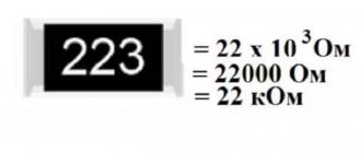
The housing dimensions of flat SMD resistors are standardized and divided into standard sizes. The standard size of the chip resistor is indicated in the form of four (less often five) digits, which are the size code. Typically, it records the length and width of the resistor in inches.
In fact, there are two systems for encoding the sizes of SMD components (including resistors). One of them uses the length and width of the component in inches , and the other uses millimeters .
For example, inch size 0805 is the same as 2012 in the metric system. In fact, the metric system is more convenient because measurements are rounded off in inches. For the same size 0805 (0.08″ x 0.
05″) length in millimeters is 2.0 mm and width 1.2 mm. If we convert the length and width into inches, we get 0.0787″ (2.0 mm) and 0.0472″ (1.2 mm).
These values are rounded to 0.08″ and 0.05″ (size 0805).
- It just so happens that the most common is the first, inch SMD case size coding system, although it is outdated.
- Below is table No. 1 with size codes for SMD resistor housings.
- Since there are two coding systems, the table shows size codes in both the inch ( inch or imperial ) and metric ( metric ) coding systems.
- For example, 0805 = 0.08(length) x 0.05(length) (in inches).
- In the other - metric, in millimeters.
For example, 2012 = 2.0 (length) x 1.2 (width) (in millimeters). Same size as 0805 in inches.
In order not to confuse one system with another, in technical documentation for the metric system the letter M is often indicated after the numeric code (for example, 2012 M ).
Table No. 1. Code designation of the standard size and the corresponding length and width of the element.
| In inches | L, length, length (inches) | W, width, width (inches) | Metric | L, length in mm. | W, width in mm. |
| 0050 | 0,008 | 0,004 | 0201M | 0,2 | 0,1 |
| 0075 | 0,012 | 0,006 | 03015M | 0,3 | 0,15 |
| 01005 | 0,016 | 0,008 | 0402M | 0,4 | 0,2 |
| 0201 (02016) | 0,02 | 0,01 | 0603M | 0,6 | 0,3 |
| 0202 | 0,02 | 0,02 | 0605M | 0,6 | 0,5 |
| 0204 | 0,02 | 0,04 | 0510M | 0,5 | 1,0 |
| 0303 | 0,03 | 0,03 | 0808M | 0,8 | 0,8 |
| 0306 | 0,03 | 0,06 | 0816M | 0,8 | 1,6 |
| 0402 | 0,04 | 0,02 | 1005M | 1,0 | 0,5 |
| 0404 | 0,04 | 0,04 | 1010M | 1,0 | 1,0 |
| 0406 | 0,04 | 0,06 | 1016M | 1,0 | 1,6 |
| 0408 | 0,04 | 0,08 | 1020M | 1.0 | 2,0 |
| 0502 | 0,05 | 0,02 | 1406M | 1,4 | 0,6 |
| 0504 | 0,05 | 0,04 | 1210M | 1,2 | 1,0 |
| 0505 | 0,05 | 0,05 | – | 1,2 | 1,2 |
| 0508 | 0,05 | 0,08 | 1220M | 1,2 | 2,0 |
| 0510 | 0,05 | 0,1 | – | 1,2 | 2,5 |
| 0603 | 0,06 | 0,03 | 1608M | 1,6 | 0,8 |
| 0606 | 0,06 | 0,06 | 1616M | 1,6 | 1,6 |
| 0612 | 0,06 | 0,12 | 1632M | 1,6 | 3,2 |
| 0616 | 0,06 | 0,16 | 1640M | 1,6 | 4,0 |
| 0805 | 0,08 | 0,05 | 2012M | 2,0 | 1,25 |
| 0808 | 0,08 | 0,08 | 2020M | 2,0 | 2,0 |
| 0815 | 0,08 | 0,15 | 2037M | 2,0 | 3,7 |
| 0830 | 0,08 | 0,30 | 2075M | 2,0 | 7,5 |
| 1005 | 0,1 | 0,05 | 2512M | 2,5 | 1,2 |
| 1008 | 0,1 | 0,08 | 2520M | 2,5 | 2,0 |
| 1010 | 0,1 | 0,1 | 2525M | 2,5 | 2,5 |
| 1020 | 0,1 | 0,2 | 2550M | 2,5 | 5,0 |
| 1206 | 0,12 | 0,06 | 3216M | 3,2 | 1,6 |
| 1210 | 0,12 | 0,1 | 3225M | 3,2 | 2,5 |
| 1218 | 0,12 | 0,18 | 3245M (3248M) | 3,2 | 4,5-4,8 |
| 1224 | 0,12 | 0,24 | 3250M | 3,2 | 5,0 |
| 1225 | 0,12 | 0,25 | 3264M | 3.2 | 6,4 |
| 1505 | 0,15 | 0,05 | 3812M | 3,8 | 1,2 |
| 1806 | 0,18 | 0,06 | 4516M | 4.5 | 1,6 |
| 1808 | 0,18 | 0,08 | 4520M | 4,5 | 2,0 |
| 1812 | 0,18 | 0,12 | 4532M | 4,5 | 3,2 |
| 1825 | 0,18 | 0,25 | 4564M | 4,5 | 6,4 |
| 2007 | 0,2 | 0,07 | 5320M | 5,3 | 2,0 |
| 2010 | 0,2 | 0,1 | 5025M | 5,0 | 2,5 |
| 2220 | 0,22 | 0,2 | 5750M (5650M) | 5,7-5,6 | 5,0 |
| 2225 | 0,22 | 0,25 | 5664M | 5,6 | 6,4 |
| 2512 | 0,25 | 0,12 | 6432M (6332M) | 6,4-6,3 | 3,2 |
| 3014 | 0,30 | 0,14 | 7836M | 7,8 | 3,6 |
| 3921 | 0,39 | 0,21 | 1052M | 10,0 | 5,2 |
| 4527 | 0,45 | 0,27 | 11070M (11470M) | 11,0-11,4 | 7,0 |
| 5931 | 0,59 | 0,31 | 1577M | 15,0 | 7,75 |
| 6927 | 0,69 | 0,27 | 17570M | 17,5 | 7,0 |
Table No. 1 presents size codes that are also used for ceramic SMD capacitors (2220, 2225, 1825, 0505, 0204, etc.), SMD resistor assemblies, and SMD LEDs.
This was done because surface mount technology is rapidly developing, and those sizes that were previously used only in the production of ceramic capacitors or SMD LEDs can also be used in the production of chip resistors or their assemblies.
In the technical documentation for resistors, you may also come across standard sizes such as 0804, 1506, 2009, etc. You should not be surprised by this. As a rule, these are standard sizes of assemblies.
Since the thickness of the element is not included in the size coding, it is necessary to refer to the documentation of the manufacturer of this component. Typically, the thickness of ceramic chip capacitors (MLCC) is greater than the thickness of chip resistors of the same size.
I note that not all size codes are shown in the table, since in fact there are very, very many of them. Naturally, there are also popular ones, for example, such as 0603, 0805, 1206, which are not only in demand by electronics manufacturers, but are also well known to radio amateurs.
Sometimes in practice it is necessary to determine the size of an SMD resistor. How to do it?
You can determine the size of an SMD resistor by measuring its length and width with a millimeter ruler. Naturally, you are unlikely to be able to accurately measure the dimensions of tiny chip resistors unless armed with a magnifying glass or microscope.
Next, we find the metric standard size in the table, which corresponds to the obtained values of the length and width of your resistor. We compare it with the code in inches.
At the time of writing, the smallest size was 0050 (inch). It is already present in the technical documentation, but this does not mean that chip elements of this standard size are actively used in the production of electronics.
Typically, the widespread introduction of a new standard size occurs after some time, since most manufacturers simply do not have sufficiently accurate equipment capable of mounting such micro-miniature components.
For example, even a standard size such as 01005 is so small that the size of SMD resistors is smaller than particles of ground black pepper.
For comparison, the following picture shows the dimensions of microminiature SMD resistors of size 01005, 0201, 0402, 0603.
Sizes 0202, 0303, 0404, 0505, 0606, 0808 often have chip resistors that are installed in hybrid circuits or assemblies.
For example, SMD resistors of the IGBR series (Vishay) have contacts not at the ends of the substrate, as is done with conventional chip resistors, but on the top and bottom sides of the housing. These are the so-called Back-Contact Chip Resistors.
- This design allows you to get rid of one of the leads, since the lower contact of such a resistor is attached to the substrate using eutectic fusion or using conductive epoxy resin.
- Sizes 0404 (0402 x 2), 0408 (0402 x 4), 0606 (0603 x 2), 0612 (0603 x 4), 1005 (0402 x 4), 1224 (1206 x 4) have SMD resistor assemblies.
- The photo shows SMD resistor assemblies of 4 and 2 resistors of standard sizes 0612 and 0606, respectively.
I would also like to draw your attention to the fact that the most accurate information on the standard sizes and actual dimensions of electronic components is contained in the technical description (datasheet) for a specific series of resistors or other SMD components.
In the datasheet, manufacturers provide all the necessary information, including possible dimensional tolerances.
Often in practice it is necessary to determine the power of an SMD resistor. Now that we are familiar with the typical sizes of SMD resistors, this will not be difficult to do, since the power of most chip resistors corresponds to their standard size. Read more about this in the material “Power of SMD resistor. How to find out?".
Home » Radio electronics for beginners » Current page
also be interested to know:
Source: https://go-radio.ru/razmery-smd-rezistorov.html
Marking SMD resistors: tricks for calculating the value
The abbreviation SMD is often found when installing or studying electronic circuits. This is a certain type of component that replaced classic through soldering.
Since the sizes of SMD components differ significantly from conventional ones, the markings on them are also different.
In this article we will tell you how to read the markings of SMD resistors, what they are, and what methods exist for determining the value.
Due to their small size, resistors have the most compact marking method - digital PHOTO: universal-solder.ca
What is SMD
SMD is an English abbreviation that stands for Surface Mounted Device, that is, a device mounted on a surface. In general, SMD refers to a method of applying components to a printed circuit board, which is also called surface-based. It is contrasted with the classic method - through installation, when the legs of the elements are threaded into the holes of the circuit board and fixed in them.
Surface mounting is very often combined with a simple “through” PHOTO: wikimedia.org
SMD involves installation directly onto the conductive traces of the board. This approach made it possible to significantly save space on the board, reduce the size of components and, in general, reduce the cost and automate the installation process. However, in practice, a hybrid of both technologies—through-hole and surface-mount—is often found.
Types of SMD capacitors
Every radio amateur needs to understand the types of capacitors mounted using the surface-mount method. Such products may differ not only in capacity, but also in voltage, so ignoring the conditions for using parts can lead to their failure.
You may be interested in this Features of inductive reactance
Electrolytic components
Electrolytic SMD capacitors do not differ fundamentally from standard products. Such electronic components most often take the form of barrels, in which a thin metal rolled into a cylinder is located under an aluminum housing, and a solid or liquid electrolyte is located between it.
Electrolytic SMD capacitors
The main difference between such a part and a standard electrolytic cell is that its contacts are mounted on a flat dielectric substrate. Such products are very reliable in operation, especially convenient when it is necessary to install a new product with minimal time investment. In addition, during soldering the product does not overheat, which is very important for electrolytic capacitors.
Ceramic components
In ceramic elements, porcelain or similar inorganic materials are used as a dielectric. The main advantage of such products is their resistance to high temperatures and the ability to produce products of extremely small sizes.
Important! SMD ceramic capacitors are also installed by soldering onto a printed circuit board.
Visually, such an element, as a rule, resembles a small brick to which contact pads are soldered at the ends.
Ceramic SMD capacitors
Unlike radio components of standard sizes, SMD elements of small size are first glued to the board, and only then the leads are soldered. In production, ceramic products of this type are installed by special automatic machines.
Marking of tantalum SMD capacitors
Tantalum SMD capacitors are resistant to increased mechanical loads. Such products can also be made in the form of a small parallelepiped, to which contact leads are soldered on the sides. Tantalum is a very durable metal with high ductility. Foil made of this material can have a thickness of hundredths of a millimeter.
For your information! Due to the presence of certain physical properties based on tantalum, it is possible to produce radio components of the highest precision.
Tantalum capacitors
Tantalum capacitors, as a rule, have small housing sizes, so it is not always possible to apply full markings to products made in an “A” size housing. Knowing the designation features of radio components of this type, you can easily determine the rating of the product. The maximum permissible voltage in volts for tantalum products is indicated in Latin letters:
- G - 4;
- J - 6.3;
- A - 10;
- C - 16;
- D - 20;
- E - 25;
- V - 35;
- T - 50.
Note! The capacitance of products is indicated in microfarads after the letter “μ”, and the positive contact is indicated with a thick line.
Power resistor by size
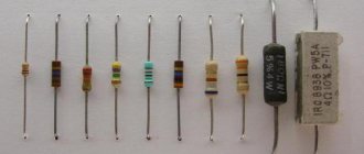
Suddenly, a problem arose: resistors with a power of up to 2 W do not indicate their power. And all because their power is determined by their size:
Table size-power of axial (cylindrical) resistors. Starting from 1 W and above, the resistor power in the diagrams is indicated by Roman numerals (I, II, III, V, etc.)
But, everything is not so clear. There are resistors of the same power of different sizes and different powers of the same size:
Axial (with axial leads) resistors with sudden markings on them in watts (W)
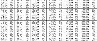
The power of chip resistors is also related to their size:
The right side of the second column (size code, consisting of 4 digits) - encodes the length (first two digits) and width (second two digits) of the part in 1/100ths of an inch (more precisely 1/1000, and between the two digits a decimal is implied dot)
The power values in the third column are indicated at a temperature of 70°C and these are some “standard” values, which are “round” fractions of one watt: 0.031 is 1/32 of a watt, 0.05 is 1/20, 0.063 is 1/16, etc. etc. Also, different manufacturers have resistors of the same size with high power and low power [but flat; Thick Film Chip Resistors].
What is resistor power?
In general, power (measured in watts) is the energy (measured in joules) transmitted (or consumed or released) per second.
The energy of an electric current in a conductor consists of the kinetic energy of the speed of the electrons and their number (current strength, I), and the potential energy of the compression of the electron gas (voltage, U).
The power of the electric current passing through the resistor is determined by the formula P=U·I=R·I2, where U is the voltage drop at the resistor terminals, R is the declared resistance of the resistor.
Electrons crash into the molecules of the semiconductor resistor and heat them (increase the amplitude of oscillations), the energy of the electron current is partially converted into the thermal energy of heating the resistor.
The resistor dissipates this heat into the environment (air), escaping from overheating, and the faster it does this (the more joules of heat per second it releases outside), the greater its power [dissipation] and the more powerful current it can pass through itself.
Accordingly, the more powerful the resistor, the larger the surface of its body (or the radiator to which it is screwed), the colder and denser the environment (air, water, oil), the higher the temperature of heating itself, the loved one, the resistor can withstand.
So, the power of the resistor is the maximum power of the current passing through the resistor, which the resistor can withstand indefinitely without breaking due to overheating and without changing too much its original (nominal; at 25°C) resistance.
How can a resistor break if it is made of materials such as graphite (melting point >3800°C), ceramics (>2800°C), constantan alloy (=1260°C), nichrome, ...? Resistors usually break by cracking their puny body in half or by the caps at the ends falling off (burning off) from the body. Charring paint
A powerful resistor, intact, but the paint on it was charred, so the markings disappeared
is not considered a breakdown. But in order not to lose the marking, it has recently become fashionable to stuff a resistor with a power of ≥ 3 W into a ceramic parallelepiped, which from the outside looks like new even after many years of hard work and heating of the resistor.
Because a powerful resistor gets very hot, essentially a stove, a heating element, it is usually suspended on boards in space on long legs,
Distancing a powerful resistor from the board
to remove from parts on the board, especially from the electrolytic capacitors that quickly dry out over time.
Useful links:
Source: https://almois.ru/moschnost-rezistora-po-razmeru/
Standard sizes of SMD components
Chip components of the same denomination may have different dimensions. The dimensions of an SMD component are determined by its “standard size”. For example, chip resistors have standard sizes from “0201” to “2512”. These four digits encode the width and length of the chip resistor in inches. In the tables below you can see the standard sizes in millimeters.
smd resistors
| Square Chip Resistors and Ceramic Capacitors | |||||
| Standard size | L, mm (inch) | W, mm (inch) | H, mm (inch) | A, mm | W |
| 0201 | 0.6 (0.02) | 0.3 (0.01) | 0.23 (0.01) | 0.13 | 1/20 |
| 0402 | 1.0 (0.04) | 0.5 (0.01) | 0.35 (0.014) | 0.25 | 1/16 |
| 0603 | 1.6 (0.06) | 0.8 (0.03) | 0.45 (0.018) | 0.3 | 1/10 |
| 0805 | 2.0 (0.08) | 1.2 (0.05) | 0.4 (0.018) | 0.4 | 1/8 |
| 1206 | 3.2 (0.12) | 1.6 (0.06) | 0.5 (0.022) | 0.5 | 1/4 |
| 1210 | 5.0 (0.12) | 2.5 (0.10) | 0.55 (0.022) | 0.5 | 1/2 |
| 1218 | 5.0 (0.12) | 2.5 (0.18) | 0.55 (0.022) | 0.5 | 1 |
| 2010 | 5.0 (0.20) | 2.5 (0.10) | 0.55 (0.024) | 0.5 | 3/4 |
| 2512 | 6.35 (0.25) | 3.2 (0.12) | 0.55 (0.024) | 0.5 | 1 |
| Cylindrical chip resistors and diodes | |||||
| Standard size | Ø, mm (inch) | L, mm (inch) | W | ||
| 0102 | 1.1 (0.01) | 2.2 (0.02) | 1/4 | ||
| 0204 | 1.4 (0.02) | 3.6 (0.04) | 1/2 | ||
| 0207 | 2.2 (0.02) | 5.8 (0.07) | 1 | ||
A little educational program for fans of overexposure — DRIVE2
While re-lighting devices, buttons, stoves and other luminous goodies, I often came here without being registered yet, in search of ideas and interesting solutions.
There were a lot of beautiful versions, but in the process of reading many in-flight magazines, I noticed that many authors, when powering LEDs and doing it essentially correctly, are somewhat confused with the markings and types of SMD resistors (just in case for beginners: SMD - Surface Mounted Device - surface mount element).
I was inspired to write this note by an article dedicated to installing an indicator for turning on fog lights in the Kalina-2 instrument cluster. The author, on the whole, did everything correctly, soldered the resistors and the LED into place, but everything worked incorrectly: the rear PTF indicator came on or something like that, I don’t remember exactly.
As a result, the correct result was achieved, according to the author... by installing resistors in strictly defined positions: for one resistor the marking should be directed in one direction, for the other two - in the opposite direction :) Polar resistors :))) But the most interesting thing was next: two photo - on one the resistors are the same, the markings point in one direction, but nothing works, on the second - in different directions (selection of polarity by trial and error) and everything works as it should. Well, I think it's fantastic! However, everything turned out to be outrageously simple: the resistor values in both photos differed from each other by 10 (!) times! Moreover, at the beginning of the article, the author oriented readers: we install resistors of type 101 with a nominal value of 1.2 kOhm (the standard value for the LED circuits of the Kalinovsky tidy). I can imagine the surprise and bewilderment of those who tried to repeat this work and find a resistor of this “type” when they see that resistors of very different sizes have the same markings. I subsequently came across similar errors more than once, so I decided to write this cheat sheet on the types and values of resistors.
So, what is this mysterious “type 101”? These are numbers written on the face of some resistors, but they have nothing to do with the type of element. In relatively large electronic devices (we don’t take mobile phones into account, this is a separate topic), the following types of resistors, or more precisely, standard sizes, are most often used:
SMD resistor sizes
Specialized functional components of surface mount electronic circuits are created using international standards. This approach simplifies design and automated assembly. This publication presents typical sizes of SMD resistors along with a method for identifying individual products.
The small visible surface area means that short coding is necessary
Main sizes of SMD resistors
The limited size of the visible surface explains the minimum number of marking elements. For SMD resistors, the sizes are determined by a digital combination of 4 (5) characters.
The first half of the number indicates the length, the second half the width. Previously, the measurement result was used in inches with rounding of the result.
Nowadays, the metric system (mm) is more commonly used, which means relatively better accuracy.
For your information. To avoid confusion, you must correctly understand the information about the standard size given in the accompanying documentation. Some manufacturers add the letter symbol “M” to the encoding, which denotes the metric measurement method.
Examples of notation
SizeSystem (metric, inch)Length/width
| In inches | In millimeters | ||
| 0201M | M | 0,0079/0,0039 | 2/1 |
| 0805 | D | 0,08/0,05 | 2,032/1,27 |
| 2550M | M | 0,098/0,197 | 2,5/5 |
| 1020 | D | 0,1/0,2 | 2,54/5,08 |
The size of a capacitor, an LED, or an assembly of several resistors is indicated in the same way. As a rule, the thickness is not indicated. This size and other product parameters are given in the accompanying documentation.
For your information. If necessary, detailed information about a specific product can be obtained from the manufacturer’s official website.
Dimensions and technical characteristics of chip resistors
Relatively large products can be measured with a regular ruler. Next, use the reference data to determine the appropriate size. However, as it decreases, solving the problem using available means is much more difficult.
You have to use a micrometer, magnifying glass or specialized magnifying equipment. For example, the dimensions of SMD resistors 0050 (0075) are 0.008 x 0.004 (0.012 x 0.006) inches or 0.2032 x 0.01016 (0.3048 x 0.1524) mm.
It is impossible to determine the difference using a millimeter measuring instrument in this case.
For your information. Marking indicating the standard size is not applied to the body of the SMD resistor.
In order to save space on the printed circuit board, individual resistor models (assemblies) are created with contact pins on the bottom or top pad. This solution provides a connection to the electrical circuit directly at the installation point. The second contact is connected with a separate conductor to a specific section of the circuit.
Chips of the Back Contact category
It is impossible to list all standard sizes within one publication. Specialized enterprises produce various modifications. In some situations, they create unique products according to the customer’s special technical specifications. “Conventional” rectangular and round cross-sectional shapes are used (MELF series).
Electrical resistance is not determined by the size of the chip. Products are produced in a series of ratings from zero value (jumper) to several MOhms.
The miniature pad is suitable for indicating electrical resistance using standard markings (3-4 characters):
- the first digits are the base denomination for calculation;
- the last one is the number of zeros;
- R – comma separator.
Examples:
- 202 – 20*100 = 2 kOhm;
- 4401 – 440*10 = 4.4 kOhm;
- 4R42 – 4.4*100 = 440 Ohms.
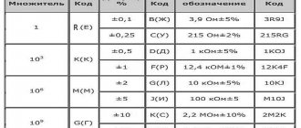
EIA standard markings are also used. The digital code corresponds to a specific denomination. The Latin letter denotes the multiplier. This method is used in the manufacture of precision products with a permissible deviation of no more than 1%.
Parameters that can be found in the detailed description (example for SMD resistor size 0402):
- Length x width – 0.1 x 0.5 mm;
- Thickness – 0.35 mm;
- Electrical resistance (range) – from 1 Ohm to 3 MOhm;
- Nominal accuracy – 1% (5%) for category F (L);
- Power – 0.062 W;
- Operating (maximum) voltage – 50 (100) V;
- Temperature range during operation is from -55°C to +125°C.
The typical dimensions of chip resistors determine the power dissipation for which the corresponding element is designed. To clarify this most important parameter, the methods discussed above for measuring dimensions are used. After this, the permissible power is specified using the reference table (standard size - W):
- 0201 – 0,05;
- 0805 – 0.125 or 0.25;
- 1210 – 0,5;
- 2512 – 1 or 1.5 or 2;
- 1218 – 1.
The list shows that some resistors are produced in different designs. It is recommended to clarify the permissible power in order to exclude excessive current load and damage to the element due to thermal heating.
When choosing, a certain technological reserve is made for this parameter. Please note that the data given in the accompanying documentation corresponds to measurements at a temperature of no more than +70°C.
In this mode, long-term operation is acceptable.
For your information. For assemblies, indicate the overall indicator and power for individual components.
When working with high-frequency (pulse) signals, it is necessary to take into account the influence of reactive components of the structure.
Trimmer SMD resistors
Marking of SMD resistors
Products in this category are available in open and closed versions. Some models are equipped with a sealed housing to ensure long-term performance in conditions of high humidity (dust pollution of the atmosphere).
Trimmer SMD resistors in factory packaging
There is no single standard size for trimmer resistors. Manufacturers independently determine the labeling system and approve the rules with special regulations.
Video
Source: https://amperof.ru/sovety-elektrika/razmery-smd-rezistorov.html
Designation of SMD capacitors
To establish the value of an SMD capacitor, you will need to carefully study its markings. On large-sized elements, as a rule, basic information is applied not only about its denomination, but also the manufacturer’s logo is indicated.
You may be interested in Determining the current or voltage in an outlet
When figuring out the parameters of small bricks, you will have to spend a certain amount of time, because even if the necessary information is available on their body, it is unlikely that you will be able to see the symbols on their surface with the naked eye.
Important! Depending on the type of capacitor, the designations of its parameters may also differ significantly, which must be taken into account in the work.
Marking of ceramic SMD capacitors
Small ceramic SMD capacitors are marked with an alphanumeric code consisting of 3 characters. The first indicates the minimum operating temperature, for example:
- Z - from 10 °C;
- Y - from −30 °С;
- X - from 55 °C.
Marking of SMD capacitors
The second symbol indicates the upper limit of heating of the radio component:
- 2 - up to 45 °C;
- 4 - up to 65 °C;
- 5 - up to 85 °C;
- 6 - up to 105 °C;
- 7 - up to 125 °C;
- 8 - up to 150 °C;
- 9 - up to 200 °C.
The third character indicates the accuracy of the electronic component:
- A - up to ± 1.0%;
- B - up to ± 1.5%;
- C - up to ± 2.2%;
- D - up to ± 3.3%;
- E - up to ± 4.7%;
- F - up to ± 7.5%;
- P - up to ± 10%;
- R - up to ± 15%;
- S - up to ± 22%;
- T - up to ± 33%;
- U - up to ± 56%;
- V - up to ± 82%.
The capacity of small ceramic SMD capacitors is indicated in picofarads. To save the area of a small radio element, the main mantissa number is encoded in a letter of the Latin alphabet. The table below provides a complete list of such designations.
Table with encoded characters
After the number, the multiplier is indicated, for example, the designation on a ceramic capacitor X3 means that the capacitor has a capacity of 7.5 * 10 ^ 3 Pf.
Note! The code indicating the capacity of a ceramic SMD capacitor may be preceded by a Latin letter, which indicates the brand of the manufacturer of the electronic component.
If the area of this type of ceramic capacitor is large enough, then the dielectric type can be displayed on it. For this purpose the following are used:
- NP0. The dielectric constant of such an element is at an extremely low level. The main advantage of components of this type is their good resistance to sudden temperature changes. The disadvantage of elements that use this type of dielectric is their high price;
- X7R. Average quality dielectric. Products that use this type of insulator do not have excellent breakdown resistance characteristics, but in the average temperature range they are able to work significantly longer than many more expensive elements;
- Z5U. A dielectric with high electrical permeability values, but the downside of this indicator is that the capacitance error is too large;
- Y5V. The insulating material has approximately the same characteristics as Z5U. In terms of cost, this dielectric is the cheapest, so electrical components made on its basis are sold at the lowest prices.
You may be interested in this All about selectivity
Burnt SMD capacitor
Considering all of the above, you can be sure that if the SMD capacitor has not burned or changed the color of the surface for other reasons, then you can always determine its value by the markings on its body.
Marking of electrolytic SMD capacitors
Electrolytic capacitors of this type, as a rule, are relatively large in size, so many parameters of such elements are indicated without encryption. That is, the maximum voltage value will be indicated by the number and letter “V”, and the capacitance will be mF.
Marking of electrolytic SMD capacitors
In some cases, the SMD value of an electrolytic type capacitor may also be encoded. Typically, 4 characters (one letter and 3 numbers) are used for this purpose. The first character is the voltage in volts:
- e 2.5;
- G 4;
- J 6.3;
- A 10;
- C 16;
- D 20;
- E 25;
- V 35;
- H 50.
Note! The next three digits encode information about the capacitance of the capacitor (2 digits + multiplier).
Thus, even very small electrolytic SMD capacitors can be marked with information about the main parameters of the product.
SMD resistors - marking codes for SMD resistors
SMD resistors - marking of chip resistors
SMD resistors - the markings of which are of interest to many radio amateurs. These resistors are manufactured in miniature packages, usually made of ceramic and intended for surface mounting. This element is the most common component in modern electronic circuits.
Various companies producing SMD resistors make many different modifications of their products, code designations of which differ from others. In this regard, electronics engineers who often have to repair electronic equipment or assemble printed circuit boards need to clearly know the code designations of resistors.
SMD element housings by power
In the rightmost column you can see the dissipated rated power of the resistor, that is, the power with which the resistor can operate for a long time and without problems.
Now about the labeling. With it, everything is somewhat more complicated, since despite the same type and the same resistor, the markings can be either in inches or in millimeters. therefore, the markings in the figure can be considered incomplete.