What is a resistor
The simplest definition looks like this: a resistor is an element of an electrical circuit that resists the current flowing through it. The name of the element comes from the Latin word “resisto” - “I resist”; radio amateurs often call this part “resistance”.
Let's look at what resistors are and what resistors are needed for. Answers to these questions imply familiarity with the physical meaning of the basic concepts of electrical engineering.
To explain the principle of operation of a resistor, you can use an analogy with water pipes. If you somehow impede the flow of water in a pipe (for example, by reducing its diameter), an increase in internal pressure will occur. By removing the obstacle, we reduce the pressure. In electrical engineering, this pressure corresponds to voltage - by making it difficult for the flow of electric current, we increase the voltage in the circuit, reducing the resistance, we also lower the voltage.
By changing the diameter of the pipe, you can change the speed of water flow; in electrical circuits, by changing the resistance, you can regulate the current strength. The amount of resistance is inversely proportional to the conductivity of the element.
The properties of resistive elements can be used for the following purposes:
- converting current into voltage and vice versa;
- limiting the flowing current to obtain its specified value;
- creation of voltage dividers (for example, in measuring instruments);
- solving other special problems (for example, reducing radio interference).
You can use the following example to explain what a resistor is and why it is needed. The familiar LED glows at low current, but its own resistance is so low that if the LED is placed directly in the circuit, then even at a voltage of 5 V the current flowing through it will exceed the permissible parameters of the part. From such a load the LED will immediately fail. Therefore, a resistor is included in the circuit, the purpose of which in this case is to limit the current to a given value.
All resistive elements belong to passive components of electrical circuits; unlike active ones, they do not release energy into the system, but only consume it.
Having understood what resistors are, it is necessary to consider their types, designation and markings.
Do you want to understand what is needed in a particular case?
How do you know which resistor is needed when creating circuits? Initially, you should understand that knowledge of the current strength or the value of the load resistance is mandatory. Within the framework of the article, two options for influencing the characteristics of the circuit will be considered:
1) If nothing is known, then take a variable resistor and connect it in series with the load. We rotate the regulator until we have the desired voltage. Now, instead of a variable resistance, we connect a constant one with the necessary parameters. Measure the current that comes after the resistor and multiply the resulting value with the voltage that is supplied. Then we will know how much and where to submit.
2) It is necessary to know the previously specified current and load values. To increase the accuracy of the calculation, it is also desirable to know the value of the internal resistance of the power source.
Let's simulate slightly different conditions of action. There is one resistor as a load, Ohm's law and the need to calculate the resistance required for the circuit
This is quite an interesting point and deserves attention. Why was this particular wording chosen? The fact is that people who are just starting to create circuits very often ask this question
But, alas, the line of reasoning they follow is a bit flawed. It will not be possible to calculate the required value using Ohm’s law alone. It is necessary to additionally use the formula for calculating the additional resistor: SDB = CH(NIP-NN)/NN=CH(x-1). Let's look at the formula:
SDB – resistance of additional resistor;
NIP – power source voltage;
CH – load resistance;
X = NPC/NN;
LV is the voltage that needs to be obtained at the load.
Let's use this formula. Let's assume that with a resistance of 1 ohm, the SDB will be 0.6 ohms. If we set it to 5 ohms, the end result will be 3.3 ohms. Why is this so? This is due to the fact that the lower the load resistance, the greater the current characteristic in the circuit. In this case, the power source will sag, because it also creates certain interference with the flow of current. And considering that the voltage will also drop with this, it turns out that an additional resistor with lower characteristics is needed to obtain the desired voltage. This tension is literally “on your fingers.” It may be difficult to understand what and how, but give it a try.
Types of resistors
Types of resistors can be divided into the following categories:
- Unregulated (permanent) - wire, composite, film, carbon, etc.
- Adjustable (variable and adjustable). Trimmer resistors are designed for tuning electrical circuits. Elements with variable resistance (potentiometers) are used to adjust signal levels.
A separate group is represented by semiconductor resistive elements (thermoresistors, photoresistors, varistors, etc.)
The characteristics of resistors are determined by their purpose and are specified during manufacture. Among the key parameters:
- Nominal resistance. This is the main characteristic of the element, measured in ohms (Ohm, kOhm, MOhm).
- Permissible deviation as a percentage of the specified nominal resistance. Indicates the possible spread of the indicator, determined by the manufacturing technology.
- Power dissipation is the maximum power that a resistor can dissipate under long-term load.
- Temperature coefficient of resistance is a value showing the relative change in the resistance of the resistor when the temperature changes by 1°C.
- Limit operating voltage (electric strength). This is the maximum voltage at which the part maintains its declared parameters.
- Noise characteristic is the degree of distortion introduced by a resistor into the signal.
- Moisture resistance and heat resistance are the maximum values of humidity and temperature, exceeding which can lead to failure of the part.
- Voltage factor. A value that takes into account the dependence of resistance on applied voltage.
Its parameters and designation in the diagram
A resistor serves to limit the current in an electrical circuit, create voltage drops in its individual sections, etc. There are a lot of applications, it’s impossible to count them all.
Another name for a resistor is resistance. In fact, this is just a play on words, since in translation from English resistance is resistance (to electric current).
When it comes to electronics, you can sometimes come across phrases like: “Replace the resistance”, “Two resistances have burned out”. Depending on the context, resistance may refer specifically to an electronic part.
In the diagrams, a resistor is indicated by a rectangle with two terminals. On foreign diagrams it is depicted a little differently. The “body” of the resistor is indicated by a broken line - a kind of stylization of the first examples of resistors, the design of which was a coil wound with a high-resistance wire on an insulating frame.
Next to the symbol, the type of element ( R ) and its serial number in the circuit (R 1 ) are indicated. Its nominal resistance is also indicated here. If only a figure or number is indicated, then this resistance is in Ohms. Sometimes, Ω is written next to the number - so the Greek capital letter “Omega” stands for ohms. Well, if so, - 10 k , then this resistor has a resistance of 10 kilo Ohms (10 k Ohms - 10,000 Ohms). You can read about multipliers and prefixes “kilo” and “mega” here.
Do not forget about variable and tuning resistors, which are becoming increasingly rare, but are still found in modern electronics. I have already talked about their structure and parameters on the pages of the site.
Basic parameters of resistors.
Nominal resistance.
This is the factory resistance value of a particular device; this value is measured in Ohms (derivatives of kiloOhm - 1000 Ohm, megaOhm - 1000000 Ohm). The resistance range extends from fractions of an Ohm (0.01 - 0.1 Ohm) to hundreds and thousands of kiloOhms (100 kOhm - 1 MOhm). Each electronic circuit requires its own sets of resistance values. That is why the spread of nominal resistance values is so large.
Semiconductor resistors
These are semiconductor devices with two terminals, which have a dependence of electrical resistance on environmental parameters - temperature, illumination, voltage, etc. For the manufacture of such parts, semiconductor materials doped with impurities are used, the type of which determines the dependence of conductivity on external influences.
The following types of semiconductor resistive elements exist:
- Linear resistor. Made from lightly alloyed material, this element has a low dependence of resistance on external influences over a wide range of voltages and currents; it is most often used in the production of integrated circuits.
- A varistor is an element whose resistance depends on the electric field strength. This property of a varistor determines the scope of its application: for stabilizing and regulating the electrical parameters of devices, for overvoltage protection, and for other purposes.
- Thermistor. This type of nonlinear resistive elements has the ability to change its resistance depending on temperature. There are two types of thermistors: a thermistor, whose resistance decreases with increasing temperature, and a posistor, whose resistance increases with temperature. Thermistors are used where constant control over the temperature process is important.
- Photoresistor. The resistance of this device changes under the influence of light flux and does not depend on the applied voltage. Lead and cadmium are used in manufacturing; in a number of countries this was the reason for refusing to use these parts for environmental reasons. Today, photoresistors are inferior in demand to photodiodes and phototransistors used in similar components.
- Strain gauge. This element is designed in such a way that it is capable of changing its resistance depending on external mechanical influence (deformation). Used in units that convert mechanical effects into electrical signals.
Semiconductor elements such as linear resistors and varistors are characterized by a weak degree of dependence on external factors. For strain gauges, thermistors and photoresistors, the dependence of the characteristics on the influence is strong.
Semiconductor resistors in the diagram are indicated by intuitive symbols.
Photos of resistors
Read here! Surge protection - classification of devices, connection diagrams, features of electrical installation work
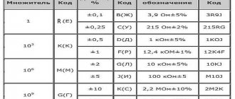
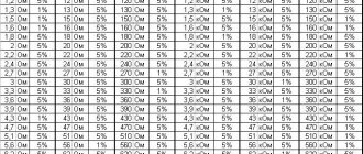
Denominations
There are standard resistance values for resistive elements called "resistor ratings". The approach to creating this series is based on the following consideration: the step between values must cover the permissible deviation (error). Example - if the element rating is 100 Ohms, and the permissible deviation is 10%, then the next value in the series will be 120 Ohms. This step allows you to avoid unnecessary values, since adjacent values, together with the spread of error, practically cover the entire range of values between them.
Manufactured resistors are combined into series that differ in tolerances. Each series has its own nominal series.
Differences between series:
- E 6 - tolerance 20%;
- E 12 - 10% tolerance;
- E 24 - tolerance 5% (sometimes 2%);
- E 48 - tolerance 2%;
- E 96 - 1% tolerance;
- E 192 - tolerance 0.5% (sometimes 0.25%, 0.1% and lower).
The most widespread series E 24 includes 24 resistance values.
How to determine by appearance
The circuit diagram shows the required resistor power - everything is clear here. But how can you determine the resistance power by its appearance on the printed circuit board? In general, the larger the case size, the more heat it dissipates. On fairly large resistances, the nominal resistance and its power in watts are indicated.
There is some confusion here, but it's not all that bad. On domestic resistances they put the letter B next to the number. In foreign ones they put W. But these letters are not always there. In imported ones there may be a V or SW before the number. Imported ones may also have the letter B, but domestic MLTs may have nothing or the letter W. A confusing story, of course. But with experience, at least some clarity appears.
But there are small resistors on which even the nominal value can hardly fit. In imported ones it is applied with colored stripes. How can you find out their dissipation power?
In the old GOST there was a table of correspondence between sizes and capacities. Domestic resistors are still made in accordance with this table. By the way, there are also imported ones, but they are slightly smaller in size than domestic ones. However, they can also be identified. If you are in doubt about which group a particular specimen belongs to, it is better to assume that it has a lower ability to dissipate heat. There is less chance that the part will burn out soon.
| Resistor type | Diameter, mm | Length, mm | Power dissipation, W |
| Sun | 2,5 | 7,0 | 0,125 |
| ULM, VS | 5,5 | 16,5 | 0,25 |
| Sun | 5,5 | 26,5 | 0,5 |
| 7,6 | 30,5 | 1 | |
| 9,8 | 48,5 | 2 | |
| 25 | 75 | 5 | |
| 30 | 120 | 10 | |
| CMM | 1,8 | 3,8 | 0,05 |
| 2,5 | 8 | 0,125 | |
| MLT | 2 | 6 | 0,125 |
| 3 | 7 | 0,125 | |
| 4,2 | 10,8 | 0,5 | |
| 6,6 | 13 | 1 | |
| 8,6 | 18,5 | 2 |
It seems clear with the sizes of the resistances and their power. Not everything is so simple. There are large resistors with low dissipation capacity and vice versa. But in such cases, this parameter is indicated in the labeling.
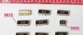
Power of SMD resistors
SMD components are designed for surface mounting and have miniature dimensions. The power of SMD resistors is determined by size. It is also in the specifications, but you need to know the series and manufacturer. The power table for SMD resistors contains the most common values.
| Code imperial | Metric code | Length inch/mm | Width inch/mm | Height inch/mm | Power, W |
| 0201 | 0603 | 0,024/0,6 | 0,012/0,3 | 0,01/0,25 | 1/20 (0,05) |
| 0402 | 1005 | 0,04/1,0 | 0,02/0,5 | 0,014/0,35 | 1/16 (0,062) |
| 0603 | 1608 | 0,06/1,55 | 0,03/0,85 | 0,018/0,45 | 1/10 (0,10) |
| 0805 | 2112 | 0,08/2,0 | 0,05/1,2 | 0,018/0,45 | 1/8 (0,125) |
| 1206 | 3216 | 0,12/3,2 | 0,06/1,6 | 0,022/0,55 | 1/4 (0,25) |
| 1210 | 3225 | 0,12/3,2 | 0,10/2,5 | 0,022/0,55 | 1/2 (0,50) |
| 1218 | 3246 | 0,12/3,2 | 0,18/4,6 | 0,022/0,55 | 1,0 |
| 2010 | 5025 | 0,20/2,0 | 0,10/2,5 | 0,024/0,6 | 3/4 (0,75) |
| 2512 | 6332 | 0,25/6,3 | 0,12/3,2 | 0,024/0,6 | 1,0 |
In general, this type of radio elements has no other operational way of determining the current at which they can operate, other than by size. You can recognize them by their characteristics, but finding them is not always easy.
Marking
The size of the resistive element is directly related to its dissipation power; the higher it is, the larger the dimensions of the part. If it is easy to indicate any numerical value on the diagrams, then marking products can be difficult. The miniaturization trend in electronics production necessitates the use of ever smaller elements, which increases the complexity of both applying information to the case and reading it.
To facilitate the identification of resistors, alphanumeric markings are used in Russian industry. Resistance is designated as follows: the numbers indicate the value, and the letter is placed either behind the numbers (in the case of decimal values) or in front of them (for hundreds). If the value is less than 999 Ohms, then the number is written without a letter (or the letters R or E may appear). If the value is indicated in kOhm, then the letter K is placed after the number, and the letter M corresponds to the value in MOhm.
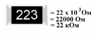
American resistor values are indicated by three numbers. The first two of them involve the denomination, the third - the number of zeros (tens) added to the value.
In the robotic production of electronic components, the printed symbols often end up on the side of the part that faces the board, making the information impossible to read.
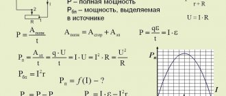
How to calculate the power of a resistor in a circuit
To calculate the power of resistors in a circuit, in addition to resistance (R), you need to know the current strength (I). Based on these data, the power can be calculated. The formula is usual: P = I² * R. The square of the current strength is multiplied by the resistance. We substitute the current strength in Amperes, the resistance in Ohms.
If the denomination is written in kilo-ohms (kOhm) or mega-ohm (mOhm), we convert it to Ohms. This is important, otherwise the number will be wrong.
For example, consider the diagram in the figure above. A series connection of resistances is characterized by the fact that the same current flows through each individual resistor in the circuit. This means the resistance power will be the same. Series connected resistances are simply summed up: 200 Ohms + 100 Ohms + 51 Ohms + 39 Ohms = 390 Ohms. We calculate the current using the formula: I = U/R. We substitute the data: I = 100 V / 390 Ohm = 0.256 A.
Based on the calculated data, we determine the total power of the resistances: P = 0.256² * 390 Ohm = 25.549 W. The power of each resistor is calculated in the same way. For example, let's calculate the power of resistor R2 in the diagram. We know the current, its nominal value too. We get: 0.256A² * 100 Ohm = 6.55 W. That is, the power of this resistor must be at least 7 W. It’s definitely not worth taking with a lower power - it will quickly burn out. If the design of the device allows, then you can install a resistor of higher power, for example, 10 W.
For a parallel connection, the calculation is similar. You just need to correctly calculate the current, but that’s a topic for another article. And the formula for calculating the power of a resistor does not depend on the type of connection.