Sometimes it is necessary to connect the electrodes of a device or element to a DC power source. They are connected, observing polarity. Cathode and anode are the names of the conductors (electrodes) of the device with which this connection is made. There is no clear definition of these two terms. They are distinguished depending on the chemical and physical processes in which these designations are used.
Anode and cathode
Concept of cathode and anode
In electrical engineering, the terminal connected to the positive terminal of the power supply (PS) is called the anode (A). The electrode connected to the minus terminal of the IP is the cathode (K). Translated from Greek, anode means “ascending, upward movement,” and cathode means “descending, downward movement.” These names can be found in such sections of physics and chemistry as:
- galvanic power supplies;
- electrolysis and electroplating;
- semiconductors and vacuum electronics.
In addition, these terms denote the terminals of elements on the circuits and the signs of their charge.
Designation in electrochemistry and non-ferrous metallurgy
Cathode - definition and practical application
The concept of anodes in electrolytic processes applies to positively charged electrodes. Electrolysis, by which various chemical elements are isolated or purified, is the effect of electric current on an electrolyte. Electrolytes are solutions of salts or acids. The other electrode involved in this reaction is the cathode.
Attention! A reduction reaction occurs at the negatively charged cathode (K), and an oxidation process occurs at the anode (A). In this case, “A” can be partially destroyed, participating in the purification of metals from unwanted additives.
In the metallurgical industry, anodes are used when applying protective layers to a product using the electrochemical method (plating) or electro-refining. Electrical cleaning allows you to dissolve rough metal (with impurities) on “A” and deposit it on “K” in a purified form.
A number of commonly used anodes are made of metals:
- zinc;
- copper;
- nickel;
- cadmium;
- lead (an alloy of lead and antimony);
- silver;
- gold;
- platinum.
Nickel plating, galvanizing and other application of protective or aesthetically sought-after coatings on products are carried out mainly from base metals.
With the help of “A” from precious metals, the electrical conductivity of components of electrical products is increased and layers of precious metals are applied to jewelry.
For your information. The pure metal deposited on the cathode is also called the "cathode". For example, pure copper obtained in this way is called “copper cathode”. Then it is used to make copper foil, wire and other things.
Metal refining
Processes occurring during electrolysis
Electrolysis has become widespread in the metallurgy of non-ferrous metals and in a number of chemical industries. Metals such as aluminum, zinc, and magnesium are produced mainly by electrolysis. In addition, electrolysis is used for refining (purifying) copper, nickel, lead, as well as for producing hydrogen, oxygen, chlorine and a number of other chemicals.
The essence of electrolysis is the separation of particles of a substance from the electrolyte when direct current flows through an electrolytic bath and their deposition on electrodes immersed in the bath (electroextraction) or the transfer of substances from one electrode through the electrolyte to another (electrolytic refining). In both cases, the goal of the processes is to obtain the purest possible substances that are not contaminated with impurities.
Any vacuum device has an electrode designed to emit electrons. This electrode is called the cathode. The electrode designed to receive electrons emitted by the cathode is called an anode. A higher and more positive potential relative to the cathode is applied to the anode.
In contrast to the electronic electrical conductivity of metals, ionic electrical conductivity is observed in electrolytes (solutions of salts, acids and bases in water and some other solvents, as well as in molten compounds). Electrolytes are conductors of the second kind. In these solutions and melts, electrolytic dissociation takes place - decomposition into positively and negatively charged ions.
Chemistry of electrolysis.
If electrodes connected to an electrical energy source are placed in a vessel with an electrolyte - an electrolyzer, then an ionic current will begin to flow in it, and positively charged ions - cations will move towards the cathode (these are mainly metals and hydrogen), and negatively charged ions - anions ( chlorine, oxygen) - to the anode. At the anode, the anions give up their charge and turn into neutral particles that settle on the electrode. At the cathode, cations take electrons from the electrode and are also neutralized, settling on it, and the gases released on the electrodes rise to the top in the form of bubbles.
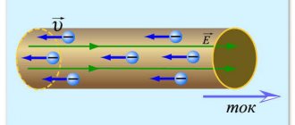
Electric current in an external circuit represents the movement of electrons from the anode to the cathode. In this case, the solution becomes depleted, and to maintain the continuity of the electrolysis process it is necessary to enrich it. This is how certain substances are extracted from the electrolyte (electroextraction). If the anode can dissolve in the electrolyte as the latter becomes depleted, then its particles, dissolving in the electrolyte, acquire a positive charge and are directed to the cathode, on which they are deposited, thereby transferring material from the anode to the cathode. Since in this case the process is carried out so that the impurities contained in the anode metal are not transferred to the cathode, this process is called electrolytic refining.
If an electrode is placed in a solution with ions of the same substance from which it is made, then at a certain potential between the electrode and the solution, neither the electrode dissolves nor the substance is deposited from the solution on it.
This potential is called the normal potential of a substance. If a more negative potential is applied to the electrode, then the release of a substance will begin on it (cathodic process), but if it is more positive, then its dissolution will begin (anode process). The value of normal potentials depends on the ion concentration and temperature. The normal potential of hydrogen is generally considered to be zero. In table Table 1 shows the normal electrode potentials of some aqueous solutions of substances at +25° C.
It will be interesting➡ What is static electricity and how to get rid of it
If there are ions of different metals in the electrolyte, then the ions that have a lower negative normal potential (copper, silver, lead, nickel) are released first at the cathode; alkaline earth metals are the most difficult to separate. In addition, in aqueous solutions there are always hydrogen ions, which will be released earlier than all metals that have a negative normal potential, therefore, during the electrolysis of the latter, a significant or even most of the energy is spent on the release of hydrogen.
Two oppositely polar electrodes
By means of special measures, it is possible to prevent the evolution of hydrogen within certain limits, but metals with a normal potential of less than 1 V (for example, magnesium, aluminum, alkaline earth metals) cannot be obtained by electrolysis from an aqueous solution. They are obtained by decomposition of molten salts of these metals. Normal electrode potentials of substances are minimal; at them the process of electrolysis begins; in practice, large potential values are required for the development of the process.
The difference between the actual potential of the electrode during electrolysis and its normal potential is called overvoltage. It increases energy losses during electrolysis. On the other hand, by increasing the overvoltage for hydrogen ions, it is possible to hinder its separation at the cathode, which makes it possible to obtain by electrolysis from aqueous solutions a number of metals that are more negative than hydrogen, such as lead, tin, nickel, cobalt, chromium and even zinc. This is achieved by conducting the process at increased current densities at the electrodes, as well as by introducing certain substances into the electrolyte.
This is interesting! All about semiconductor diodes.
The course of cathodic and anodic reactions during electrolysis is determined by the following two Faraday laws.
- The mass of the substance me released during electrolysis at the cathode or transferred from the anode to the electrolyte is proportional to the amount of electricity Iτ passing through the electrolyte: me = α/τ, here a is the electrochemical equivalent of the substance, g/C.
- The mass of a substance released during electrolysis with the same amount of electricity is directly proportional to the atomic mass of substance A and inversely proportional to its valence n: me = A / 96480n, here 96480 is the Faraday number, C x mol-1.
Thus, the electrochemical equivalent of a substance α = A / 96480n is the mass of a substance in grams released by a unit of electricity passing through the electrolytic bath - a coulomb (ampere-second).
For copper A = 63.54, n =2, α =63.54/96480-2= 0.000329 g/C, for nickel α =0.000304 g/C, for zinc α = 0.00034 g/C . In fact, the mass of the released substance is always less than indicated, which is explained by a number of side processes taking place in the bath (for example, the release of hydrogen at the cathode), current leaks and short circuits between the electrodes. The ratio of the mass of the actually released substance to its mass, which should have been released according to Faraday’s law, is called the current output of the substance η1.
Therefore, for a real process me = η1 x (A / 96480n) x It. Naturally, always η1<1. The current efficiency depends significantly on the current density at the electrode. As the current density at the electrode increases, the current efficiency increases and the efficiency of the process increases.
The voltage Uel, which must be supplied to the electrolyzer, consists of: decomposition voltage Ep (the potential difference between the anodic and cathodic reactions), the sum of the anodic and cathodic overvoltages, the voltage drop in the electrolyte Ep, the voltage drop in the electrolyte Ue = IRep (Rep is the resistance of the electrolyte), the voltage drop in the electrolyte Ue = IRep (Rep - electrolyte resistance), drop voltage in busbars, contacts, electrodes Uс = I(Rш+Rк+Re). We get: Uel = Ep + Ep + Ue + Uс.
Galvanic circuit device.
The power consumed during electrolysis is equal to: Reel = IUel = I(Ep + Ep + Ue + Uc). Of this power, only the first component is spent on carrying out reactions, the rest are thermal losses of the process. Only during the electrolysis of molten salts is part of the heat released in the electrolyte IUe used usefully, since it is spent on melting the salts loaded into the electrolyzer.
It will be interesting➡ What is electrical resistance
The efficiency of an electrolysis bath can be assessed by the mass of the substance in grams released per 1 J of energy expended. This value is called the energy output of the substance. It can be found by the expression qe = (αη1)/Uel100, here α is the electrochemical equivalent of the substance, g/C, η1 is the current output, Uel is the voltage on the electrolyzer, V.
Anode and cathode in vacuum electronic devices
Characteristics of in5822 Schottky diodes
An electron tube is the simplest vacuum device. It consists of the following parts:
- cathode;
- grids;
- anode.
These three elements make up a vacuum diode. It has a cylindrical “K”, inside of which there is a filament. It heats up “K” to increase thermionic emission. In such devices, electrons leave “K” and travel to “A” in a vacuum, thereby creating an electric current. The anode is the electrode of the lamp with a positive potential. It is made in the form of a box surrounding the mesh and “K”. It can be made of molybdenum, tantalum, graphite, nickel. Its design is different, sometimes it has fins for heat removal.
The grid is an element located in the middle that controls the flow of particles. Most often it is made in the form of a spiral wrapping around the cathode.
Important! The larger the surface area of the cathode, and the hotter it is, the more current flows through the lamp.
“A” and “K” for a vacuum diode
Types of diodes
All diode elements can be divided into 2 large groups: non-semiconductor and semiconductor. The first group consists of 2 types: vacuum (kenotrons) and gas-filled (zener diodes with glow or corona discharge, ignitrons and gastrons).
Vacuum diodes are lamps with two electrodes, one of them is made in the form of an incandescent filament. When opened, electrons move from plus to minus. When the direction of current flow changes, the device closes almost completely and the movement of electrons stops.
Of the gas-filled diode elements, currently only arc discharge gastrons (zener diodes) filled with inert gas and mercury vapor and equipped with oxide thermal cathodes are used. The main feature is the ability to produce high output voltage and work with currents of several tens of amperes.
Semiconductor diodes are small containers from which air has been removed.
There are 2 electrodes placed inside:
- positive (with electrical conductivity p);
- negative (with electrical conductivity n).
Important! The on-state resistance depends on the magnitude of the forward voltage - the higher it is, the lower the resistance.
Anode and cathode in semiconductor devices
What is a diode - operating principle and device
Semiconductor elements conduct electricity in a specific direction. If we consider a semiconductor diode, then its electrodes are also called “cathode” and “anode”. When a direct voltage is applied to it: a positive charge to the anode, the diode is open. If a positive potential comes to the cathode, the diode is closed. Such a diode has a pn junction between these two regions and is picky about the applied polarity. The output of an element from the p-region is called “A”, from the n-region - “K”.
Semiconductor diode
Anode and cathode sign
Which sign is indicated by “K”, which “A”, depends on what procedure and in what area is being considered. In electrochemistry, there are two devices that have different symbols: an electrolyzer and a galvanic cell.
During electrolysis (redox chemical interaction under the influence of an external IP), the minus “-” denotes the cathode. It is on it that metals are reduced due to an excess of electrons. The plus “+”, in turn, marks the anode (positive electrode), where metals are oxidized due to a lack of negatively charged particles.
Signs of charges during electrolysis
In a galvanic cell, oxidation occurs without external influence of electricity. If we take a copper-zinc battery as an example, a large number of electrons (minus) accumulate at the anode. When moving along the external chain, they participate in the reduction of copper. This means that in this case the positive electrode will be the cathode.
Attention! In galvanic cells, the plus is the cathode, the minus is the anode. In electrolyzers, it’s the other way around—the anode is considered a plus, and the cathode is considered a minus.
Charge signs for a galvanic battery
For semiconductor devices, both the sign and the term are clearly assigned to the pins of the part. The anode is the “plus”, the cathode is the “minus” of the diode.
Why is there confusion?
Everything happens because there is no clear connection between minus and plus to the components called “K” and “A”. Michael Faraday also came up with a simple polarity marking rule for this pair of electrodes. What is an anode, according to his explanation? When memorizing the definition, the scientist suggested drawing an analogy with the Sun. Where the current enters (rising) is the anode, where the current leaves (sunset) is the cathode. For batteries, the polarity at the anode and cathode changes depending on whether it operates as a galvanic cell (when discharging) or as an electrolyser (when charging).
DC welding also ambiguously determines “A” and “K” when igniting the arc with direct or reverse polarity.
Signs “A” and “K” for DC welding
How to determine what is minus and what is plus (for a diode)
The peculiarity of diodes is that they conduct charge in only one direction. To avoid mistakes, there are usually markings on the body. In the absence of markings, to find out how to determine the polarities of the anode and cathode of diodes, use the following methods.
- Using a multimeter. The device switches on to test mode. If digital values light up on the screen, the diode is connected via a direct route. The red wire goes to the anode “+”, the black wire to the cathode “-”.
- External signs:
- symbols “+” and “-” on the body;
- closer to the anode there are markings in the form of dots or ring lines;
- the elongated shape of the device is a plus, the flattened shape is a minus;
- Turning on the power. A simple circuit is assembled, which consists of a battery and a lamp.
You might be interested in this: Features of electrical power
Note! If you turn on a light bulb and it starts to light up, the “+” of the battery is connected to the positive polarity, this is the anode, and the device will pass current through itself. If the light does not light up, it means that it is connected to negative polarity - this is the cathode and, accordingly, there will be no current.
- User manual. The manufacturer, along with the product, encloses detailed technical documentation, which specifies all the necessary parameters.
Determining poles using a light bulb
How to determine anode and cathode
What a cathode and anode are is clarified in particular moments: when determining the terminals of semiconductor elements or when identifying electrodes in electrochemical processes.
A semiconductor diode requires positional placement in electrical circuits. For correct connection it is necessary to identify the pins. This can be done according to the following criteria:
- markings applied to the element body;
- length of part leads;
- tester readings when taking measurements in ohmmeter mode or checking diodes;
- using a current source with known polarity.
Marking of semiconductors of this type can be done by applying a graphic designation of a diode to the housing. Then minus (K) is the output from the side of the vertical line into which the arrow outline rests. The diode leg from which the arrow comes out is the plus (A). This is how the forward direction of the current is graphically indicated - from “A” to “K”.
Another way to designate the anode of a diode element can be one or two colored dots or a pair of narrow rings applied to the body. There are structurally designed diodes in which the negative (cathode) terminal is marked with a wide silver ring. The 2A546A-5 (DM) diode serves as such an example.
Examples of marking diodes
The length of the LED legs, which have never been soldered into boards, can also indicate the polarity of the leads. For LED diodes, the long leg is the positive electrode, and the short leg is the negative terminal. In addition, the shape of the body (the edge of the circle) can serve as a guide.
Polarity of LED diode terminals
When using a multimeter to determine the polarity of the contact terminals of a semiconductor, connect it in diode testing mode. If numbers appear on the display, it means the diode is connected in the forward direction. In this case, the red probe is connected to the anode “+”, the black one is connected to the cathode “-”.
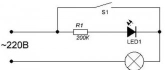
If you don’t have a tester at hand, you can determine the names of the diode terminals by assembling a series circuit from a battery, a light bulb and a diode. When switched on directly, the light bulb will light up, which means that the batteries are plus on the anode and similarly minus on the other electrode.
Information. The LED electrodes can be identified using a constant voltage supply with a known polarity and a current-limiting resistor connected in series. The glow of the element will indicate direct switching. For this purpose, you can take a 3 volt RG2032 battery and a 1 kOhm resistor.
Turning on an LED via a limiting resistor
As for semiconductors, there is always a strict correspondence of names. In other cases, correct determination of the ongoing electrochemical reactions will help to clearly navigate the identification of electrodes.
How to determine where is the anode and where is the cathode?
When determining the cathode and anode, you must first focus on the direction of the current, and not on the polarity of the power source. Despite the fact that these concepts are closely related to the polarity of the current, they are more determined by the directions of the electricity vectors.
For example, in batteries, when recharging, the roles of the cathode and anode change. This is due to the fact that during charging the direction of the electric current changes. The electrode that acts as an electrode when the battery is operating in power source mode during charging performs the functions of a cathode and vice versa - the cathode turns into an anode.
In Fig. 1, the electrolysis process is depicted, during which the movement of anions (negative ions) and cations (positive ions) occurs. Anions rush towards the anode, and positive cations move towards the cathode.
Rice. 1. Electrolysis
During electrolysis, charge carriers of different signs move, however, by definition, the anode is the electrode into which current flows. In the figure, the anode is connected to the positive pole of the current source, which means that current conditionally flows into this electrode.
Pay attention to Figure 2, which shows a diagram of a galvanic cell.
Rice. 2. Galvanic cell
The positive terminal of the current source is the cathode, and not the anode, as one might expect. By carefully studying the operating principle of a galvanic cell, you can understand why the anode is the negative pole.
Pay attention to the diagram of the structure of a galvanic current source. The arrows (above) indicate the direction of movement of electrons, but the direction of current is conventionally considered to be movement from plus to minus. That is, when the circuit is closed, the current enters precisely the negative pole, which is the anode on which the oxidation reaction occurs. In other words, the current from the positive electrode passes through the load to the anode, which is the negative pole of the galvanic cell. With a thoughtful approach, everything falls into place.
When determining the positions of the anode and cathode in radio-electronic elements, reference materials are used.
The purpose of the electrodes is indicated by:
- body shape (Fig. 3);
- lead length (for LEDs) (Fig. 4);
- marks on the housings of devices or the anode mark;
- different thickness of diode leads.
Rice. 3. Diode
Rice.
4. LED electrodes Determining the pin assignments of semiconductor diodes can be determined using measuring instruments. For example, all types of diodes (except zener diodes) conduct current in only one direction. If you connect a tester or ohmmeter to a diode and it shows insignificant resistance, then the anode is connected to the positive probe of the device, and the cathode is connected to the negative probe.
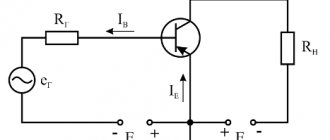
If the conductivity type of the transistor is known, then using the same tester you can determine the emitter and collector terminals. Between them, the resistance is infinitely high (there is no current), and between the base and each of them there will be conductivity (only in one direction, like a diode). Knowing the type of conductivity, by analogy with a diode, you can determine where the anode is and where the cathode is, and therefore determine the terminals of the collector or emitter (see Fig. 5).
Rice. 5. Transistor on the circuits and its electrodes
As for vacuum diodes, they cannot be checked by measuring with conventional instruments. Therefore, their pins are located in such a way as to eliminate connection errors. In electronic tubes, the terminals exactly match the location of the contacts of the socket intended for this radio element.
Video
Coffee capsule Nescafe Dolce Gusto Cappuccino, 3 packs of 16 capsules
1305 ₽ More details
Coffee capsules Nescafe Dolce Gusto Cappuccino, 8 servings (16 capsules)
435 ₽ More details
Stabilizers for smartphones
