Direct start
It involves connecting the stator windings to the electrical network without “intermediaries”. Suitable for motors with squirrel-cage rotor. These are low-power motors in which, when the stator windings are connected directly to the electrical network, the resulting starting currents do not cause overheating, which can damage the equipment.
In asynchronous motors, the ratio of winding inductance to resistance (L/R) is small. And the smaller the power of the device, the smaller it is. Therefore, during startup, the resulting free current quickly decays and can be neglected. Only the current strength that is established as a result of the transient process will be taken into account.
figure (a) is a diagram of a magnetic starter, indicated by the letter K. Technically, this is an electromagnetic switch, often used when starting squirrel-cage electric motors. It is necessary for automatic acceleration according to a natural mechanical characteristic (denoted by M ) from the beginning of the launch (point P ) until the moment when M becomes equal to the moment of resistance ( Ms ).
Picture (b) shows a graph of the starting current versus the initial torque. Based on it, the acceleration acceleration is equal to the difference between the abscissas of the graphs M and M(c) . In this case, if Mstart is less than Ms , then the electric motor will not be able to accelerate. Mstart value for acceleration for a motor with a squirrel-cage rotor, use the formula (slip coefficient s is equal to unity):
The ratio of Mstart to the nominal ( Mnom ) is a value defined as a multiple of the initial torque. Denoted kpm . The coefficient for engines with a squirrel-cage rotor is in the range from 1 to 1.8 and is established by GOST.
Example. If kpm = 1.4, and Mnom = 5000 N*m, then direct start should begin with MP = 7000 N*m.
Attention! The standards established by GOST must not be exceeded. This leads to an increase in active resistance on the rotating element of the motor.
Direct engine starting has the following advantages:
- Cheapness;
- Simplicity;
- Minimal heating of the windings during startup.
Disadvantages of the method:
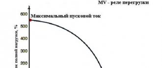
- The value of Mstart is up to 300% of Mnom ;
- The starting current is up to 800% of the rated current (see graphs below).
Even with the listed disadvantages, direct starting remains the most preferable for asynchronous electric motors with a squirrel-cage rotor, because provides high energy performance.
Undervoltage starting
Suitable for starting high-power electric motors, but also optimal for medium-power analogues if the voltage in the operating network does not allow accelerating the motor using direct starting.
There are three ways to reduce voltage:
- Switching the stator windings from triangle (normal circuit) to star (starting circuit). Starting starts from star, and when the rated frequency is reached, it switches to delta. In this case, the voltage supplying the phases of the stator windings drops by 1.73 times. This allows phase currents to decrease by the same amount, and linear currents are reduced by three times.
- Starting with additional resistance leading to a drop in voltage on the stator winding (Figure a). At the time of start-up, reactors or resistors are included in the electrical circuit (reactive and active resistance, respectively).
- Start with connection via a step-down transformer with several automatically switched stages (Figure b).
The main advantage is the ability to accelerate the engine at almost the same voltage that is necessary for normal operation. The only disadvantages include a drop in MP and Mmax (maximum moment). These values are directly proportional to the voltage: the lower the Volt, the smaller the torque. Therefore, the motor will not start with a load.
Starting up an asynchronous motor with a squirrel-cage rotor
To start an asynchronous motor with a squirrel-cage rotor, the following methods are used:
· starting with a reduced supply voltage.
40.2.1. Direct connection
Direct connection of an asynchronous motor to the network is the simplest way to start the motor. At the same time, in this case, the stator and rotor windings of the motor are flown by a large starting current (short-circuit current), equal to 4-7 times the rated value. Therefore, it is very important that the engine starting time is as short as possible. This starting method is used for small motors, or for motors that rotate small mechanical loads.
40.2.2. Low voltage starting
Starting at reduced supply voltage is usually carried out in cases where direct starting is not allowed due to network operating conditions.
Typically, one of four reduced voltage starting methods is used:
- engine through a step-down autotransformer;
- switching the stator winding from star to triangle;
- turning on the engine through a semiconductor voltage regulator.
In all these cases, a decrease in voltage leads not only to a proportional decrease in the starting current (positive effect), but also to a sharp (quadratic) decrease in the starting torque (negative effect).
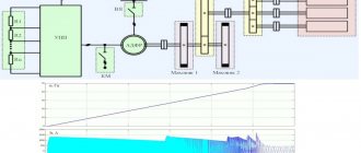
a) Starting an asynchronous motor through an autotransformer
In Fig. 40.1. shows a diagram of starting an asynchronous motor through an autotransformer.
Fig.40.1. Starting an asynchronous motor using an autotransformer
Reducing the voltage at start-up can be achieved by connecting a step-down autotransformer T (Fig. 40.1). When starting, switch QS1 is first closed, and the reduced voltage reaches the motor windings. When the rotor reaches a sufficient rotation speed, switch OS2 is closed, shunting the autotransformer so that the full network voltage reaches the motor windings.
b) Start with switching of stator windings from star to triangle
Starting methods with reduced voltage also include starting with switching the stator windings from star to delta (Fig. 40.2).
Fig.40.2. Motor starting circuit with winding switching from star to delta
In start mode, the QS is in position
, and the stator winding is connected according to a star circuit. After the rotor reaches a steady rotation speed, the switch must be moved to position and the stator windings will be switched on in a delta pattern.
With this starting method, the voltage supplied to each phase of the motor is actually reduced, since at the same mains voltage the phase voltage in the star circuit is
times less than in the triangle diagram. The starting current in the network when connecting the stator winding and star is reduced by a factor of 10 compared to the starting current when connecting in a delta. However, the starting torque, proportional to the square of the voltage, is reduced by 3 times.
Date added: 2014-12-24; ; ORDER A WORK WRITING
Source
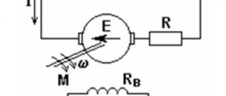
Connecting the rotor to the rheostat during switching on
The method is suitable for switching on motors with a wound rotor. If the rotor circuit includes a rheostat, then the active resistance increases. In this case, point K in figure a below moves closer to O and is designated K` . This does not lead to a decrease in Mmax , but it does provide an increase in Mstart . At the same time, the critical slip increases, and the dependence of the moment on s shifts to the zone of large slips. The number of revolutions shifts to the zone of lower rotational frequencies (Figures b and c).
Typically, the rheostat used to start the motor has from 3 to 6 stages (see figure a below). The starting resistance gradually decreases, which ensures a large Mstart . Initially, the motor is driven according to the fourth characteristic, illustrated in Figure b . It matches the resistance of the starting rheostat and provides maximum starting power.
Torque ( Mvr ) decreases with increasing speed. At a certain minimum value, it is necessary to turn off part of the rheostat so that Mvr increases again to the maximum (see the third characteristic). But the revolutions are increasing, so Mvr decreases again. Then another part of the rheostat is turned off, and work on the second characteristic begins. When the rheostat of a wound-rotor motor is turned off completely, the starting process is completed. The motor continues to operate according to characteristic 1.
Launching using this method is characterized by a change in Mvr from the maximum to the minimum value. The resistance in this case decreases stepwise along a broken curved line (highlighted in bold on the graph). The rheostat parts are turned off automatically or manually.
The advantage of starting an electric motor with a wound rotor using a rheostat is the ability to turn it on at Mstart close to Mmax . Inrush currents are minimal. The change in current strength is illustrated in Figure c.
There are plenty of shortcomings. The first is the difficulty of inclusion. Secondly, this is the need to use not at all cheap motors with a wound rotor. The nature of the operation is worse than that of analogues with a squirrel-cage rotor with the same power value - this is the third disadvantage. This explains why electric motors with a wound rotor are used mainly in case of difficulties with starting other motors.
Starting a single-phase motor
To turn on an asynchronous motor powered from a single-phase network, auxiliary winding is used. It should lie perpendicular to the working stator winding. But to create a rotating magnetic field, one more condition must be met. This is the phase shift of the current flowing through the auxiliary winding relative to the current arising in the working winding.
To ensure a phase shift at the time of connection to a single-phase network, a special element is included in the electrical circuit of the auxiliary winding. This could be a resistor, capacitor or inductor. But only the first two are common elements.
After accelerating the motor to a frequency equal to the established frequency, the additional winding is turned off. This can be done manually or automatically. At the beginning, the motor operates according to a two-phase characteristic, and after setting the frequency, according to a single-phase characteristic.
How are asynchronous motors driven?
The simplest way to start asynchronous motors is to directly connect them to the network. However, as it was found out, at the moment of starting a large
starting current. In low-power networks, this current can cause a short-term drop in voltage, which has a detrimental effect on the operation of some energy receivers included in this network.
In order to reduce the starting current, special methods of starting motors are used in practice.
Let's look at the simplest of them.
Starting engines using a starting rheostat in the stator circuit.
The rheostat is connected in series with the stator windings (Fig. 5-15).
At start-up, the rheostat is fully inserted, and then, as the rotor accelerates, manually or automatically (centrifugal starters) it is removed, while the resistance of the rheostat reduces the current, but this leads to a decrease in torque. This method can only be used in cases where the engine is started without load. This method is uneconomical, especially for high-power engines due to the high energy consumption in the starting rheostats. Currently, current regulation using thyristors is widely used for these purposes.
Starting motors by switching windings from star to delta. At the moment of start-up, the stator windings are turned on as a star until the rotor speed is close to the nominal one, and then the connection of the windings is switched to a triangle (Fig. 5-16). The starting current is reduced by three times. Let's show it.
Let the line voltage of the network
, and the total resistance of each of the motor windings. Let's find the starting current (current in the linear wire) when connected by a star and a triangle.
For the case of star connection, the phase voltage
this is the starting current, since for a star
.
For the case of a triangle connection
and phase current
This is the inrush current for the delta connection.
This method can be used only in cases where the motor has all six ends of its windings brought out, the motor windings can be connected to this network in a triangle, and when the electric motor is started without load or with a load of no more than 40% of the rated load.
Source
Applying resistance at start
The method is applicable for asynchronous motors connected to a single-phase network and having a primary additional winding with a squirrel-cage rotor. This is the name given to a split-phase motor, the electrical circuit of which has a high active resistance.
To start a motor powered from a single-phase network, a starting resistor is needed, connected in series with the additional winding. Then the phase shift is 30 degrees. This is enough for overclocking. Below is a diagram according to which an ohmic phase shift is achieved.
Instead of a resistor, you can use an additional winding of high resistance but low inductance. In this case, the winding has few turns, which are made from wire of a smaller cross-section, in contrast to what is used for working winding.
In Russia, motors come off the assembly line connected to a single-phase network, equipped with a phase shift resistor. Their power varies in the range of 18-600 W. The motors are designed for networks with a voltage of 127, 220 or 380 Volts and alternating current with a frequency of 50 Hz.
Using a capacitor
The method differs from the previous one in that a split-phase motor, when connected to a single-phase line, has a high resistance only at the time of start-up.
To ensure the highest value of Mstart, a circular and rotating magnetic field is required. To do this, the currents in the working and additional windings are shifted by 90 degrees. Only a capacitor can provide such a bias. Its use helps to achieve good starting performance of an asynchronous motor powered from a single-phase electrical network.
The choice of starting method for an asynchronous electric motor depends on which network it is connected to: single-phase or three-phase. The power of the motor and its design also influence.
More on the topic: - Connection diagrams for asynchronous and synchronous single-phase motors - Connection diagrams for an electric motor via capacitors - Reversible diagram for connecting an electric motor - Do-it-yourself soft start of an electric motor - What is the difference between asynchronous and synchronous motors - Reversible connection of a single-phase asynchronous motor with your own hands - How to check an electric motor - Electric motor repair
SOFT START OF AN INDUCTION MOTOR
A logical way to reduce the starting current was to reduce the voltage supplied to the stator at the time of starting, with its gradual increase as the engine accelerates.
The simplest and oldest method of soft starting is rheostat starting of an electric motor: several powerful resistors are connected in series to the stator circuit, which are sequentially short-circuited by contactors.
High inductance chokes (reactors), as well as autotransformers, can also be used.
This soft start method has obvious disadvantages:
Automation is problematic.
The operation of contactors is not tied to the real current value; they are either switched manually or switched automatically using a time relay.
Complicated starting under load.
Since the torque of an asynchronous motor is proportional to the square of the supply voltage, a 2-fold reduction in voltage at start-up will result in a 4-fold reduction in torque. The use of soft starting with electric motors directly connected to the load significantly increases the time it takes to reach operating speed.
Improvements in power electronics have made it possible to create compact automatic soft starters (also called soft starters from the English soft start) for asynchronous electric motors, installed on a standard mounting rail of electrical panels.
They provide not only smooth acceleration, but also engine braking, allowing you to adjust the start and stop current parameters in various modes:
Constant current limitation. At the moment of starting, the current is limited to a given excess of the rated value and is maintained at this value throughout the engine acceleration. Typically a limit of 200-300% of the rated current is used. The overload becomes insignificant, although its duration increases. Current generation. In this case, the current curve at the moment the engine is turned on has a greater slope, after which the softstarter goes into current limiting mode.
This soft start method is used when connecting to low-power substations or generators to reduce the starting load, however, the starting torque of the electric motor in this case is minimal. For devices that do not have an idling motor, it is impossible to use current generation with a flat starting curve.
Accelerated start (kick start). It is used with motors that directly drive the load, since otherwise their starting torque may be insufficient to start the rotor.
In this case, the soft starter allows a short-term excess of the starting current several times (in fact, direct switching is carried out); after a specified time, the current is reduced to two to three times the nominal value.
Freewheel stop. When the engine is turned off, the voltage from it is completely removed, and the rotation of the armature continues by inertia. The simplest switching method, applicable for low power and low drive inertia.
However, at the moment the circuit breaks, a strong inductive surge occurs, leading to strong sparking in the contactors. On powerful electric motors, as well as at high operating voltages, this shutdown method is unacceptable.
Linear voltage reduction. Used to stop the engine more smoothly. It must be remembered that the engine torque decreases nonlinearly due to the quadratic dependence of torque on voltage, that is, the decrease in torque occurs most sharply at the beginning of the curve.
Power is turned off at a minimum current in the winding; accordingly, the switching switches are practically not worn out by the formation of a spark between the contacts.
To reduce loads during shutdown, controlled voltage reduction is used:
- At first, the current decreases minimally;
- then the curve begins to decline steeper.
The reduction in electric motor torque is close to linear. This method of controlling the stopping of an electric motor is used in devices with high drive inertia.
When using this type of soft starter, commissioning work consists of setting the desired type of starting current curve and, in the case of using current generation or accelerated start modes, setting the duration of the time interval of the initial section of the curve.
The use of soft starters allows you to automate the starting mode, but its main disadvantage remains - either you have to build into the device the ability to idle the electric motor, or allow short-term network overloads by spinning up the motor and load with a kick start.