Installation of frequencies in lathes
In this article I will tell you about the installation of frequency converters, or frequency converters, in lathes with 1.1 kW motors.
The machines are more likely to be amateur or school ones, their productivity is low, but for the garage or for making crafts from metal or wood as a hobby - just right. This is the first time I’m installing an inverter into lathes, and I’m grateful to Alexander for his advice.
The first machine had a special feature: it is connected to a single-phase network at the request of the client. There are no options here, you need to connect through a single-phase inverter, because the version with a capacitor greatly loses power (motor efficiency drops) and does not have speed control. But the speed needs to be changed, because not all speeds can be switched through the gearbox - it is partially broken and not all speeds can be switched on.
Connection diagram of the machine to the electrical network.
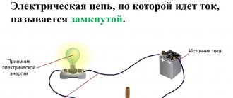
Connecting machines to the electrical network is a fairly simple procedure, but requires special care and caution.
This article will help you do it correctly and avoid serious mistakes. The machine connection diagram will be similar for different types of equipment, but there are some nuances that are worth considering. The article will also be useful for those who are interested in connecting 3-phase 220 V equipment. In this article we will look at connecting to a three-phase and single-phase network, as well as many related issues: Wire markings:
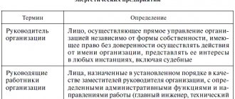
The three-phase power supply system is the most common. Almost all industrial equipment is powered from a 380 V network, except for amateur and desktop machines. The three-phase machine is connected to the electrical network using a cable with marked conductors. There are several standards for marking such wires and terminal connectors; all options are presented in the table:
Marking on the machine:
The electrical cabinet nameplate should contain basic information about the power supply to the equipment. This information is not always available, so we can often observe the situation of connecting lathes designed for 220 V, bypassing the standard step-down transformer, which certainly leads to serious problems. We will talk about the correct actions in this situation a little further, but for now we will look at the case when there is a nameplate.
Wire connection location in the machine:
If you don't know where to connect the power, then the first thing you should find is the hole for the wire. It is usually located at the bottom of the electrical cabinet and has a sealed entry. In the photo you can see the connection diagram for a CNC lathe. A 4-wire wire (3 phases and ground) is inserted from the bottom of the electrical cabinet and connected to the terminal block.
As a rule, the thickest wires will be laid to this terminal block at the other end. If you couldn’t find it right away, then pay attention to the main switch on the electrical cabinet. The wires coming out of the top of this switch go to the contacts of the input terminal block. If you could not find the connection point, then most likely the wire goes directly to the input switch. In this case, 3 phase wires are connected to the switch, and the yellow-green wire is connected to the ground bus. Example (with non-compliance with colors) in the photo:
Connecting a 220 V machine to a 220 V network:
For example, if you need to connect a single-phase drilling machine to a 220 V network, then you just need to have a regular grounded outlet in the room. One phase (L1), a neutral wire (N) and a ground wire (PE) are connected to the socket. The voltage between phase and zero is exactly 220 V. Typically, such equipment already has a wire with a plug.
Conventional electrical appliances are designed to be powered from a single-phase circuit, this is done for economic reasons. Therefore, domestic premises (apartments, offices and garages) in 99% of cases are connected to only one of the phases.
Connecting a 380 V machine to a 380 V network:
Connecting a 3-phase machine to a 380 V network is the simplest case. We connect the wire as described earlier, observing the phase sequence. If you are not sure of the phase sequence in the panel, you can simply connect them at random. If, after connection, the electric motors (coolant motor, conveyor) rotate in the opposite direction, then you have not guessed correctly with the phasing, and you need to swap any two phases. If the switched-on hydraulic station shows “zero” on the pressure gauge, this also indicates an incorrect phase sequence. The 4-wire connection option is shown in the figure:
READ How to properly connect the power supply to a computer video
There are cases when production uses a 5-wire power system (L1, L2, L3, N, PE), but the electrical diagram for the machine only indicates grounding - there is no neutral. Then the neutral wire is connected to the grounding terminal, and the grounding wire is attached directly to the equipment housing:
If a 5-wire circuit is used in the electrical panel and in the machine (less common), then we connect as follows:
Connecting a 380 V machine to a 220 V network:
Not the easiest connection method, requiring a slight modification in the wiring of the electrical cabinet. Let’s immediately make a reservation that connecting an industrial CNC machine will not work this way, but connecting a 380 V drilling machine to a single-phase network is quite possible. In this article we will not talk about turning on asynchronous motors using a phase-shifting capacitor. When turned on in this way, the engine loses 50% of its power and torque. In practice, it turns out that a 1 kW motor is not suitable even for woodworking. In the end, most craftsmen simply refuse to use such equipment.
The most correct scheme for connecting a machine designed for 380 V to a 220 V network is implemented using a frequency converter. For example, you have a TV-4 lathe - connecting it to a single-phase network is possible, but the frequency converter will need to be installed directly in front of the engine. Such a frequency converter is inexpensive and will cost in the range from 10,000 to 15,000 rubles. As a bonus, you will get the ability to smoothly adjust the rotation speed! To do this, you will have to “slightly alter” the electrics. Below is the original electrical diagram for connecting the machine and the diagram converted for a frequency converter:
The diagram is for informational purposes only and may vary depending on the type of frequency converter. Before purchasing, you must read the documentation for the device.
A simpler task is to connect the sharpening machine, since in essence it is a regular asynchronous motor (without wiring), and the frequency converter can be installed directly at the input.
The case when there is no nameplate on the machine:
It would seem that the case is extremely clear. If this is an industrial machine, and we see a terminal for connecting using a 4-wire circuit (L1, L2, L3, PE), then we connect it to 3 phases 380 V and it’s done! This is exactly what many illiterate electricians do in factories when they see a modern bar machine for the first time.
It is worth noting that there are a number of CNC machines (very often these are bar machines) that are connected to a three-phase voltage of 220 V. These machines are supplied with a transformer. In this case, the transformer is connected to the electrical panel, and the machine is connected to the transformer using a standard cable. You can determine at what voltage the machine operates (if the nameplate is lost) by the method of connecting the motor windings; to do this, just open the cover of any asynchronous motor on the machine and look at the connection diagram. Motors for 380 V are connected in a star, and from 220 V - in a triangle.
READ How to connect an iPhone camera to a computer via USB
Conclusion:
In this article, we familiarized ourselves with almost all the options for connecting various equipment. As you may have noticed, connecting 380 V machines is usually not a problem, and you can do it yourself, observing safety precautions. But connecting a 3-phase machine to a 220 V network is not an easy task. The engineers working in our company will help you cope with this task. We wish you success, and don't forget to buy a fire extinguisher!
Source
First machine, single-phase
A Delta VFD015M21B frequency drive was installed in the first machine.
Delta 1.5 kW inverter for installation in a lathe
This is a budget model with an output power of 1.5 kW, but it has universal power supply; it can be powered from one or three phases. Which is exactly what we need. The photo shows the power connection terminals and ground:
Delta inverter, power inputs R, S, T
Output terminals - for three-phase electric motor:
IF outputs terminals for connection
Optionally, a brake can be connected.
The peculiarity is that if we connect one phase, then we have a voltage of 220V at the input. This means that the maximum we get at the output is also 220V. Therefore, the motor is needed for 220 V.
At the inverter input there is a phase voltage of 220 V (star circuit, with a solidly grounded neutral, our usual electrical network). The output is three-phase linear 220 V (“Triangle”, no neutral). Read more about how phase voltage 220 V differs from linear voltage 380 V.
If the motor is 220/380 V, then it must be connected to a 220 V triangle. If the motor is 380/660 V, then it will not be suitable for power supply from a 220 V inverter. I wrote about this in more detail in the article about Connecting a motor according to the “Star-Delta” scheme.
Therefore, the connection was simple, phase and zero to the first two terminals:
Power supply to the inverter 220 V for the first two phases
Connecting terminals to the motor and control:
Frequency driver connection of output terminals for the motor (three black wires at the bottom) and control terminals
Low-current control terminals of the inverter, bottom view
As a result, the connection looks like this:
Installing a frequency generator in a single-phase lathe
Despite the fact that there are buttons and a smooth speed control on the front panel of the inverter, it is not used because it is installed in a closed cabinet. To control the speed and start of the engine, there are buttons on the control panel of the lathe, and wires go to them.
Motor winding connection diagrams
In three-phase asynchronous electric motors, two connection options are used - star and delta. In three-phase asynchronous electrical machines, depending on the model, it is possible to implement the following scheme:
The simplest way to determine the capabilities of a particular asynchronous electric motor is to look at the nameplate (a metal plate with technical parameters). They also indicate the operating voltage rating for the corresponding connection. Here the designation can be indicated only for a star, only for a triangle, or both options at the same time; an example of such marking is shown in the figure below:
Example of designation on a nameplate
If the nameplate is missing or the information on it has been erased, then the connection diagram can be found by opening the winding start distribution block (BRNO). If you see 6 pins with terminal connections, you can determine the type of connection of the windings. It is much worse when the boron has only three terminals, and the connection is made inside the housing. In this case, you need to disassemble the three-phase electric motor to see the connection method.
Star
The star connection diagram for a three-phase motor provides that the beginning of each winding is combined into one point, and phases from the supply line are connected to their ends. This type provides a much smoother start and relatively gentle operation. However, the power with which the rotor rotates is one and a half times lower than when connected by a triangle. Schematically, this connection looks like this:
Star connection diagram
As you can see in the figure, the ends of the terminals of the three-phase motor windings A2, B2, C2 are connected into one electrical unit. And phase wires are connected to terminals A1, B1, C1, usually 220 or 380 volts.
If we consider this circuit using the example of Born, it will look like this:
Star connection of windings
Triangle
To connect an electric motor with a triangle, you need to bring the end of one winding to the beginning of the other. And thus close the windings into a kind of ring, at the connection points of which the leads of the supply line are connected. The triangle connection scheme provides maximum torque and force on the shaft, which is especially important for heavy loads. However, the current in the windings at rated load will also increase proportionally, not to mention overload conditions.
Therefore, turning on a three-phase motor with a delta requires a voltage reduction. For example, if the same electrical machine can be connected with both a triangle and a star winding connection, then the star will have a supply voltage of 380, and the triangle 220 volts or 220 and 127 volts, respectively. Schematically connecting the windings with a triangle will look like this:
Triangle connection diagram
As you can see, the connection is made from A2 to B1, from B2 to C1, from C2 to A1, in some models of electrical machines the markings of the terminals may differ, but on the cover of the burner their affiliation to a particular winding and possible options for connecting to each other will be displayed.
Triangle connection of windings
Second machine, three-phase inverter power supply option
The second machine needs to be powered from three phases, so there are fewer restrictions on the choice of motor. If anything, the same motor as in the first machine must be connected according to the “Star” circuit at 380 V.
The inverter was installed with Innovert ISD, a complete analogue of the 1.5 kW Delta inverter.
Three-phase converter Innovert-ISD 1.5 kW
The photo has not been saved, but I will give a diagram that is identical for the first and second options, only differences in the number of power phases and a little in the name of the terminals.
Inverter in a lathe, circuit diagram for connecting the power section
Everything is clear from the diagram, I’ll just explain that cooling in such machines is almost never used due to low productivity, but it is available as an option. The light switch is present on the lamp itself.
The control part looks like this:
Control circuit for a lathe on a frequency converter
For such a scheme, the front panel of the machine had to be slightly modified in order to install the necessary buttons. In the frequency settings, you need to set the control mode with reverse so that the Forward and Backward buttons work.
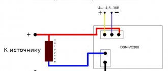
The speed is also controlled using the + and - buttons. The output frequency is set from 20 to 60 Hz, it can be changed as needed, depending on the processing mode of the parts. To control the frequency, I bought a digital voltmeter for the front panel from radio products.
Voltmeter for monitoring the rotation speed of a lathe drive
In order for the voltmeter to show something adequate, I configured the analog output FOV of the inverter in such a way that 60 Hz (the maximum possible speed) is 6 Volts. So 50 Hz is 5 V, etc. True, the voltmeter refuses to show below 3.5 volts - there is not enough power.
You can configure the voltmeter, or rather the output function of the inverter, to read the motor current. This can be important when processing parts. And it won’t hurt to control the overload in your work.
Connection methods and diagrams
Depending on the type of load used for the electric motor, its design features and characteristics, and the desired result, various connection schemes can be used. Most often, capacitors are used to connect a three-phase unit as a single-phase household load, but their number and method of putting them into operation depend on many parameters. Therefore, next we will look at various options for connecting electric motors.
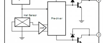
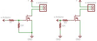
Without capacitors
To connect an asynchronous electric motor to a 220V network, it is not at all necessary to use a capacitive element. Thanks to the development of semiconductor switches and circuits using them, you can avoid unnecessary power losses. For this, a transistor or dinistor switch is used.
Triangle capacitorless starting circuit
The above circuit is designed for starting electric motors with low speeds up to 1500 rpm and relatively low power.
The circuit works as follows:
- when voltage is applied to the input, the wires are connected to two points of the motor;
- voltage is supplied to the third point of the triangle through a timing RC circuit;
- the resistance store R1 and R2 regulates the shift interval by moving the slider;
- after the capacitor in the chain is saturated, dinistor VS1 passes a signal to open triac VS2.
If the connection of an electrical unit involves a large starting load and requires operation at high speeds - up to 3000 rpm, then it is necessary to use a similar electronic key circuit with two triacs and separate timing elements for each of them. But the windings of the electric machine will be connected according to an open star circuit. The operation of the scheme is similar to the previous one:
Capacitorless star starting circuit
With capacitors
Using capacitive elements to connect an electric motor is the most common method. For this, two capacitors are used, one of which is starting and the second is working. The starting voltage is introduced briefly, the additional capacitance allows you to increase the voltage shift in the corresponding winding and create more force.
Connection diagram with capacitors
As you can see from the figure above, a single-phase voltage is supplied to the electric motor between points L and N. The asynchronous motor IM is connected to them with two windings, and the same phase is connected to the third windings through the contacts of the push-button switch SA1 and SA2, which switch parallel-connected capacitors C1 and C2.
Advantages of installing an inverter in a lathe
We can finish the article here, but a couple more phrases on installing an inverter in a lathe. Compared to the contactor switching circuit there are several advantages:
- The frequency converter allows for smooth acceleration and braking of the spindle with the workpiece. And this greatly protects both the mechanics of the machine and the electrics.
- The inverter provides protection for the motor, eliminating the need to install automatic motors and thermal relays, which are also unreliable parts and additional contacts in power circuits.
- The inverter can regulate the speed, which means there is no need for a manual gearbox. And if there is one, the range of adjustments expands several times.
- implementation of reverse with zero effort and free of charge. No need for an expensive reversing contactor or reversing gearbox.
- If you use an inverter with universal power supply, you can not depend on a three-phase network, and install the machine even in an ordinary apartment, powering it from a 220 V outlet.
The disadvantages are a drop in torque and overheating of the engine at low speeds. To avoid this, it is not recommended to exert great force on the workpiece at low speeds. Or install additional cooling. And the best way out is to install a more powerful motor and inverter.
That's all, follow the publications, articles by other Authors will be published soon, and then a vote will be announced. You can check how things are going with the Competition right now by following the link.
If you are interested in the topic of frequency converters, here are several articles on SamElektrika. There you can also find detailed information about the principle of operation, settings, and you can also download literature on the frequency converter.
- Installing a Frequency Converter in a Shoe Polishing Machine
- Installing a frequency converter in a band saw
- Gate control using a frequency converter
- There are also many articles and notes about inverters and industrial equipment in general on the Zen channel SamElectric.ru. For example.