A fan, like any other electrical device, sometimes tends to break down; the stator winding in it most often burns out. But this is not at all a reason to send him into retirement. In this article, we will talk about the practice of repairing household fans.
We begin the disassembly process by removing the fan cover; hidden under it is a small single-phase squirrel-cage rotor with a power of 20 watts. Let me remind you that the rotor is a moving part of an electric motor that rotates due to . Thereby driving the blades of our fan.
The stator is a static winding that is located on the steel core of the electric motor. The stator converts alternating current into a rotating magnetic field.
Upon external inspection, it is of course difficult to break any device if there are no obvious signs of damage that speak for themselves. In our example, we need to test the stator winding and power cord for integrity. The easiest way to do this is with a regular multimeter, which should be in the tool arsenal of any radio amateur. You can learn how to use a multimeter correctly.
After a series of measurements, it turned out that our power cord was in perfect order, and the stator winding of the household fan simply burned out. To repair it yourself, we will need to partially disassemble the engine. The stator winding can be removed quite easily using a regular screwdriver by driving it in with even blows in the places indicated by the arrows in the photo.
After successfully dismantling the stator winding, you can move on to mathematics, namely, calculating the number of turns for the motor stator winding.
For a simplified calculation, you can use the following algorithm as a basis:
The voltage in a normal alternating current network is 220 Volts, the engine power is 20 Watts, the cross-section of the core is 1.2 cm 2, the current passing through the coil will be 0.09 A. (based on the well-known formula I=P/U).
The cross-section of a typical wire can be calculated using the following formula
:
If we convert the cross-sectional area of the wire from 0.03 mm 2 to the diameter of the wire, we end up with: d = 0.19 mm
I borrowed the winding wire from a coil of a magnetic starter with a diameter of 0.17 mm since I don’t know how to lay the required number of turns on the coil frame.
In the latter case: U is the mains voltage, S c is the core cross-section, B c is the magnetic permeability of iron (maximum 14,000 hectares).
As soon as we calculate the number of turns, we can start winding. It is difficult to wind so many turns around the core manually, so I recommend using a homemade one.
After the coil is made, it is necessary to impregnate it with a special impregnation varnish, otherwise the insulation of the wires in it may be damaged.
After the varnish has dried, you need to install the coil back. If, after assembly and testing, problems arise with the direction of rotation of the blades, then you only need to remove the rotor and install it on the other end of the core. Alternatively, you can pull out the stator coil again, rotate it 180 degrees and install it back.
In the figure above, short-circuited turns are marked with red arrows; the magnetic field rotating the blades, which acts on the rotor, will be concentrated on them.
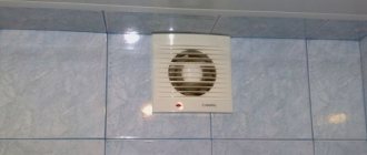
In order to find the cause of the fan failure, it is necessary to disassemble it, as in the previous example. This is quite easy to do. First, we remove the protective grille, then take out the blades or impeller, which is usually secured with a special nut. Then you need to dismantle the other part of the protective grille and unscrew the cover screws.
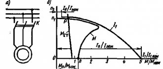
I also recommend studying the typical circuit diagram of a floor fan. Typically, it uses an asynchronous electric motor with 8 windings (working and starting). To successfully start the engine, it is necessary to create a phase shift of 90 degrees. For this purpose, the circuit contains a capacitor. The circuit will work after pressing the power button, the indicator lamp should light up and the blades begin to rotate, the motor rotation speed depends on the connection diagram of the windings, using a switch.
First you need to check the serviceability of the network cable. Then execute to start the engine. It is also recommended to check the integrity of the contacts and wires. If a hum or noise is heard while the fan is operating, then you need to lubricate it with Litol thick lubricant.
Electric motor repair begins with lubrication of the bearings, usually after this the fan begins to work well. Machine oil can be used for lubrication.
A fairly typical malfunction is a break in one of the stator windings. To check, you can sharply rotate the blades in the direction of rotation clockwise. If the fan starts working, it means one of the windings has burned out.
The service life of the electric motor is reduced several times if you do not clean it of dust, or if you forget to lubricate the bearings or gearbox.
No matter how well electrical equipment works, sooner or later it fails. Especially often those devices that are used very intensively break down. These include a household fan. There are various types of breakdowns in this product. When they occur, the owner has no choice but to contact the workshop. However, in some cases you can do it on your own. To do this, it is enough to know well the structure and operating principle of this electrical equipment. Information on how to repair a fan yourself is presented in the article.
Electrical product design
Before you begin repairing a home fan, it is advisable to familiarize yourself with its structure. In this electrical equipment, cooling is carried out due to the rotation of the blades.
The place where they are mounted is a special shaft on cranks, which is driven by a motor. The fans are equipped with electric motors, which, depending on the model, can have different power. They are started using stators. The flanges are used as supports for the contact blocks. The fan can be equipped with a gearbox. It is fixed using a clamping bar. The mechanism is housed in a plastic case on a long stem.
Disassembly
Fan repair requires mandatory disassembly of the equipment. To do this you need to do the following:
- Unscrew the fan cover. This is its front part in the form of a protective mesh.
- Disconnect the propeller. It is mounted on the motor shaft using a nut. Since it has a left-hand thread, you need to rotate the nut clockwise. Upon completion of the fan repair, the nut is installed back by tightening it in the opposite direction.
- Remove another protective mesh. It is secured with a nut at the back of the device.
- Remove the protective cover. It is connected to a handle that adjusts the rotation of the housing in the product using a hidden bolt.
Do-it-yourself computer cooler repair diagram
In computer coolers
Brushless motors are also used, but TWO-PHASE rather than three-phase.
1 - rotor with impeller 2 - stator with winding 3 - control board 4 - permanent magnet in the form of a ring 5 - control chip (with Hall sensor) FS276
Supply voltage - 3.20 V (with separate power supply to the windings and the microcircuit, up to 30 V can be supplied to the windings), maximum continuous winding current - 0.4 A.
If the north N pole of the ring magnet is near the Hall sensor, then the transistor connected to winding 1 is open. If the south S pole of the ring magnet is near the Hall sensor, then the transistor connected to winding 2 is open.
Functional diagram of the FS276 chip
Scheme
turning on
the cooler
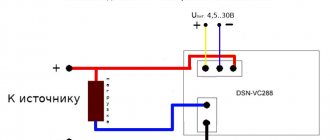
red wire - "plus" supply voltage blue wire - "minus" supply voltage yellow wire - tachometer output.
red wire - "plus" supply voltage blue wire - "minus" supply voltage yellow wire - tachometer output
red wire - "plus" supply voltage blue wire - "minus" supply voltage yellow wire - tachometer output
Source
Engine repair
Fans become very overheated during intensive use. Motor failure is considered one of the most common breakdowns.
Fan repair should begin with an initial inspection. To do this you need:
- Remove the cover with the protective grille.
- Remove the motor. It is secured with four bolts.
- View contacts. If there is darkening on them, the problem should be sought in burnt out contacts. If there are no darkenings, then the master will have to “ring” the engine. A broken motor will make a humming noise.
- Measure the resistance of the stator windings. The normal value is 1.2 kOhm. If the motor hums but does not turn on, it means it needs a new rewind. This can be done in a specialized workshop. Judging by the reviews of some owners who were faced with the problem of a burnt-out engine, it is impossible to independently repair a household fan with such a breakdown. Many consumers advise buying a new engine straight away rather than taking the old one to a mechanic for winding.
How does a computer cooler work?
Computer coolers use brushless motors, but TWO-PHASE motors rather than the more common three-phase motors.
1 - rotor with impeller 2 - stator with winding 3 - control board 4 - permanent magnet in the form of a ring 5 - control chip (with Hall sensor) FS276
Supply voltage - 3.20 V (with separate power supply to the windings and the microcircuit, up to 30 V can be supplied to the windings), maximum continuous winding current - 0.4 A.
FS276 chip pinout:
pin assignment: 1 — “plus” supply voltage (VCC) 2 — collector of the key transistor power supply of winding 1 (NO) 3 — collector of the key transistor power supply of winding 2 (SO) 4 — “minus” supply voltage (GND)
functional diagram of the FS276 chip:
The microcircuit, together with the Hall sensor, controls the switching of the motor windings:
- if the north (N) pole of the ring magnet is located near the Hall sensor, then the transistor connected to winding 1 is open;
- if the south (S) pole of the ring magnet is located near the Hall sensor, then the transistor connected to winding 2 is open.
The cooler is connected as follows: red wire - to the “plus” of the supply voltage (12 V); blue wire - to the “minus” of the supply voltage (12 V); yellow wire - tachometer output.
Source
Repairing the capacitor
The cause of capacitor failure can be sudden surges in voltage in the electrical network. In this case, repairing the fan, as usual, begins with disassembling it. For most models, the condenser is located immediately behind the central flange. To get it, you must first remove the engine and disassemble the power supply. In some fan models, removal of the condenser may be prevented by the presence of a crank, in which the owner will have to remove the flange as well.
In this case, repair of the floor fan will be limited to checking the capacitance of the capacitor. To measure the resistance on the conductors, the home technician will have to use a special tester. If the readings of this device exceed 50 Ohms, then you should purchase a new capacitor.
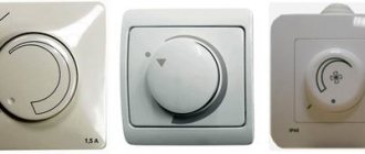
The speed switch is broken
If the fan makes a lot of noise during operation, the first thing the owner should do is check the condition of the product regulator. It is located next to the control unit.
Removing the regulator is simple: just remove the back cover. The control unit will be closed by a contact block. It is also removable. It is advisable that the clamping bar remains intact. After removing the block, you can begin to inspect the regulator. Very often, the cause of a speed switch breakdown can be a disconnected conductor. In this case, it is not difficult to repair the floor fan yourself. Using a blow torch, the DIYer mounts the conductor back into place. It happens that he simply burns out. Then the fan owner will have to get a new conductor.
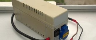
Using an electromagnetic relay
To drive the fan, a DC electric motor with excitation from permanent magnets ME or similar is installed.
We also do not recommend connecting the circuit so that after turning on the ignition the electric fan constantly rotates, as this significantly reduces its service life. Installation and connection of the fan Considering that cars are equipped with fans in normal mode, re-installation may only be necessary during repair work, that is, after replacing broken parts of an old part or when installing a new device.
Then, using the same key, unscrew the bolts securing the radiator tube that connects it to the air conditioning system if, of course, such is provided for by the design of the car and move it to the side. I installed a 30 pin relay in the power circuit. However, it is only in recent years that fan control technology has developed significantly. We also do not recommend connecting the circuit so that after turning on the ignition the electric fan constantly rotates, as this significantly reduces its service life. Source fornk. It is convenient to place the relay on the side surface of the body behind the right headlight, closer to the battery.
The normal operation of the cooling fan remained in place. Operating modes When understanding the operating principle and connection diagram of the radiator fan, you should remember that electric motors often have two speed modes.
Of course, there are certain limits for changing the supply voltage. Turn on the hazard lights, depress the clutch pedal and, using the inertia of the car, try to carefully move to the edge of the roadway and stop as far to the right as possible on the side of the road, and if possible, outside the roadway.
Application of semiconductors Instead of an electromagnetic relay, you can use a thyristor switch, or a design based on field-effect transistors. The block uses small connectors, female 2.8, so in order not to spoil the wire, we make an additional wire on one end, small male 2.8, on the other, female 6.3, using a block for small connectors, connect the wires to each other and connect them to the existing wires. Fan connection
How to repair the control unit?
The most common problem with blocks is broken worm gears. The fan owner will first have to remove the contact block. In this case, it is not necessary to remove the electric motor. Most models of electric fans are equipped with special pads that cover the control units. These pads should be removed. Then, using a screwdriver, you need to completely unscrew the shaft. Only after this is the control unit removed. By removing the back cover, you can see the condition of the worm gear. Below it is a contact shaft. The block resistance is checked by a tester. The resulting parameter should be up to 50 Ohms. If the readings are higher, then such a control unit should be replaced with a new one.
How to replace the rotor?
This procedure is considered rare for ventilators. But still, due to overheating of the electric motor, the rotor may also become unusable. To fix it, the owner first needs to remove the fan cover. The location of the rotor was a special gasket behind the shaft. To get the rotor, you will have to use a screwdriver to remove the electric motor. After this, an initial inspection is carried out. Very often the cause of a breakdown is burnt out wires. If they are ok, then the rotor itself is broken. According to many owners, in this case it should be immediately replaced with a new one. The old gasket can be used. The new rotor must be installed so that it does not come into contact with the electric motor.
If the diffuser is broken
The cause of failure of this element is considered to be twisting of the regulator. Such cases are very rare. Repairs should begin by removing the fan cover. The electric motor can be left in place. However, in order to make it more convenient to work with the control unit, some technicians recommend removing the central flanges from the fans. Otherwise, after repairing the diffuser, installing the unit back in its original place will be problematic. The diffuser is located on the back of the control unit. In some fan models, diffusers are secured using special clamps. The failed element is disconnected from the block using a knife or screwdriver. The technician just needs to slightly pry the diffuser. The faulty element is replaced with a new one.
If the cooling fan does not work
To drive the fan, a DC electric motor with excitation from permanent magnets ME-272 or similar is installed. Technical data of the electric fan and fan switch sensor:
The cooling system fan may not turn on due to:
To check the VAZ fan electric motor itself, we apply 12 V voltage from the battery to its terminals - a working motor will work. If the problem is with the fan, you can try to repair it. The problem is usually the brushes or bearings. But it happens that the electric motor fails due to a short circuit or break in the windings. In such cases, it is better to replace the entire drive.
The BO fuse is located in the mounting block of the car's engine compartment and is designated F7 (20 A). The test is carried out using a car tester turned on in probe mode.
Problems with the blades
Since plastic is used in the manufacture of the blades, this part of the fan is very susceptible to external mechanical influences. As a result, the blades often become deformed and break if any foreign objects get caught behind the mesh. In this case, in order to repair the fan, the owner needs to dismantle the protective mesh. The back cover can remain in place. There is no need to remove it. The protective mesh is held in place by a special clip in the form of a plastic cap. It is easy to turn with just your hands. After the clamp is twisted and the protective mesh is removed, the special lining that secures the blades is detached. This stage of work can be completed without the use of tools. The blades must be replaced if they are very deformed. If during operation of the fan there is slight friction against the protective grille, then they can be easily aligned by hand. According to fan owners, plastic blades bend very easily.
Control circuit modernization
The cooling fan on the top ten turns on at a temperature of 100-105°C, while the normal operating temperature of the engine is 85-90°C, so the fan turns on when the engine overheats, which naturally has a negative effect.
This problem can be solved in two ways: adjust the switch-on temperature in the “brains” or make a button. We'll focus on the second one. Turning on the fan from the button is very convenient: if you get into a traffic jam, turn it on, drive out, turn it off, and no overheating occurs.
A button for selecting the fan operating mode was installed in the cabin (always off, constantly on, automatically turned on via a sensor) - this “tuning” is not mandatory, but will be a very useful addition.
There will be a large current at relay contacts 87, 30, on the wire from the battery to the fuse and the fan ground, and therefore we must use wires there with a cross-section of at least 2 mm, otherwise the thinner wire will not withstand it and will burn out.
If the flange is broken
Since the flanges are made of plastic, this part of the fan is very susceptible to impacts. Flanges become unusable as a result of falling of an electrical product. Repair begins with dismantling the protective cover. In some models, the flanges are located near the electric motors. In this case, there is no need to remove the control units. After twisting the crank and removing the worm gear, the derailleur is disconnected. The location of the flange is a special panel on which it is mounted with four screws.
In some fan models, the flanges are located near the control units. In this case, the owner will first have to remove the clamping bar, and then the block itself. There is a special gasket near the rotor. In order to get to the flange, it must be removed. It is secured with two screws.
Breakdowns that you can fix yourself at home
Fan blade deformation
Happens quite often since the propeller itself is made of plastic. The blades may become deformed when exposed to high temperatures. As a result of deformation, the blades touch the protective mesh, and a characteristic unpleasant noise occurs. Usually the deformation is corrected manually, otherwise the blades and protection will very quickly become completely unusable.
Deformation of the protective fence
It usually appears as a result of a falling floor fan. The fence itself is made of relatively thin metal wire and includes two parts - front and back. The front part is very easy to remove, but the back part will require some fiddling. The propeller is removed from the electric motor shaft, after which the large plastic nut is unscrewed and then the guard itself is removed. After straightening, the protection is assembled in the reverse order.
Turns to the sides stop
The main reason for this could be a disconnected crank. It is necessary to disassemble the device body and tighten the fastening screws if they are loose or unscrewed. In addition, interruptions may occur in the turning mode. To determine the cause, the gear engagement of the gearbox is checked, as well as the operation of the switch. If necessary, the gearbox is lubricated with a special lubricant. In case of severe wear, it is recommended to replace the parts. If there are no replacement parts, the fan can be used in normal mode, without turning on the turns.
Switch fault
May cause interruptions in operation. To check its condition, you need to remove the switch and determine the condition of the contacts. If necessary, the contacts are cleaned with sandpaper.
Fan connection 2108, 2109, 21099
Until 1998, on cars with the old mounting fuse block 17.3722 (finger type fuses), relay 113.3747 was included in the fan circuit. After 1998 there is no such relay.
Also, before 1998, the TM-108 switching sensor was used (the closing temperature of its contacts is 99±3ºС, the opening temperature is 94±3ºС), after 1998 the TM-108-10 with similar temperature ranges or its analogues from different manufacturers. The TM-108 sensor only works in conjunction with a relay; the TM-108-10, reinforced for high current, can work both with and without a relay.
Scheme for switching on the engine cooling fan on a VAZ 2109 with mounting block 17.3722
K9 - Relay for turning on the fan motor. A - To terminal “30” of the generator
Scheme for switching on the engine cooling fan on a VAZ 2109 with mounting block 2114-3722010-60
A - To terminal “30” of the generator