Why can't you control the fan speed with a dimmer?
To regulate the rotation speed of single-phase electric motors with a supply voltage of 220 V, triac rotation speed controllers are used.
The dimmer (triac dimmer), in turn, is designed to control a resistive load and should be used only as a regulator of lamp brightness.
Datasheets and operating manuals usually contain instructions that it is inadmissible to use a dimmer to control the motor.
For example, the description of a 300W dimmer from Eljo (Sweden) states: inductive and capacitive loads (conventional transformers, fluorescent lamps and electric motors) cannot work with these dimmers.
Differences in control schemes:
Dimmers and triac speed controllers use similar control circuits. Both use the principle of phase control, when the moment when the triac is turned on changes relative to the transition of the mains voltage through zero. For simplicity, we usually say that the output voltage changes.
The triac regulator circuit differs from the dimmer circuit in the following ways:
· The lower threshold for the voltage supplied to the fan motor is set
· The power of the triac is selected so that its maximum operating current exceeds the operating current of the fan by at least 4 times. With a resistive load of 2 A, it is enough to take a triac also rated at 2 A.
· The fuse is selected based on the power of the electric motor. Typically, the maximum fuse current should be 20% greater than the motor operating current.
· For more correct formation of a sinusoid, an additional phase-shifting damping capacitor is installed.
An additional noise suppression capacitor is used to reduce network interference
Why is this necessary:
1. The torque of an asynchronous motor decreases in proportion to the square of the applied voltage. When the lower voltage threshold is reached, the engine may not start. For single-phase axial and duct fans, the lower value is 40-60 V.
Due to the fact that the motor is not rotating, it still consumes current, the fan windings begin to heat up. The engine begins to make a characteristic sound (hum). As a result, if the engine is not equipped with reliable internal thermal protection, it burns out within an hour.
In triac regulators, the minimum voltage supplied to the fan is set at the factory. Typically this is 80-100 V. This guarantees normal operation of the fan at low voltages.
2. When starting, the engine briefly consumes current, 6-7 times the maximum operating current (starting current). For reliable operation when starting the engine, a triac with a high operating current is used.
3. To properly protect the motor from overcurrent (overvoltage, overheating of bearings, etc.), the maximum fuse current must be selected according to the type of motor. For triac regulators, this value is 15-20% higher than the maximum motor current.
4. When a reduced voltage is applied, the engine power drops and the rotor begins to slip relative to the stator field. At certain speeds, a phase shift occurs and the engine begins to briefly consume current higher than the maximum operating current. To prevent such a situation, an additional damping capacitor and a more powerful triac are installed in the triac regulator circuit.
5. The shape of a sinusoid during phase control of an inductive load is more complex than when controlling an active load, so an additional capacitor is required to suppress the high-frequency spectrum of interference. The dimmer that controls the fan may cause interference visible on the computer or TV screen.
Often households need to install a fan speed controller. It should be noted right away that a regular dimmer for adjusting the brightness of lighting is not suitable for a fan. It is important for a modern electric motor, especially an asynchronous one, to have a correctly shaped sine wave at the input, but conventional lighting dimmers distort it quite strongly. To effectively and correctly regulate fan speed, you must:
- Use special regulators designed for fans.
- Keep in mind that only special models of asynchronous electric motors can be adjusted effectively and safely, so before purchasing, find out from the technical specifications about the possibility of adjusting the speed using the voltage reduction method.
Description of the operation of the speed controller circuit
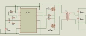
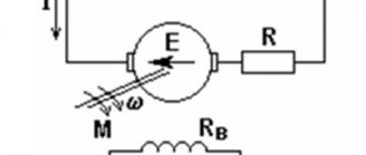
The diagram below of a thyristor speed controller is specifically designed to change the rotation speed of commutator electric motors (electric drill, milling cutter, fan). The first thing to note is that the motor, together with the power thyristor VS2, is connected to one of the diagonals of the diode bridge VD3, while the other is supplied with a mains voltage of 220 volts.
In addition, this thyristor is controlled by fairly wide pulses, due to which short-term shutdowns of the active load, which characterize the operation of the commutator motor, do not affect the stable operation of this circuit.
To control the thyristor VS1 on the transistor VT1, a pulse generator is assembled. This generator is powered by a trapezoidal voltage created as a result of limiting the positive half-waves by a zener diode VD1 having a frequency of 100 Hz. Capacitor C1 is discharged through resistances R1, R2, R3. Resistor R1 controls the discharge rate of this capacitor.
When the capacitor reaches a voltage sufficient to open transistor VT1, a positive pulse is sent to the control terminal VS1. The thyristor opens and now a long control pulse appears at the control pin VS2. And already from this thyristor, the voltage, which actually affects the speed, is supplied to the engine.
The rotational speed of the electric motor is controlled by resistor R1. Since an inductive load is connected to circuit VS2, spontaneous unlocking of the thyristor is possible, even in the absence of a control signal. Therefore, to prevent this undesirable effect, a diode VD2 is added to the circuit, which is connected in parallel to the excitation winding L1 of the electric motor.
Methods for adjusting the rotation speed of household fans
There are quite a few different ways to adjust the fan speed, but only two of them are practically used at home. In any case, you can only reduce the engine speed below the maximum possible according to the device data sheet.
It is possible to accelerate an electric motor only using a frequency regulator, but it is not used in everyday life because it has both a high intrinsic cost and the price of the service for its installation and commissioning. All this makes the use of a frequency regulator not rational at home.
It is allowed to connect several fans to one regulator, unless their total power exceeds the rated current of the regulator. When choosing a regulator, keep in mind that the starting current of the electric motor is several times higher than the operating current.
Ways to adjust fans at home:
- Using a triac fan speed controller is the most common method, allowing you to gradually increase or decrease the rotation speed in the range from 0 to 100%.
- If a 220-volt fan motor is equipped with thermal protection (overheating protection), then a thyristor regulator is used to control the speed.
- The most effective method of adjusting the rotation speed of an electric motor is to use motors with multiple winding leads. But I have not yet seen multi-speed electric motors in household fans. But you can find connection diagrams for them on the Internet.
Very often the electric motor hums at low speeds when using the first two adjustment methods; try not to operate the fan for a long time in this mode. If you remove the cover, then using the special regulator located under it, you can, by rotating it, set the lower limit of the motor speed.
System design
The commutator type motor consists mainly of a rotor, a stator, as well as brushes and a tachogenerator.
- The rotor is part of the rotation, the stator is an external type of magnet.
- Brushes, which are made of graphite, are the main part of the sliding contact, through which voltage is applied to the rotating armature.
- A tachogenerator is a device that monitors the rotation characteristics of a device. If there is a violation in the regularity of the rotation process, then it adjusts the voltage level entering the engine, thereby making it smoother and slower.
- Stator. Such a part may include not one magnet, but, for example, two pairs of poles. At the same time, instead of static magnets, there will be coils of electromagnets. Such a device is capable of performing work both from direct current and alternating current.
Scheme of the speed controller of the commutator motor
Special frequency converters are used in the form of speed controllers for 220 V and 380 V electric motors. Such devices are considered high-tech, and they help to radically transform the current characteristics (signal shape, as well as frequency). They are equipped with powerful semiconductor transistors, as well as a pulse-width modulator. The entire process of operating the device occurs through the control of a special unit on a microcontroller. The change in speed in the rotation of the motor rotor occurs quite slowly.
It is for this reason that frequency converters are used in loaded devices. The slower the acceleration process occurs, the less load will be placed on the gearbox, as well as the conveyor. In all frequency generators you can find several degrees of protection: by load, current, voltage and other indicators.
Some models of frequency converters supply power from a single-phase voltage (it will reach 220 Volts) and create a three-phase voltage from it. This helps to connect an asynchronous motor at home without the use of particularly complex circuits and designs. In this case, the consumer will not lose power while working with such a device.
https://youtube.com/watch?v=EYkb8_6F-Sw
Why use such a device-regulator?
If we talk about regulator motors, the required speed is:
- For significant energy savings. So, not every mechanism needs a lot of energy to perform the work of rotating the motor; in some cases, rotation can be reduced by 20-30 percent, which will help significantly reduce energy costs by several times.
- For the protection of all mechanisms, as well as electronic types of circuits. Using the converter frequency, you can exercise certain control over the overall temperature, pressure, as well as other indicators of the device. In the case when the engine operates as a specific pump, then a specific pressure sensor should be inserted into the container into which air or liquid is pumped. When the maximum mark is reached, the motor will simply automatically stop working.
- For the soft start process. There is no particular need to use additional electronic equipment - everything can be done by changing the settings of the frequency converter.
- To reduce device maintenance costs. With the help of such speed controllers in 220 V engines, the possibility of failure of devices, as well as certain types of mechanisms, can be significantly reduced.
The circuits used to create frequency converters in an electric motor are widely used in most household devices. Such a system can be found in wireless power supplies, welding machines, phone chargers, power supplies for personal computers and laptops, voltage stabilizers, lamp ignition units for backlighting modern monitors, as well as LCD TVs.
Connection diagram for a triac or thyristor fan speed controller
Almost all regulators have fusible switches inside, protecting them from overload currents or short circuits, in the event of which they burn out. To restore functionality, it will be necessary to replace or repair the fusible rate.
The regulator is connected quite simply, like a regular switch. The first contact (with the image of an arrow) is connected to the phase from the apartment's electrical wiring. On the second (with an arrow in the opposite direction), if necessary, a direct phase output is connected without adjustment. It is used to turn on, for example, additional lighting when the fan is turned on. The fifth contact (with the image of an inclined arrow and a sine wave) is connected to the phase going to the fan. When using such a scheme, it is necessary to use a distribution box for connection, from which Zero and, if necessary, Ground are connected directly to the fan, bypassing the regulator itself, which requires only 2 wires to connect.
But if the electrical distribution box is located far away, and the regulator itself is located next to the fan, then I recommend using the second scheme. The power supply cable comes to the regulator, and then goes straight from it to the fan. Phase wires are connected in the same way. And 2 zeros are placed on contacts No. 3 and No. 4 in any order.
Connecting the fan speed controller is quite easy to do with your own hands, without calling specialists. Be sure to study and always follow electrical safety rules - work only on a de-energized section of electrical wiring.
Fan speed controller connection diagram
Exhaust ventilation systems are widely used to provide comfort in residential and utility rooms. Most often, hoods are installed in toilets and bathrooms, as well as in the kitchen. The simplest way to connect a fan involves two positions - on and off. The toilet sometimes uses a switch with a presence sensor - this will save energy if you constantly forget to turn it off.
To increase acoustic comfort (the fan does not have to constantly operate at full power), rotation speed regulators are used.
IMPORTANT! Before purchasing a fan, check with the seller whether its motor is designed to work with a speed controller.
Technical implementation of fan speed control:
- changing the AC frequency of the motor;
- change in supply voltage.
The frequency controller has a number of important advantages. By reducing the fan speed, energy consumption is reduced, that is, this method is the most economical. Also, when using this method, there is no parasitic heating of the motor windings.
Unfortunately, these advantages are negated by the high cost of the device. Therefore, the use of frequency controllers in everyday life is impractical.
How to reduce or increase the speed of the hood fan
In exhaust systems, increasing or decreasing the fan rotation speed allows you to change the flow intensity, which affects the air exchange as a whole. To control it, one of the methods already discussed is used (by changing the voltage or frequency of the current).
In practice, the first of the techniques is used, since the frequency regulator in this case will cost more than the fan itself
The peculiarity of this method is its simplicity and low cost, which is very important for household systems and devices used in public areas
It is possible to increase or decrease the drawing speed using a simple mechanical method. To do this, some types of control modules are equipped with a small wheel, through which the engine speed is changed stepwise or smoothly.
Source
Popular schemes using voltage reduction
The main advantage of such controllers is their low cost, which allows them to be used in everyday life. Disadvantage: poor efficiency. When the speed decreases, only the noise decreases; electricity consumption does not actually change. Another drawback is the inability to connect powerful devices, but for home use this is not critical.
Controller circuit design options:
- step regulators using an autotransformer;
- electronically controlled autotransformers;
- triac or thyristor controllers.
ATTENTION! When using a speed controller, it is necessary to install a fan with a power slightly higher than that for which the room is designed. This will extend its service life.
Step control using an autotransformer
The operating principle of this controller is as follows. A supply voltage of 220 V is supplied to the input of autotransformer T1. The winding has several branches from part of the turns. When connecting the load to the branches, the consumer receives a reduced supply voltage. Using switch SW1, the fan motor M is connected to the desired part of the winding and its rotation speed is changed. When the supply voltage decreases, electricity consumption decreases. The output signal is a pure sine wave, which has a beneficial effect on the condition of the motor winding. The disadvantage is the large size of the control unit. The adjustment knob has a stepped scale, usually no more than five positions. It is impossible to control the rotation speed smoothly.
Autotransformer with electronic control
The electronic autotransformer operates on the principle of pulse width modulation. The transistor circuit, modulating the pulses, smoothly changes the output voltage. The advantages of such a controller are its compact size and low cost. The disadvantage is that the cable length from the controller to the motor is limited. Therefore, the autotransformer unit, as a rule, is made in a separate housing from the control knob and is located in close proximity to the fan.
Triac (thyristor) controller
Without going into details of the phase control principle by which regulators of this type operate, we will briefly describe the circuit. Each thyristor “cuts” half a wave of alternating current, reducing the output voltage. The value is adjusted using the control unit. Advantages: low price, compact size. The speed can be adjusted from almost zero. Disadvantage: sparking of the motor winding, limited load power.
IMPORTANT!
- The fan motor must have automatic thermal protection.
- It is unacceptable to use dimmers for lighting fixtures as a fan speed regulator.
Varieties
Fan speed limiters come in several types.
Stepped models using an autotransformer
The essence of the operation of this device is that the winding of the device is branched, so when connected to the branches, the fan receives a slightly reduced voltage. Using a special switch, one or another fan is connected to the desired section of the winding, and its rotation speed drops. At the same time, electricity consumption is reduced, which leads to overall resource savings.
The device is adjusted using a special handle equipped with a stepped scale with 5 positions. The advantages of the models are their reliability and long service life. The disadvantages include a rather large control unit, which is not always convenient when placing the device in confined spaces, as well as the impossibility of smooth switching. However, by connecting temperature sensors and timers, switching rotation speeds can be automated.
Self-connection of fan speed controller
All household regulators are designed for installation without necessarily inviting an electrician. If you are able to replace a switch or socket, you can do the installation.
Speed controllers are produced in three versions:
Wall mounted for installation without recess.
Wall-mounted for recessed installation.
DIN rail mounted
Installing a recessed wall regulator is the same as installing a regular outlet.
The connection diagram is simple: the contacts are marked, no additional wiring is required. If there was a regular fan switch in this place, you only need to replace it with a regulator.
If the control unit and regulator are made in different housings, additional wiring is required. The power cable is connected to the regulator directly from the electrical panel, and the controller is connected to it with a low-current signal wire.
Video:
- How to properly install a hob into a countertop
- How to install an infrared heater yourself
- How to connect an air conditioner to the power supply yourself
- Connecting a rj11 telephone socket, diagram
Buying a ready-made regulator
The regulators are connected in series in front of the fan electric motor in an open circuit. Depending on its type, the device can be located in any convenient place, built into a panel on a DIN rail, mounted instead of a socket, or be a free-standing unit. In this case, the control unit itself and the adjustment panel can be either combined or separated from each other in space.
Retail outlets offer regulators of various types and prices depending on the smoothness of adjustment, location, and additional functions. The most popular manufacturers are:
Some devices are equipped with additional functions in the form of backlighting or a digital screen showing the percentage of the set speed from the maximum. Switching the speed, depending on the circuit design of the device, is done by turning the knob using a slide switch or using buttons.
There are devices that allow one regulator to control several fans , but it is important that the total current does not exceed the current of the regulator. They allow you to set the switch-off time of the regulator, usually in the range of one hour. The connected device remembers and saves the settings even when it is turned off.
You can control the fan rotation speed using simple devices that are easy to assemble yourself. By spending a little time, you can save on buying a ready-made device.
When making it yourself, of course, it is important to follow safety precautions , since there is a possibility of exposure to dangerous mains voltage. If there is no desire or opportunity, a ready-made device is purchased, the operation of which will be backed by a guarantee from the manufacturer. The purchased device looks like a completely finished and aesthetically designed device.
- Simple scheme
- With temperature sensor
- To reduce noise
- Video
Let's look at the TOP 3 operating diagrams of the fan speed controller. Each scheme is not only tested, but is also perfect for implementation by beginning radio amateurs. Each diagram is accompanied by a list of necessary components for DIY installation and step-by-step recommendations.
Fan connection
When installing a ventilation system, fans must be installed. Especially in cases where a forced ventilation system is organized. Moreover, these devices are also installed in the computer system case to cool the parts. Using fans, you can eliminate unpleasant odors from a particular room. As you can see, this unit plays an extremely important role in modern everyday life. However, many people are annoyed by the fact that when they work, an unpleasant sound or hum is produced. And in order to reduce the acoustic noise from a running fan, it is necessary to provide an economical mode and the ability to regulate the speed of the device. In this article we will learn about how to connect a fan speed controller. You will learn the simple secrets of connecting a fan.
Connection methods and speed adjustment
So, in order to organize an economical mode of operation of the fan, and as a result its speed, the main parameters of the power supply network are changed in two ways:
- Supply voltage frequency.
- Motor supply voltage.
As for directly adjusting the speed of the unit, you can additionally connect the following devices:
- Thyristor.
- Stepped.
- Electronic autotransformers.
Below we will look at the important features of each of this regulator that is connected to the fan. But first, let’s figure out why there is a need to adjust the speed.
Basic functions of the speed controller
The use of such converters allows you to achieve many goals, namely:
- the possibility of stepwise acceleration and reduction of electric motor speed, which leads to reduced loads and less electrical energy consumption;
- you can carry out a smooth start, and with instantaneous maximum acceleration, the motor receives ultra-high loads, overheating the windings and other drives;
- as a means of additional protection of electronic mechanisms;
- reduction in maintenance costs for power units and pumps, as the risks of drive failures, as well as individual mechanisms, are reduced.
Welding machines, voltage stabilizers, PCs, TVs, etc. cannot do without similar built-in devices.
Why adjust the speed?
So, a reasonable question arises for what purpose it is necessary to connect the fan to the speed controller. First of all, it is worth mentioning the actual capabilities and lifespan of the fan. If throughout its entire service life it operates at its full capacity, this will lead to a reduction in service life or failure of a number of parts. As a result, breakdowns occur.
Advice! When choosing a fan for a room, be sure to take into account the area of the room, because each device has its own maximum. If you install it in a very large room, it will work under serious load. For this reason, choose a device that has power reserves.
Modern life requires the use of a large number of household appliances. So, they have various parts and elements that heat up during operation. To prevent them from overheating, fans are installed, for example, in a computer or oven. And it is not always required that the connected fan operate at its full power. After all, often the load on equipment may increase slightly, and if the fan operates at one speed, overheating may occur.
Just imagine an office or other room where there is a large accumulation of household appliances. During its operation, noise up to 50 decibels can be generated. Imagine if all existing fans simultaneously work at their full power. As a result, the speed controller is able to reduce all noise. Moreover, this will allow rational use of electricity, because not in all cases the full power of the device is required.
As you can see, there are many reasons why a speed controller is additionally installed to the connected unit. Now let's look at the main features of the three types of speed controllers, and then find out how to make the connection yourself.
Electronic autotransformers
This fan speed controller is a voltage transistor. The principle of its operation is pulse width modulation. As for the output stage of the autotransformer, it consists of two types of transistor:
- Bipolar.
- Field.
These transistors have an insulated gate that switches at a frequency of approximately 50 kHz. To adjust the fan speed, the duty cycle of the pulses changes. That is, the engine power decreases at the same time as the number of pulses decreases.
Connecting a fan to this regulator has its drawbacks. The distance between them should be small. However, this disadvantage is offset by its low cost. Moreover, the electronic autotransformer features high output voltage accuracy.
Thyristor
Connecting a fan to a thyristor speed controller has its own characteristics. The device itself has the principle of phase voltage regulation. This is done by adjusting the voltage and changing the opening angles of the thyristors. Due to this, signals or half-waves of a sinusoidal shape with the initial half-cycle cut off are supplied to the fan motor.
This regulator cannot be used in combination with asynchronous electric motors, which are installed in almost all exhaust devices. The reason is that it exhibits significant distortion of the output voltage waveform. As a result, there may be a significant load on the motor, which can cause it to break down. However, the bright minds of humanity have figured out how to level out this load. To do this, the thyristor speed controllers for the fan are slightly modified as follows:
- The minimum voltage is set, that is, the load is reduced.
- A noise-reducing capacitor is installed, which also reduces the level of interference.
- A snubber capacitor is also used. It is necessary for the purpose of suppressing voltage pulses generated at the output during switching.
- Thus, it is necessary to ensure that the maximum operating current of the thyristor does not exceed the current of the fan motor by four times.
- As for the rated current, it should not exceed the same indicator of the connected exhaust unit by twenty percent.
Where can such modified thyristor regulators be used? Mainly in combination with single-phase electric motors. But only with those engines that have thermal protection. To control or adjust the fan speed, use the adjustment wheel. Among the positive aspects of this speed controller are the following:
- Small dimensions.
- Low and affordable price.
Features of connecting the speed controller
Connecting the fan to the speed controller is usually done with the help of specialists. However, if you are used to figuring things out on your own, then we are sure that this task will not be too difficult for you.
It is worth highlighting the fact that the methods for installing the speed controller may be different. So, they can be installed:
- Based on the principle of a surface-mounted socket directly on the wall.
- Based on the principle of a hidden socket, that is, inside the wall.
- Inside the fan housing.
- In a special cabinet containing the entire control system.
So, first of all, you need to decide on the type of installation, and then on the installation location of the speed controller. If we are talking about connecting a fan to a computer, then special terminals are used as a connection. The main thing is to carefully study the instructions from the manufacturer so that the speed controller operates correctly.
As for the regulators for fans installed in the ventilation system, they are mounted to the wall in an open or closed way. A purchased device always has a connection diagram from the manufacturer, so it will also not be difficult to figure out which wire to connect where.
Important! Special attention should be paid to the choice of cable cross-section. It must correspond to the maximum voltage current of the device itself and the speed controller.