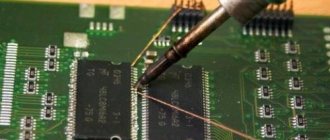
Why is it needed?
Fluctuations in the temperature of the tip of a soldering device can be explained by the following objective reasons:
- instability of the input supply voltage;
- large heat losses when soldering volumetric (massive) parts and conductors;
- significant fluctuations in ambient temperature.
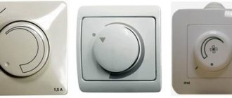
To compensate for the impact of these factors, the industry has mastered the production of a number of devices that have a special dimmer for the soldering iron, ensuring that the temperature of the tip is maintained within specified limits.
However, if you want to save on setting up a home soldering station, the power regulator can easily be made by yourself. This will require knowledge of the basics of electronics and extreme care when studying the instructions below.
Peculiarities
To have a complete understanding of symmetrical thyristors, it is necessary to talk about their strengths and weaknesses. The first include the following factors:
- relatively low cost of devices;
- long service life;
- lack of mechanics (that is, moving contacts that are sources of interference).
The disadvantages of the devices include the following features:
The need for heat removal is approximately at the rate of 1-1.5 W per 1 A, for example, at a current of 15 A, the power dissipation value will be about 10-22 W, which will require an appropriate radiator. For ease of fastening to it for powerful devices, one of the terminals has a thread for a nut.
Triac with radiator mount
- Devices are subject to transients, noise and interference;
- High switching frequencies are not supported.
The last two points require a little clarification. In the case of high switching speed, there is a high probability of spontaneous activation of the device. Interference in the form of a voltage surge can also lead to this result. To protect against interference, it is recommended to bypass the device with an RC circuit.
RC circuit to protect the triac from interference
Operating principle of soldering station controller
There are many known circuits of homemade soldering iron heating regulators that are part of a station used at home.
But they all work on the same principle, which is to control the amount of power delivered to the load. Common options for homemade electronic regulators may differ in the following ways:
- type of electronic circuit;
- an element used to change the power supplied to the load;
- number of adjustment steps and other parameters.
Regardless of the design option, any homemade soldering station controller is a conventional electronic switch that limits or increases the useful power in the heating coil of the load.
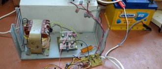
As a result, the main element of the regulator, whether inside or outside the station, is a powerful power supply unit, which provides the ability to vary the temperature of the tip within strictly specified limits.
A sample of a classic soldering iron stand with an adjustable power supply module built into it is shown in the photo.
Making a speed controller
An electric angle grinder is impossible without a speed controller, so that it is possible to reduce the speed.
Using a simple electrical circuit, the device can be easily upgraded by adding the function of changing the speed of rotation.
The regulator circuit from a physics point of view looks like this:
- Resistor – R1;
- Trimmer resistor – VR1;
- Capacitor – C10;
- Triac - DIAC;
- Triac - TRIAC.
The electronic regulator can be not only built-in, but also remote for convenience. In Bosch angle grinders, the electronics set the speed from almost 3 thousand to 11.5 thousand. There is no load on the meter's power, all indicators are taken into account. Reducing the number of revolutions and increasing them is not difficult for the tool. Adjustable rotation speeds are simply necessary when working with an angle grinder.
Converters based on controlled diodes
Each of the possible versions of the devices differs in its circuit and control element. There are circuits of power regulators using thyristors, triacs and other options.
Thyristor devices
In terms of their circuit design, most known control units are manufactured using a thyristor circuit controlled by a voltage specially generated for these purposes.
A two-mode regulator circuit based on a low-power thyristor is shown in the photo.
Using such a device, it is possible to control soldering irons whose power does not exceed 40 watts. Despite its small dimensions and the absence of a ventilation module, the converter practically does not heat up under any permissible operating mode.
Such a device can operate in two modes, one of which corresponds to the standby state. In this situation, the handle of the variable resistor R4 is set to the extreme right position according to the diagram, and the thyristor VS2 is completely closed.
Power is supplied to the soldering iron through a chain with a VD4 diode, on which the voltage is reduced to approximately 110 Volts.
In the second operating mode, the voltage regulator (R4) is moved from the extreme right position; Moreover, in its middle position, thyristor VS2 opens slightly and begins to pass alternating current.
The transition to this state is accompanied by the ignition of the VD6 indicator, which is activated when the output supply voltage is about 150 Volts.
By further rotating the R4 regulator knob, it will be possible to smoothly increase the output power, raising its output level to the maximum value (220 Volts).
Triac converters
Another way to organize the control of a soldering iron involves the use of an electronic circuit built on a triac and also designed for a low-power load.
This circuit works on the principle of reducing the effective voltage value on the semiconductor rectifier, to which the payload (soldering iron) is connected.
The state of the control triac depends on the position of the “switch” of the variable resistor R1, which changes the potential at its control input. When the semiconductor device is completely open, the power supplied to the soldering iron is reduced by approximately half.
The simplest control option
The simplest voltage regulator, which is a “truncated” version of the two circuits discussed above, involves mechanical control of power in the soldering iron.
Such a power regulator is in demand in conditions where long breaks in work are expected and it does not make sense to keep the soldering iron on all the time.
In the open position of the switch, a small amplitude voltage (approximately 110 Volts) is supplied to it, ensuring a low heating temperature of the tip.
To bring the device into working condition, just turn on the S1 toggle switch, after which the soldering iron tip quickly heats up to the required temperature, and you can continue soldering.
Such a thermostat for a soldering iron allows you to reduce the temperature of the tip to a minimum value in the intervals between solderings. This feature slows down oxidative processes in the tip material and significantly extends its service life.
Do-it-yourself speed controller for an angle grinder
The speed controller can be used not only for an angle grinder, but also for a drill, milling machine and commutator motor
The operation of the commutator motor is ensured by any type of electrical voltage. When changing the voltage power, you need to reduce or increase the number of revolutions. The thyristor speed controller helps to change this number.
Regulator assembly steps:
- First, you need to unscrew the handle of the grinder, evaluate the place and figure out where to place the elements of the circuit (if there is no space, then you can make the device in a separate box);
- The resistor can be made of aluminum;
- Provided the triac does not heat up too much, a small radiator is sufficient;
- Next, the structure is soldered.
Finally, it is glued with epoxy resin to secure it. A homemade device can work for years. There are cases when the device accelerates at higher speeds after switching on - this means the stator winding is short-circuited. In this case, a turn short circuit occurred. The stator requires repair, most often it requires rewinding.
What are the typical malfunctions: the winding breaks or burns, a short circuit occurs, the insulating surface breaks through.
Bt136 600E: voltage regulation switching circuit
Manufacturers do not burden cheap angle grinders that do not have sufficient power with voltage control switching circuits, otherwise such angle grinders would no longer be cheap. When starting the grinder, if it is smooth, the process is carried out through an adapter connected by contacts to the rectifier block. The rectifier block converts the current.
The speed regulator will allow you to work for a long time without overloading the tool
But sometimes it makes sense to modernize an angle grinder using an established scheme. The electrical circuit is assembled quite simply. It is not difficult to make, and you can, if desired, connect not only an angle grinder, but any other tool to the finished circuit. However, the tool must have a commutator motor, not an asynchronous one.
A homemade approach to creating a circuit would be as follows:
- To get started, you should download the board if you don’t have it;
- The Bt136 600E triac is used as the power link;
- During operation, the triac will heat up; to avoid this, a heat sink is installed;
- The resistors used provide resistance to current, providing current suppression;
- The regulator is adjusted using a multi-turn trimmer resistor;
- To check, you should connect a light bulb;
- After connecting, the light bulb must be turned off - the triac must be cold;
- Connecting the resulting circuit to the grinder.
If the board is connected correctly, the triac and resistors of the angle grinder should start smoothly, and the use of the rotation speed should be regulated. After this, you can test the grinder in action. Such knowledge may be needed when repairing electric motor faults. For example, when voltage increases or improper balancing occurs.