To transmit electricity over long distances, electric current voltages are increased to hundreds of thousands of volts using power transformers. Since high voltages are very dangerous, the current after the power step-down transformer is used to operate electrical appliances. However, many protective devices are installed along the entire length of the power line. To separate the voltages of the circuits of these devices from the potentials of power lines, a voltage transformer (VT) is used.
This type of instrument is often used as a safe way to connect measuring instruments. The task of the transformer transformer is to convert high-voltage line currents (over 6 kV) to a safe level. The use of such transformers reduces the cost of operating power systems by reducing the cost of insulating equipment operating in low-voltage networks.
Device and principle of operation
Structurally, the VT is not particularly different from other types of converting devices. His device:
- magnetic core laminated from electrical steel plates;
- primary coil;
- one or two secondary windings;
- protective casing (for outdoor structures).
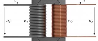
For the appearance and schematic representation of the product, see Fig. 1. The picture shows a device with one (main) secondary winding. Some models have an additional secondary winding, which can be used, for example, to connect measuring instruments.
Rice. 1. Voltage transformer. Structure
Please note that there is no galvanic connection between the terminals of the primary windings and the secondary coils. This is the main difference between instrument transformers and the design of a conventional step-down transformer.
Protective covers are made from different materials. In models used to service high-voltage power lines, dielectrics made of porcelain are used (Fig. 2),
Rice. 2. VT for 110 kV
To cool the windings of such high-voltage units, special transformer oils are used.
In medium-power networks, models with housings based on epoxy resins are used (Fig. 3).
Rice. 3. External type VT
Three-phase voltage transformers with zero leads are made on a magnetic core with five rods. This design protects the windings from overheating, since during single-phase short circuits in the circuits of high-voltage wires, the chain of lines of the total magnetic flux in the transformer itself is closed along the steel core.
The principle of operation also differs little from the operation of a power step-down transformer. The magnetic flux arising in the primary coil propagates along the magnetic circuit, causing an EMF voltage in the secondary winding. The voltage value depends on the ratio of the number of turns in the coils. Since the secondary windings consist of a small number of turns, the output voltage is small (usually it does not exceed 100 V).
The principle of operation of the VT is explained by the diagram in Figure 4.
Rice. 4. Operating principle of voltage transformer
An important task in the manufacture of transformers of this type is to meet the requirements for achieving the required amplitude and angular parameters of the sinusoid, which determine the corresponding accuracy class: 0.5; 1; 3. In reference samples, an accuracy class of 0.2 is used. For measuring instruments, it is important that the accuracy class is as high as possible. The higher it is, the smaller the measurement error of the device.
The accuracy of the parameters of the converted alternating currents depends on the load. The higher the load of the secondary circuit, the greater the error of the voltage transformer (the accuracy class decreases). Optimal voltage parameters at the transformer output are achieved at rated loads. In this mode, the current conversion efficiency increases as it approaches the rated transformation ratio.
The operation of VT is effective at low rated powers in secondary circuits. For these devices, prolonged idling is the norm. Therefore, they are effectively used in line protection systems that are in standby mode most of the time and consume little current.
Device
Transformer type NTMI 6 (10) kV is applicable for changing voltage levels and metering electricity in the network. Used in systems with isolated class neutral. Users ask when purchasing whether grounding is required for the presented structures. The device passport gives a clear answer. Neutral and grounding are required in automatic networks. The transformer connection diagram and unit maintenance are presented by the manufacturer in the instructions.
The transformer container is a metal structure. The lid is equipped with hooks that allow you to transport and install the device in a designated area. The structure has an oil plug at the bottom. The ground bolt is installed here. At the top of the unit there are HV and LV outputs. The hole for topping up the oil cooler is located here and is closed with a plug.
The transformer of category NTMI 10 (6) kV is equipped with a steel core. The coil circuit is copper.
Varieties
According to their design and connection methods, voltage transformers are classified as follows:
- two-winding VT (consists of a primary coil and a main secondary winding);
- three-winding (has two secondary windings. One of them is the main one, and the other is additional);
- grounded (the design of single-phase VTs in which one terminal of the primary winding goes to ground. In models of three-phase VTs, all neutrals are tightly grounded);
- ungrounded;
- type of cascade transformers (the primary winding is formed by cascades of sections);
- a family of capacitive transformers, the design of which contains elements of capacitive dividers;
- models of anti-resonance transformers (see Fig. 5).
Rice.
5. Model of anti-resonance voltage transformer Low-voltage designs that are used in some electronic devices can be distinguished separately. This class of electronic transformers is used in cases where electronic circuits require decoupling that separates high-voltage circuits from low-voltage circuits.
Installation of voltage transformers 6-10 kV
Voltage transformers are designed to power voltage coils of electrical measuring instruments, relays, signaling, control, and automation circuits. In design and principle of operation, they resemble conventional power transformers, differing from them in their low power (for example, the power of the most common transformer NOM-10 is only 720 VA). Voltage transformers are distinguished: by the number of phases - single-phase and three-phase; according to the number of windings - two-winding and three-winding; by accuracy class - 1 and 3 (in networks, substations and switchgear of industrial enterprises) and 0.5 (for electricity metering); by cooling method - with oil cooling and natural air (dry); by type of installation - internal and external. The letters in the designation of voltage transformers mean the following: N - voltage transformer, O - single-phase, M - oil, C - dry, K - filled with compound (in the designation NOS K) or with a compensation winding (in the designation NTMK), I - five-rod, T - three-phase (in the designation STMI). The numbers after the letters indicate the rated voltage of the HV winding. The terminals of the primary winding of HV three-phase transformers are marked with the letters A, B, C, and the secondary LV winding - a, b, c and the number 0. In single-phase transformers, the terminals are respectively designated A - X, a - x. Voltage transformers reduce to 100 V the high voltage required to power devices and secondary circuits and relay protection against ground faults. In switchgears and substations with a voltage of 6-10 kV, voltage transformers NOM-6-10, NTMI-6-10 or NTMK-6-10 are mainly used. Voltage transformers of 6-10 kV of other types in their design, principle of operation and connection to the network are almost no different from those listed. Oil voltage transformer NOM-6 (and NOM-10, similar in design) is shown in Fig. 1. It consists of a tank 4 filled with oil, a magnetic circuit, windings 9 and terminals on the tank cover in the form of bushings 1 and 5.
Rice.
1. Voltage transformer NOM : a - general view, b - removable part;
1.5 - bushings, 2 - grounding bolt, 3 - drain plug, 4 - tank, 6 - core, 7 - screw plug, 8 - high-voltage output contact, 9 - windings Single-phase magnetic circuit, armored type. The windings are layered, wound on a cylinder of electrical cardboard one on top of the other. The HV winding consists of two series-connected coils and has two electrostatic screens for overvoltage protection. The primary and secondary voltage terminals are mounted on the cover, and there is a plug for adding oil. A bolt 2 is attached to tank 4 for grounding the transformer. Tropical voltage transformers additionally have an air-drying filter to remove moisture and industrial contaminants from the air entering them during temperature fluctuations in the oil. The three-phase voltage transformer NTMI-10 is used in 10 kV networks to power various devices and simultaneously monitor insulation. Unlike other voltage transformers, it has three main rods and two additional ones. On the main rods located in the center of the magnetic circuit, there are one primary and two secondary windings - the main and additional; There are no windings on the additional rods; they are used as shunts. The primary and main secondary windings are connected in a star and the zero point is brought out; when installing the transformer, it is grounded. Circuits supplying power to measuring instruments are connected to the main secondary winding, and network insulation monitoring circuits, ground fault relays and alarm devices are connected to the additional winding. The additional winding is designed to monitor insulation in the primary network. When one of the phases of the network is short-circuited to ground, the magnetic flux of the undamaged phases is closed through the outer rods, as a result of which some voltage (about 100 V) will appear at the terminals of the additional winding and current will flow through the windings of the transformer and the voltage relay connected to it, the relay will operate and, closing the contacts alarm circuit will signal a ground fault. Along with oil transformers, voltage transformers with cast insulation made of epoxy resins are manufactured. They do not have the disadvantages of oil-based voltage transformers: they do not require constant supervision and periodic oil changes; have no restrictions for installation in rooms with increased fire hazard and for mobile installations; characterized by less weight and size. As an example, consider a single-phase voltage transformer NOL-11-06 (Fig. with cast insulation, which is an armor-type magnetic circuit, on the middle rod of which there are windings impregnated with an epoxy compound. The ends of the primary winding are connected to the high-voltage terminals in the upper part of the transformer. The ends of the secondary windings windings are connected to contact clamps in the lower part.The magnetic core and windings, filled with epoxy compound, form a solid cast block.
Rice. 8. Voltage transformer NOL-11-06 : 1 - cast block, 2 - high-voltage terminal contact, 3 - secondary winding terminal contacts, 4 - grounding bolt, 5 - brackets
When installing voltage transformers, the following requirements are observed: when installed on two angles, for unobstructed access to the drain valve, the front angle is turned edge down; the oil drain valve and oil level indicator are facing the service corridor; in plugs with breathing holes, remove the gaskets; the insulating distances (in the clear) between the heads of the insulators and the distances between the axes of the phases are maintained according to the design drawings; the distances between transformer casings to ensure normal cooling are maintained at least 100 ml (in the clear); to three-phase transformers NTMK or NTMI, the buses from the HV side are connected so that the yellow phase is connected to the terminal marked A, the green phase to terminal B, the red phase to terminal C (the terminal marked X is grounded); with single-phase NOM transformers, the HV terminal, marked A, is connected to any of the three high-voltage buses (if three single-phase transformers are installed, all terminals marked X are connected by a common bus and grounded); The housings of three-phase and single-phase voltage transformers are connected to the grounding line by separate busbars. The primary and secondary windings of voltage transformers are short-circuited at the terminals and reliably grounded for the entire installation period. The inspection of voltage transformers is carried out similarly to the inspection of current transformers. If the measurement results are unsatisfactory, the windings are dried with a heat blower at an air temperature not exceeding 90 °C or with a current. The voltage supplied to the primary winding is selected so that the short-circuited circuit of the secondary winding flows around a current of 80-85% of the long-term permissible current for the transformer undergoing drying. The current in the secondary winding is monitored with an ammeter. When drying, the terminals of the voltage transformers must be short-circuited and grounded. Voltage transformers are installed in chambers on structures freely without fastenings. They are lifted manually by the casing, and not by the insulators. The secondary winding of voltage transformers is connected to the conductors of secondary circuits only after completion of all installation work before commissioning work and after removal of installation personnel from the switchgear room. This is necessary to ensure that there is no accidental supply of high voltage to the switchgear buses due to reverse transformation.
Issues covered
- What is the structure of voltage transformers NOM-10 and NOL-11-06?
- The rules for installing voltage transformers are considered.
Explanation of markings
To distinguish between types of models, letter markings are used:
- N – voltage transformer;
- T – three-phase model;
- O – single-phase TN;
- C – dry (air cooling);
- M – oil;
- A – anti-resonance models;
- K – cascade devices;
- F – porcelain body type;
- I – five-rod transformer containing a winding for insulation control;
- L – designs in a cast body;
- DE – capacitive;
- G – grounded (the primary coil must be grounded).
Designation
Units of the presented type are designated according to the installed system. Marking allows you to identify the features of the equipment. Operating personnel must see a sign indicating the type of equipment. The decoding of the data is as follows: NTMI-6(10) – UZ (TZ).
- N - voltage transformer.
- T - three-phase.
- M – oil type system cooler, natural circulation.
- And - measuring, an additional winding of the KIZ type is provided.
- 6(10) – parameters of the HV terminal winding, kV.
- UZ (TZ) is a type of climatic placement.
The information is printed on a special plate, which is attached with screws to the transformer housing. The marking must be placed in a visible place.
Technical specifications
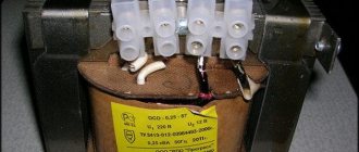
Basic information is indicated on the voltage transformer nameplate.
Rice. 6. Transformer nameplate
Technical parameters of transformers:
- voltage value at the primary phase input;
- voltage at the terminals of the secondary phase windings;
- power factors;
- maximum short circuit voltages.
Important information includes the parameters of the rated frequency and the accuracy class for the rated transformation ratio. On some models, manufacturers indicate angular errors and permissible voltage errors.
Connection diagrams
The simplest connection diagram is used at service points for lines under voltage of 6 - 10 kV. Transformers connected in this way are used to turn on the voltmeter and supply voltage to the relay of the ATS device. An example of such a circuit is shown in Fig. 7.
Rice. 7. Simple voltage transformer connection diagram
Figure 8 shows a circuit used to switch on single-phase transformers to supply safe voltage to loads powered from the secondary windings. This circuit uses a group of single-phase transformers, the coils of which are connected according to the star principle. Please note that the primary windings are connected to a solidly grounded neutral.
Rice. 8. Another example of a connection diagram
This scheme is used in 0.5 – 10 kV networks for connecting measuring instruments and meters. Voltmeters used to monitor insulation are connected using a similar circuit.
The circuit is effective for receiving signals indicating single-phase ground faults. There are other connection schemes, in particular according to the open delta connection type. The peculiarity of such schemes is that the power of a group of two VTs is less than the power of three devices connected in a full triangle circuit not by 1.5 times, but by √3 times.
Some circuits use a combined connection of windings. A delta-star connection is suitable for this purpose. In the operation of such circuits, the rated voltage is 173 V. The specified connection method is used in systems for regulating the excitation of generator and compensator windings.
Transformer connection diagrams
To implement overcurrent protection, various current transformer (CT) connection schemes are used. Which scheme will be used depends on where exactly the CTs are used. For example, in urban networks a “full star” scheme can be used, and in rural networks a “partial star” scheme can be used. In differential and other protections, transformers can be connected in a triangle, and relays can be connected in a star.
Full star
Connection diagram for current transformers “full star” (Fig. 1), in which CTs are installed in all three phases, and the neutral points of the secondary windings are connected in series with one neutral conductor. With this connection, currents flow in the current relay (indicated in the figure as I, II and III) equal to the currents passing through the primary windings of the CT, divided by the transformation ratio nT. In the neutral wire, the geometric sum of all currents In.p. flows, which, if these three currents are equal, is equal to zero.
The circuit coefficient Kcx, which is the ratio of the current in the relay to the current in the phase, is equal to 1, since the current in each of the three relays is equal to the current in the corresponding phase.
Partial star
In Fig. Figure 2 shows the “partial star” circuit. The difference between this scheme and the previous one is that the CTs are installed only in one of the three phases. Otherwise, the circuit is similar: the relay windings (I and III) and the secondary windings of the CT are installed in the same way as in a full star. The geometric sum of the currents of the two phases to which the transformers are connected flows in the neutral wire.
Just like for the previous scheme, the coefficient Ksh = 1.
Triangle
In Fig. Figure 3 shows a diagram for connecting overcurrent protection devices in a delta. With this connection scheme, the secondary windings of the CT are connected in series with opposite terminals, forming a triangle. Thus, a current flows in each of the relays equal to the geometric difference between the current in the corresponding phase and the current in the phase following it:
In this case, Ksh = , since the current in each of the relays is several times greater than the current in the corresponding phase.
"Eight" ("incomplete triangle")
In Fig. Figure 4 shows the CT connection according to the figure-of-eight (incomplete triangle) diagram. In this circuit, the transformers are installed in only two phases, and the secondary windings are connected to each other by opposite terminals. The current in the relay is equal to the difference in the currents of the two phases in which the transformers are installed. With this connection scheme Ksh = 2.
Series and parallel connection of current transformers
Figure 5 shows a diagram of the series connection of current transformers. With this connection of the secondary windings of the CT with the same transformation ratio, the current strength is the same as when only one of the transformers is connected to the circuit, while the load is distributed equally among the two. This scheme can be used when using low-power transformers.
When connecting current transformers according to the diagram shown in Figure 6, the current in the relay is equal to the sum of the currents in the secondary windings of each transformer. Typically, this circuit is used to obtain non-standard transformation ratios.
Application
The main application of primary voltage converters is supplying power to the windings of measuring instruments and connecting protection relays in networks of 380 V and above. Transformers allow you to expand measurement ranges and isolate relays from high phase-to-phase potentials. The inclusion of the terminals of the primary windings between the phase and the ground makes it possible to calibrate the instrument scales taking into account the transformation ratio, which allows you to control the primary parameters of power lines.
Changing the voltage parameters in the primary circuits affects the behavior of variable magnetic fluxes. These disturbances are recorded by the secondary windings, which react by changing the current amplitude and oscillation frequency. Signals are sent to various protective devices, which automatically disconnect sections of lines with short circuits and other critical deviations.
Connection diagram for PKU 3TT 3TN commercial metering point
- Home →
- Articles →
- Connection diagram for PKU 3TT 3TN commercial metering point
Connection diagram for PKU 3TT 3TN commercial metering station is used most often. Let's consider the features of electrical energy metering in networks with voltages of 6 and 10 kV and the applicable connection diagrams for such equipment. Application of voltage and current transformers
Connecting electricity meters directly to high and medium voltage overhead lines is not used, as this would significantly increase the cost of metering devices. To take readings in these cases, groups of step-down voltage transformers (VT) and current transformers (CT) are used. This connection of meters to the network is called indirect. The main problem with this connection method previously was that due to the small value of the measuring current at a reduced load, consumption was not taken into account by inductive type meters. In modern models of electricity meters, this disadvantage is minimized. Instrument transformers are combined, that is, their additional winding is also used for the metering point’s own needs (power supply and heating of its elements, insulation monitoring, for relay (microprocessor) protection and automation). Thanks to the use of step-down transformers and the connection of the meter through a test box, its “hot” replacement (without removing voltage) and maintenance are possible. In parallel with this, instrument transformers protect the electricity meter in case of emergency situations in the network. Connection according to the 3TT 3TN scheme
In this case, anti-resonant instrument transformers are connected to each phase of the network. This connection diagram for PKU 3TT 3TN (commercial metering point) is universal and guarantees accurate metering of electricity consumption under any operating modes of the power grid. The group of modern instrument transformers installed in the PKU is distinguished by its resistance to ferroresonance, as well as the effects of an intermittent arc that occurs in the event of a network phase short circuit. The current and voltage transformers used in the high-voltage module are certified, and their accuracy classes allow them to be used in automatic systems for commercial consumption metering. Other connection schemes
In three-phase networks without a neutral wire, a connection according to the 2TT 3TN scheme can also be used. The meter connections in this case are made using three voltage transformers and two current transformers, connected only to two phases of the network. This connection method is not applicable in networks with a solidly grounded neutral. The connection diagram for PKU 2TT 2TN is the simplest and cheapest to implement, but it is used only with a symmetrical load in the network.
The connection of the PKU meter according to the scheme chosen by the customer is carried out by the manufacturer of the point during its manufacture. As the number of instrument transformers changes, the cost of metering points also varies. So, the difference in the price of a PCU with a 2TT 2TN and 3TT 3TN circuit is about 30 thousand rubles.