What kind of device is this, its designation
A triac is a symmetrical thyristor. In English-speaking countries the name triak is used, and we also have a transliteration of this name - triak. It is not difficult to understand the principle of its operation if you know how a thyristor works. In short, a thyristor only allows current to flow in one direction. And in this way it is similar to a diode, but current flows only when a signal appears at the control terminal. That is, current flows only under certain conditions. Its “supply” stops when the current decreases below a certain value or the circuit breaks (even short-term). Since a triac is essentially a two-way thyristor, when a control signal appears, it passes current in both directions.
In the open state, the triac conducts current in both directions.
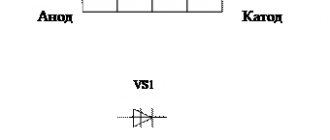
In the diagram it is depicted as two thyristors connected opposite each other with a common control output.
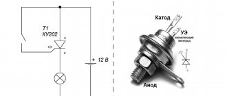
Appearance of the triac and its designation in the diagrams
The triac has three outputs: two power and one control. High voltage current can be passed through the power terminals, and low voltage signals are supplied to the control. Until potential appears at the control terminal, current will not flow in any direction.
General information
A triac (triac) is a type of thyristor and has a large number of pn-type transitions. It is advisable to use it in AC circuits for electronic control. To understand the principle of operation of a triac for dummies in this matter, one should consider its structure, function and scope of application.
Key information
Keys are devices that are used for switching or switching in electrical circuits. There are three types, and each of them has its own advantages and disadvantages. Keys are classified according to switching type:
- Mechanical.
- Electromechanical.
- Electronic.
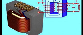
Mechanical keys include switches and switches. They are used in cases where manual switching is necessary to close one or more groups of contacts. The type of electromechanical keys includes relays (contactors). An electromagnetic relay consists of a magnet, which is a coil with a movable core. When power is applied to the coil, it attracts a core with a group of contacts: some contacts close, while others open.
Among the advantages of using electromechanical switches are the following: the absence of voltage drop and power loss on the contacts, as well as the isolation of load and switching circuits. This type of keys also has disadvantages:
- The number of switching operations is limited because the contacts wear out.
- When opened, an electric arc occurs, which leads to the destruction of contacts (electrical erosion). Cannot be used in explosive environments.
- Very slow performance.
Electronic switches come in different bases of semiconductor elements: transistors, controlled diodes (thyristors) and symmetrical controlled diodes (triacs). The simplest electronic switch is a bipolar transistor with a collector, emitter and base, consisting of 2 pn junctions. According to their structure, they are of 2 types: npn and p-np.
Since the transistor consists of 2 pn junctions, depending on the state in which they are located, there are 4 operating modes: main, inverse, saturation and cutoff. In the active mode, the collector junction is open, and in the inverse mode, the emitter junction is open. With two open junctions, the transistor operates in saturation mode. Provided that both transitions are closed, it will operate in cutoff mode.
To use a transistor, only 2 of its states are needed. The cutoff mode occurs in the absence of base current, therefore, the collector current is equal to 0. When a sufficient current value is supplied to the base, the semiconductor device will operate in saturation mode, i.e., in the open state.
If we consider switches on field-effect transistors, then it becomes possible to change its conductivity when the voltage on the gate, which serves as the control electrode, changes. By controlling its operation by influencing the shutter, two states can be obtained: open and closed. Switches based on field-effect transistors are faster than switches based on bipolar transistors.
You might be interested in everything about static electricity
Electronic keys made on thyristors have some special features. A thyristor is a semiconductor radio element with pnpn or npnp junctions and has 3 and sometimes 4 outputs. It consists of a p-layer (cathode), an n-layer (anode) and a control electrode (base). It can be replaced with 2 transistors of different structures. It represents 2 transistor type switches that are connected back to back. The base of one transistor is connected to the collector of the other.
When a gate current is applied to the base, the controlled diode will open and remain in this state until the current value is reduced to zero. When the base current is large, the thyristor is an ordinary semiconductor diode that conducts current in one direction.
It can operate on AC circuits, but only at half power. For these purposes, it is necessary to use a triac.
The principle of operation of a triac
The main difference between a triac and a thyristor is conductivity in two directions at once. The triac can be replaced by 2 thyristors, which have a back-to-back connection in Figure 1. It shows the conventional graphic designation of a triac on electrical circuit diagrams. In some literature you can find other names : triac and symmetrical controlled diode.
Figure 1. Triac (circuit for connecting 2 thyristors) and its graphic designation
There is a simple example that will allow even “dummies” to understand how a triac works. The door in the hotel can be opened in two directions, and 2 people can enter and exit it at once. This simple example shows that a triac can carry current in two directions (forward and reverse) at once, since it consists of 5 pn junctions. Its operation is controlled using the database.
The triac switch layers, made of semiconductor, are similar to the transistor junction, but have 3 additional n-type regions. The fourth layer is located near the cathode and is separated, since the anode and cathode perform certain functions when the current flows, and change places when the current flows in the opposite direction. The fifth layer is located near the base.
When a signal is applied to the control pin, the symmetrical controlled diode will be unlocked, since its anode will have a positive potential. In this case, current will flow through the upper thyristor. When the polarity changes, current will flow through the lower thyristor (Figure 1). This is evidenced by its current-voltage characteristic (volt-ampere characteristic) in Figure 2. It consists of two curves rotated by 180 degrees.
Figure 2. I-V characteristics of the triac
The letter “A” indicates its closed state, and “B” indicates its open state. Urrm and Udrm are permissible values of forward and reverse voltages. Idrm and Irrm - forward and reverse currents.
Types and scope of application
Since a triac is a type of thyristor, their main difference is the parameters of the control electrode (base). In addition, they are classified according to other criteria:
- Design.
- The current value at which an overload occurs.
- Base characteristics.
- Values of forward and reverse currents.
- The magnitude of forward and reverse voltages.
- Type of electrical load. There are power and normal ones.
- Parameter of the current required to open the gate.
- The dv/dt ratio or the speed at which switching occurs.
- Manufacturer.
- Power.
You might be interested in why they install RCDs
Due to the feature of passing current in two directions, they are used in alternating current circuits, since the thyristor cannot operate at full power. Symmetrical thyristors are widely used in the following devices:
- Devices for adjusting the brightness of light or dimmers.
- Speed controllers for various tools (jigsaws, screwdrivers, etc.).
- Electronic temperature control for induction cookers.
- Refrigeration equipment for smooth engine starting.
- Household appliances.
- Industry for lighting, smooth starting of machine drives and mechanisms.
Among the advantages of triacs are their low cost, reliability and they do not generate interference (mechanical type contacts are not used), as well as a long service life. The main disadvantages include the following: the need for additional heat removal, the inability to use at high frequencies, as well as the influence of interference and noise of various kinds.
To suppress interference, you should connect in parallel to the triac, between the cathode and anode, a chain of a capacitor and a resistor with ratings from 0.02 to 0.3 μF and from 45 to 500 Ohms, respectively. For use in any circuit or device, you should know the basic technical characteristics, since knowledge of this information will help avoid many difficulties for a novice radio amateur.
Where is it used and what does it look like?
Most often, a triac is used for switching in alternating current circuits (supplying power to the load). This is convenient, since using a low nominal voltage you can control high-voltage power. In some circuits, a triac is installed instead of a conventional electromechanical relay. The advantage is obvious - there is no physical contact, which makes turning on the power more reliable. The second advantage is the relatively low price. And this is with a significant operating time and high reliability of the circuit.
There are also disadvantages. Devices can become very hot under load, so it is necessary to ensure heat dissipation. Powerful triacs (usually called “power”) are mounted on radiators. Another disadvantage is that the voltage at the output of the triac is sawtooth. That is, only loads that do not place high demands on the quality of the power supply can be connected. If you need a sinusoid, this switching method is not suitable.
You can replace a triac with two thyristors. But you need to select them correctly according to the parameters, and the control circuit will have to be redone - in this version there are two control outputs
It is impossible to distinguish a thyristor and a triac by appearance. Even the markings may be similar - with the letter “K”. But there are also series whose names begin with “TS,” which means “symmetrical thyristor.” If we talk about pinout, this is what distinguishes a thyristor from a triac. A thyristor has an anode, a cathode and a control terminal. For a triac, the names “anode” and “cathode” are not applicable, since the output can be both a cathode and an anode. So they are usually called simply "power terminal" and have a number added to it. The one to the left is the first, the one to the right is the second. The control electrode can be called a gate (from the English word Gate, which refers to this output).
Specifications
Triacs have characteristics that allow them to be used in any circuit. In addition, they also differ in manufacturer - there are domestic and imported. The main difference between imported ones is that there is no need to adjust their operation using additional radio elements, that is, to assemble an additional triac control circuit. Triacs have the following characteristics:
- The value of the maximum reverse and pulse voltage values for which it is designed.
- The minimum and maximum current values at which its transition opens, as well as the value of the maximum pulse current required to open it.
- On and off period.
- dv/dt ratio.
Characteristics are mainly determined by triac labeling using a reference book. The reference information contains information about what it looks like and gives its pinout. When using a triac, the dv/dt characteristic should be taken into account. It shows the coefficient values at which spontaneous switching does not occur due to voltage surges. The reasons for this inclusion may be interference of pulse origin and a voltage drop when switching the switch. In addition, to avoid consequences, an RC circuit should be used, as well as limiting diodes or a varistor. This chain is connected to the emitter and collector of the triac.
You may be interested in this Features of current operation
When choosing a triac, you should pay attention to all the characteristics, since it does not make sense to use a high-voltage type in low-voltage circuits. For example, if the device operates on a voltage of 36 V, then the foreign triac Zo607 with a voltage of 600 V (its analogue is VTA41600V) should not be used.
In addition, in some sources you can find the concept of a snubberless triac. This is the type that is used for inductive loads. Examples of such a model are m10lz47, mac12n and tg35c60.
The principle of operation of a triac
Let's look at how a triac works using the example of a simple circuit in which alternating voltage is supplied to the load through an electronic switch based on this element. Let's imagine a light bulb as a load - it will be more convenient to explain the principle of operation.
Relay circuit on a triac (triac)
In the initial position, the device is in a locked state, no current flows, and the light does not light. When the key SW1 is closed, power is supplied to gate G. The triac goes into the open state, passes current through itself, and the light bulb lights up. Since the circuit operates from an alternating voltage network, the polarity at the triac contacts is constantly changing. Regardless of this, the light bulb is lit, since the device passes current in both directions.
When using an alternating voltage source as power supply, the SW1 switch must be closed all the time as long as the load is required to be in operation. When the contact opens during the next polarity change, the circuit is broken and the light goes out. It will light up again only after the key is closed.
If a DC source is used in the same circuit, the picture will change. After the SW1 key is closed, the triac will open, current will flow, and the light will light up. Then this key can return to the open state. In this case, the power supply circuit of the load (light bulb) is not broken, since the triac remains in the open state. To turn off the power, you must either reduce the current below the hold value (one of the technical characteristics) or briefly break the power circuit.
Using a triac
The triac seems to be such a flexible and universal device that, due to its property of switching to a conducting state, it is triggered by a pulse with a positive or negative sign, which does not depend on the source, exhibiting the property of instantaneous polarity. In fact, the names anode and cathode for the device are not very relevant.
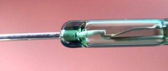
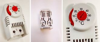
- One of the popular and simplest uses of a triac can be considered its use as a solid-state relay. It is characterized by a low value of inrush current sufficient for loads with high currents. The key function in such a device can be played by a reed switch, or a highly sensitive thermal relay and other contact pairs with a current of up to 50 mA, while the value of the load current can be limited solely by the indicators for which the triac is designed.
- 2No less widespread is the use of a triac as a regulator of lighting intensity and control of the rotation speed of an electric motor. The circuit is based on the use of trigger elements that are installed by an RC phase shifter; an element such as a potentiometer regulates the lighting intensity, and a resistor serves to limit the load current. Pulse generation is performed using a dinistor. After a breakdown in the dinistor, which occurs as a result of a potential difference across the capacitor, the capacitor discharge pulse that occurs instantly turns on the triac.
- Power control in the load using an additional RC circuit in the circuit, which gives a large phase shift, which makes the task of power control easier.
Designation of a triac on the diagram.
Advantages of using triacs
- Increasing the permitted critical value of the switching voltage, which allows the control of large reactive loads without significant failures in switching. This allows you to reduce the number of components, the size of the printed circuit board, reduce the price and eliminate losses due to energy dissipation by the damper.
- Increasing the critical value of change in switching current, which improves the quality of operation at high frequencies for non-sinusoidal voltage.
- Greater sensitivity to high operating temperatures.
- The high value of the permissible voltage reduces the tendency to self-switch on from a state of non-conductivity at high temperatures, which allows their use for resistive loads to control household and heating appliances.
- The durability of the triac, due to operating temperature differences, is characterized by an almost unlimited resource.
- No sparking and the ability to control at the moment of zero current in the network, which reduces electromagnetic interference.
The main advantages of a triac:
- high response frequency for high control accuracy;
- high service life compared to relay electromechanical devices;
- the ability to achieve small device sizes;
- no noise when turning electrical circuits on and off.
Power electronics, using triacs, developed by domestic manufacturers, due to their quality indicators, can provide high competition to Western companies.
Related material: How to connect a capacitor
Types of triacs
Speaking about the types of triacs, one should accept the fact that this triac is one of the types of thyristors. When we mean differences in operation, then a thyristor can be thought of as a kind of triac. The differences concern only the control cathode and the different operating principles of these thyristors. Read what a switching power supply is.
Damaged triacs.
Imported triacs are widely represented on the domestic market. Their main difference from domestic triacs is that they do not require preliminary configuration in the circuit itself, which saves parts and space on the printed circuit board. As a rule, they begin to work immediately after being included in the circuit. You just need to accurately select the required triac according to all the required characteristics.
- BT131-600 is a good replacement for Z00607, only they are the most suitable for all characteristics
- Completely similar to the Z7M is the MAC97A8.
- z3m. Same as just above. Differences in current across the control switch and in maximum voltage. Completely similar to replacing the MAC97A8
- VTA 16 600 - imported, designed for use in circuits up to 16 amperes and voltages up to 600 volts
- This is very often used by Samsung in the production of household appliances. An analogue of this semiconductor and, undoubtedly, better, is BT 134-800. s m2lz47 are not the most reliable in terms of operating conditions in devices with unstable power supply parameters.
- ts122 25. This triac is often called a power thyristor, as it is used in electrical appliances or power tools in soft start mechanisms. A distinctive feature of this unit is its great reliability over a long period of operation.
- 131 6, another name for this VT 131-600, but there is also a simplified name, and many parts have simplified markings. This point is often associated with the fact that using the original or simplified labeling it is not always possible to find exactly the information that is needed.
It will be interesting➡ Marking of SMD transistors
Control circuits
Triac control circuits are simple and reliable. Where, without the use of triacs, a large number of parts were required, and careful adjustment was made according to the parameters, triacs significantly simplified the entire circuit diagram. Including only the main elements in the circuit allows you to miniaturize not only the printed circuit board itself, but also the entire device as a whole. Read the operating principle of the indicator screwdriver.
The dimmer circuit on a triac allows you to create a compact addition to the light switch for smooth adjustment of the lighting level. If necessary, the circuit can be supplemented with components to smoothly change the lighting depending on the brightness of the external background.
The regulator circuit on a triac includes the temperature sensor itself, the power supply network, and the load device. A change in the temperature sensor readings leads to a change in the current readings on the triac switch, which leads to either an increase in voltage or a decrease. Forget about complex mechanical devices with bimetallic plates and burnt-out contacts. Engine speed control circuits are fundamentally no different in construction principle from other similar ones. The nuances concern only the parameters of current and voltage to the motor.
Triac on an electronic circuit.
Controlling a triac through an optocoupler allows you to connect electrical equipment that needs to be controlled. Directly to the computer via the LPT port. The optocoupler in this example allows you to directly protect the computer motherboard from overload and failure. A kind of smart fuse with control function. Controlling a triac from a microcontroller allows you to achieve very accurate current and voltage indicators, at which the triac itself and the distribution of supply voltage to various load devices are controlled.
Control signals
The triac is controlled not by voltage, but by current. To open the gate, a certain level of current must be supplied. The characteristics indicate the minimum opening current - this is the required value. Usually the opening current is very small. For example, to switch a 25 A load, a control signal of about 2.5 mA is supplied. Moreover, the higher the voltage applied to the gate, the faster the junction opens.
Voltage supply circuit for controlling a triac
To switch the triac to the open state, voltage must be applied between the gate and the conventional cathode. Conditional, because at different times, the cathode is one power output, then another.
The polarity of the control voltage, as a rule, must be either negative or must coincide with the polarity of the voltage at the conventional anode. Therefore, a method of controlling a triac is often used in which a signal is supplied to the control electrode from a conditional anode through a current-limiting resistor and a switch. It is often convenient to control a triac by setting a certain current strength of the control electrode, sufficient for unlocking. Some types of triacs (called four-quadrant triacs) can be triggered by a signal of any polarity, although this may require more control current (namely, more control current is required in the fourth quadrant, that is, when the voltage at the conventional anode has a negative polarity, and at the control electrode - positive).
Description of the operating principle and device
The main difference between these elements and thyristors is the bidirectional conductivity of electric current. Essentially, these are two SCRs with common control, connected back-to-back (see A in Fig. 1).
Rice. 1. Circuit with two thyristors, as an equivalent of a triac, and its conventional graphic designation
This gave the name to the semiconductor device, as a derivative of the phrase “symmetrical thyristors” and was reflected in its UGO. Let us pay attention to the designations of the terminals, since current can be carried in both directions, the designation of the power terminals as Anode and Cathode does not make sense, therefore they are usually designated as “T1” and “T2” (options TE1 and TE2 or A1 and A2 are possible). The control electrode is usually designated “G” (from the English gate).
Now consider the structure of the semiconductor (see Fig. 2.) As can be seen from the diagram, there are five junctions in the device, which allows you to organize two structures: p1-n2-p2-n3 and p2-n2-p1-n1, which, in fact, are two counter-current thyristors connected in parallel.
Rice. 2. Block diagram of a triac
When negative polarity is formed at the power terminal T1, the trinistor effect begins to manifest itself in p2-n2-p1-n1, and when it changes, p1-n2-p2-n3.
Concluding the section on the principle of operation, we present the current-voltage characteristics and the main characteristics of the device.
I-V characteristics of the triac
Designation:
- A – closed state.
- B – open state.
- UDRM (UPR) – maximum permissible voltage level for direct connection.
- URRM (UOB) – maximum reverse voltage level.
- IDRM (IPR) – permissible direct current level
- IRRM (IOB) - permissible level of reverse switching current.
- IN (IUD) – holding current values.
How to check a triac
The habit of checking all elements before soldering comes with age. You can check the triac using a multimeter and a small test circuit with a battery and a light bulb. In any case, you must first figure out how the pins are located on your device. This can be done according to the pinout of each specific series. To do this, we enter the markings that are on the case into the search engine. In some cases, you can add a "pinout". If there are Russian-language descriptions, it will be somewhat easier. If there is no information in Russian, you will have to search on the Internet. Replace the word “pinout” with the word “datasheet”. Sometimes you can enter “datasheet” in Russian letters. Translated, this is “technical specification”. From the tables and figures in the description, it is easy to understand where the power outputs are located (T1 and T2), and where the gate (G) is located.
Example of pinout. Everything can be understood without knowing the language
With a multimeter
Testing a triac with a multimeter is based on the principle of its operation. We take a regular multimeter and put it in the dialing position. The power outputs must communicate with each other in both directions. We touch the probes to the outputs T1 and T2. Numbers should appear on the screen. This is the transition resistance. If you swap the probes, the resistance may change, but there should be no break or short.
Check with a multimeter
But between the gate and the power outputs there must be a “break” (infinitely large resistance). That is, they should not “ring” regardless of the location of the probes. By checking the resistance between different terminals, you can determine the functionality of the triac.
With light bulb and battery
To test a triac without a multimeter, you will have to assemble a simple test circuit powered by a nine-volt Krona battery. You will need three wires about 20 cm long. The wires are preferably flexible, multi-core. It's easier if they are different colors. Red, blue and any other are best. Let it be yellow. We cut the blue one in half, solder a 9 V incandescent light bulb (or look at the voltage your battery produces). One piece of wire for the thread, the other for the central terminal from the bottom of the base. To make it more convenient to work, it is better to solder “crocodiles” - spring clips - onto each wire.
How to test a triac without a multimeter
Let's put together a diagram. We connect the wires in this order:
- Red one end is on the plus crown, the other is on the T1 terminal.
- Blue - for minus crowns and T2.
- We connect the yellow wire with one edge to gate G.
After the circuit has been assembled, the light should not light up. If it lights up, the triac is broken. If it doesn't light up, check further. Briefly touch T2 with the free end of the yellow wire. The light should light up. This means that the symmetrical thyristor has opened. To close it, you need to touch the T1 output with the wire. If everything works, the device is working properly.
Symmetrical thyristor
If you analyze the development path of semiconductor electronics, it almost immediately becomes clear that all semiconductor devices are created on junctions or layers (np, pn).
The simplest semiconductor diode has one junction (pn) and two layers.
A bipolar transistor has two junctions and three layers (npn, pnp). What happens if you add another layer?
Then we will get a four-layer semiconductor device called a thyristor. Two thyristors connected back-to-back are a triac, that is, a symmetrical thyristor.
In English technical literature you can find the name TRIAC ( triode for alternating current).
This is how a triac is depicted on circuit diagrams.
The triac has three electrodes (terminals). One of them is the manager. It is designated by the letter G (from the English word gate - “shutter”). The other two are power electrodes (T1 and T2). On diagrams they can also be designated by the letter A (A1 and A2).
How to avoid false positives
Since a small potential is enough to trigger a triac, false alarms are possible. In some cases, they are not terrible, but they can also lead to damage. Therefore, it is better to take action in advance. There are several ways to reduce the likelihood of false inclusions:
- Reduce the length of the line to the gate, connect the control circuit - gate and T1 - directly. If this is not possible, use shielded cable or twisted pair.
- Reduce shutter sensitivity. To do this, place a resistance in parallel (up to 1 kOhm).
In almost all circuits with triacs, there is a resistor in the gate circuit that reduces the sensitivity of the device
- Use triacs with high noise immunity. They have the letter “N” added to their labeling, for “insensitive”. They are called “H-series triacs”. They differ in that the minimum transition current is much higher. For example, a BT139-600H triac has a transition current IGT min =10mA.
As already said, the triac is controlled by current. This makes it possible to connect it directly to the outputs of the microcircuits. There is one limitation - the current should not exceed the maximum permissible. Typically this is 25 mA.
Installation features
Just like thyristors, triacs heat up during operation, so during assembly it is necessary to ensure heat dissipation. If the load is low-power or the power supply is pulsed (short-term connection for a period of less than 1 second), installation without a radiator is allowed. In other cases, it is necessary to ensure good contact with the cooling device.
There are three ways to fix a triac to a radiator: riveting, screwing, and clamping. The first option for self-installation is not recommended, as there is a high probability of damage to the housing. The easiest way to install it at home is with a screw.
Triac installation procedure
Before installation begins, inspect the body of the device and the radiator (cooler) for scratches and chips. They shouldn't exist. Then the surface is wiped from dirt with a clean rag, degreased, and thermal paste is applied. Then insert it into the threaded hole in the radiator and clamp the washer. The torque should be 0.55Nm-0.8Nm. That is, it is necessary to ensure proper contact, but you also cannot overtighten, as there is a risk of damaging the case.
Power regulator circuit for inductive load on a triac
Please note that the triac is installed before soldering. This reduces the mechanical load on the device taps. And one more thing: when installing, make sure that the housing is pressed tightly against the cooler.
