A thyristor is a semiconductor device with a pnpn structure that plays the role of a switch in circuits with high currents, while it is controlled by a low-current signal. It is used to switch on power electric drives and generator excitation systems. Switched currents reach up to 10 kA.
The peculiarity of thyristors is that when a control signal is applied, they open and remain in this state, even if the signal is subsequently removed. The only requirement is that the current flowing through them must exceed a certain value, which is called the holding current.
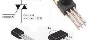
Some thyristors only allow current to flow in one direction. These are dinistors that are triggered when a significant voltage is exceeded. There are also SCRs controlled by supplying current to the third terminal of the device.
Thyristors that pass current in both directions are called triacs or triacs. In addition, there are photothyristors controlled by light.
Main characteristics
To check the SCR, you need to know and understand what is hidden behind the main parameters and why they need to be measured.
The control unlocking voltage Uy is a constant potential on the control electrode, causing the thyristor to open.
Urev max is the maximum reverse voltage at which the thyristor is still in working condition.
Ioc cp is the average value of the current flowing through the thyristor in the forward direction while maintaining its operability.
Types of thyristors and their special properties
Semiconductor technologies are still being developed and improved. Over several decades, new types of thyristors have appeared, which have some differences.
- Dinistors or diode thyristors. They differ in that they have only two outputs. They are opened by applying high voltage to the anode and cathode in the form of a pulse. They are also called “uncontrolled thyristors”.
- SCRs or triode thyristors. They have a control electrode, but the control pulse can be applied to: The control output and the cathode. Name - with cathode control.
- To the control electrode and anode. Accordingly, control of the anode.
Thyristors can be controlled from both the anode and cathode
There are also different types of thyristors according to the locking method. In one case, it is sufficient to reduce the anode current below the holding current level. In another case, a blocking voltage is applied to the control electrode.
By conductivity
We said that thyristors conduct current only in one direction. There is no reverse conduction. Such elements are called reverse-non-conducting, but there are not only such elements. There are other options:
- They have a low reverse voltage and are called reverse-conducting.
- With non-standardized reverse conductivity. They are installed in circuits where reverse voltage cannot occur.
- Triacs. Symmetrical thyristors. Conduct current in both directions.
They are distinguished mainly by the type of conductivity and control method
Thyristors can operate in switch mode. That is, when a control pulse arrives, supply current to the load. The load, in this case, is calculated based on the open voltage. The maximum power dissipation must also be taken into account. In this case, it is better to choose metal models in the form of a “flying saucer”. It is convenient to attach a radiator to them for faster cooling.
Classification by special operating modes
The following subtypes of thyristors can also be distinguished:
- Lockable and non-lockable. The operating principle of an unlockable thyristor is slightly different. It is in the open state when the plus is applied to the anode, the minus is on the cathode. It goes into a closed state when the polarity changes.
- Fast-acting. They have a short transition time from one state to another.
- Pulse. It transitions very quickly from one state to another, and is used in circuits with pulsed operating modes.
The main purpose is to turn on and off a powerful load using low-power control signals
The main area of use of thyristors is as an electronic key used to close and open an electrical circuit. In general, many common devices are built on thyristors. For example, a garland with running lights, rectifiers, pulsed current sources, rectifiers and many others.
Determination of control voltage
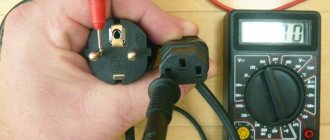
Now you can start testing the SCR. To do this, let's take KU202N with an operating current of 10 A and a voltage of 400 V.
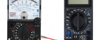
Most radio amateurs have a multimeter and the question inevitably arises of how to check a thyristor with a multimeter, whether this is possible and what additional things may be needed. The sequence of actions is as follows:
First, switch the multimeter to the resistance measurement position with a range of 2 kOhm. In this mode, the voltage of the tester's internal power supply will be present on the test leads;- We connect the probes to the anode and cathode of the SCR. The multimeter should show a resistance close to infinity;
- We connect the anode and the control electrode with a jumper. The resistance should drop, the SCR has opened;
- We remove the jumper, the device again shows infinity. This is due to the holding current being too low.
Since the thyristor is controlled by both negative and positive signals, it can be opened by connecting the control electrode to the cathode with a jumper.
The multimeter should be in ohmmeter mode and the probes connected to the anode and cathode. This way you can determine what voltage the thyristor is controlled by.
Testing using the light bulb and battery method
For this method, it is enough to have on hand only a light bulb, a battery, 3 wires and a soldering iron to solder the wires to the electrodes. This set can be found in everyone's home.
Read also: What is the best miter saw for wood?
When testing a device using the battery and light bulb method, you need to estimate the one hundred mA current load that the light bulb creates on the internal circuit. The load should be applied briefly. When using this method, a short circuit rarely occurs, but to be one hundred percent sure that it definitely won’t happen, it is enough to pass current through all pairs of thyristor electrodes in both directions.
The light bulb and battery test is carried out according to three schemes:
- In the first circuit, a positive potential is not supplied to the control electrode, so no current flows and the light bulb does not light up. If the light is on, the thyristor is not working properly.
- In the second circuit, the thyristor is brought into a state of high conductivity. To do this, you need to apply a positive potential to the control electrode (CE). In this case, if the light does not light, then something is wrong with the thyristor.
- In the third circuit with UE, the power is turned off, the current in this case passes through the anode and cathode. Current flows due to confinement of the internal junction. But in this case, the light bulb may not light up not only due to a malfunction of the thyristor, but also due to the flow of a current of less value through the circuit than the extreme holding value.
So the serviceability of the thyristor can be easily checked at home, without having special equipment on hand. If the circuit is broken through the anode or cathode, the thyristor is activated into a low conductivity state.
When using this method, a short circuit rarely occurs, but to be one hundred percent sure that it definitely won’t happen, it is enough to pass current through all pairs of thyristor electrodes in both directions
Functionality check
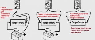
The second testing option is as follows. A lamp at the same voltage is connected to the DC power supply through a thyristor.
A multimeter is connected to the anode and cathode in DC voltage measurement mode. The measurement range must be greater than the source voltage.
Then, control voltage is supplied to the control electrode using a battery of any rating and a pair of wires. The thyristor should open and the light should light up.
The tester first shows the voltage of the power source, after exposure to a small value, which corresponds to the potential drop across the thyristor in the open state.
After this, you can remove the control action, the lamp will continue to burn, since the current flowing through the device is greater than the holding current.
How to check thyristor KU202N
Well, finally we move on to the most important thing - checking the thyristor. We will check the most popular and famous Soviet thyristor - KU202N.
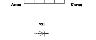
And here is his pinout
To test the thyristor, we need a light bulb, three wires and a DC power supply. On the power supply we set the voltage for the light bulb to light up. We tie and solder wires to each thyristor terminal.
We supply “plus” from the power supply to the anode, and “minus” to the cathode through a light bulb.
Now we need to apply voltage relative to the anode to the Control Electrode (CE). For this type of thyristor, Uy is the unlocking constant control voltage of more than 0.2 Volts. We take a one and a half volt battery and apply voltage to the UE. Voila! The light bulb came on!
You can also use multimeter probes in continuity mode; the voltage on the probes is also more than 0.2 Volts
We remove the battery or probes, the light should continue to light.
We opened the thyristor by applying a voltage pulse to the UE. Everything is elementary and simple! In order for the thyristor to close again, we need to either break the circuit, that is, turn off the light bulb or remove the probes, or apply reverse voltage for a moment.
Checking the dinistor
To determine the performance of the dinistor, a power source with a voltage higher than the turn-on voltage of the dinistor may be required.
To limit the current you will need a 100-1000 Ohm resistor. Now you can connect the plus of the source to the anode, and the cathode to one of the terminals of the limiting resistor.
The second end of the resistance is connected to the minus of the power source . Before this, you need to connect a multimeter in DC voltage measurement mode to the anode and cathode.
The tester values should be within millivolts. The dinistor opened.
Characteristics
All its parameters can be divided into two types: limiting and electrical. Let's look at them in more detail. Please note that the device cannot operate at the limit values indicated below for a long time; these are peak values that it will withstand in a very short period.
The electrical parameters of ku202n characterize the operation of the thyristor under operating conditions. Below are their meanings:
Unusual way
There is another option for checking the thyristor with a multimeter, without ringing. But in this case, the device must be low-power, with a low holding current.
The transistor test connector is used for testing. It is usually located below the switch and is a round connector approximately 1 cm in diameter.
It should have the following designations: B - means the base of the transistor, C - collector, E - emitter.
If the thyristor opens with a positive voltage, then the control terminal must be connected to the base, the anode and cathode to the collector and emitter, respectively.
Since the tester measures the gain when testing a transistor, even in this case it will give some values that will be incorrect. But this is not important, the main thing is to make sure that the thyristor is working properly.
Application of thyristor
The purpose of thyristors can be very different, for example, a homemade welding inverter using thyristors, a charger for a car (thyristor in the power supply) and even a generator are very popular. Due to the fact that the device itself can pass both low-frequency and high-frequency loads, it can also be used for a transformer for welding machines (their bridge uses exactly these parts). To control the operation of the part in this case, a voltage regulator on the thyristor is needed.
Photo - using Thyristor instead of LATR
Don't forget about the ignition thyristor for motorcycles.
Check in the circuit
Sometimes it is necessary to check a thyristor without removing it from the circuit. To do this, the control electrode must be disconnected. After this, a multimeter is connected to the anode and cathode in DC voltage measurement mode.
The second tester is connected to the anode and control electrode of the thyristor. The second device must be in ohmmeter mode.
If the test leads are connected correctly, the readings of the first tester will be within a few tens of millivolts.
If not, then the probes need to be swapped and everything repeated. Before measurements, you need to make sure that the board and the entire device are de-energized.
Classification of thyristors
By conductivity and number of pins:
- diode thyristor (additional name “dinistor”) - a thyristor that has two terminals: a diode thyristor, not conducting in the opposite direction;
- diode thyristor, conducting in the opposite direction;
- diode symmetrical thyristor (eng. en:DIAC);
- triode thyristor, not conducting in the opposite direction (additional name “thyristor”);
Previously, thyristors in the domestic literature were called “controlled diodes”.
The difference between a dinistor and a trinistor
There are no fundamental differences between a dinistor and a trinistor, however, if the opening of a dinistor occurs when a certain voltage is reached between the anode and cathode terminals, depending on the type of a given dinistor, then in a trinistor the opening voltage can be specially reduced by applying a current pulse of a certain duration and magnitude to its control electrode with a positive potential difference between the anode and cathode, and the trinistor design differs only in the presence of a control electrode. SCRs are the most common devices from the “thyristor” family.
The difference between a triode thyristor and a turn-off thyristor
Switching to the closed state of conventional thyristors is carried out either by reducing the current through the thyristor to the value Ih
, or by changing the voltage polarity between the cathode and anode.
Switchable thyristors, unlike conventional thyristors, under the influence of the control electrode current can transition from a closed state to an open state, and vice versa. To close a turn-off thyristor, it is necessary to pass a current of opposite polarity through the control electrode than the polarity that caused it to open.
Triac
Main article: Triac
A triac (symmetrical thyristor) is a semiconductor device, in its structure it is analogous to the back-to-back connection of two thyristors. Capable of passing electric current in both directions.