Types of designs
Using incorrectly connected electrical appliances can be unsafe. The danger is that during use a breakdown may occur, as a result of which the voltage will transfer to the device body. This voltage can either damage the device itself or cause electrical injury of varying severity to a person (including death). To prevent such problems, two types of grounding can be used :
- Natural. This includes massive structures that are permanently in the ground. The role of natural grounding conductors is given to the foundations of buildings, water pipes, metal structures and sheet piles, well fixed in the ground. The advantage of such structures is that providing grounding with their help does not require additional costs. However, natural loop resistance cannot be calculated.
- Artificial. Grounding of this kind is created specifically from horizontal and vertical elements (electrodes) made of a certain material and having a specific size. The main elements of the artificial contour are most often steel parts that have a round or angular shape. The quality of such grounding depends on the resistance possessed by artificial ground electrodes. The resistance of each electrode is determined using a special formula.
All modern devices powered by electricity are grounded. All that needs to be done is simply to provide a connection to the main grounding system.
Which grounding device is more effective: natural or artificial?
All news
02.03.16 ,
There are two types of grounding: artificial and natural. The role of natural grounding is performed by parts of the metal structures of the object that are constantly located in the ground: foundation reinforcement, water supply, casing pipes, etc. Artificial grounding is a separate independent structure mounted in the ground. Almost every contractor is faced with the question when installing grounding, which grounding is better: artificial or natural?
To answer this question, let us turn to regulatory documents, namely paragraphs 1.7.54 and 1.7.109 of the “Rules for the Construction of Electrical Installations” (PUE). Here we see the answer: both natural and artificial grounding electrodes are suitable for grounding. Let's find out in what cases it is more correct to use one method or another? Let's look at each option in more detail.
Option 1. Natural grounding
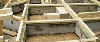
If you decide to use a natural grounding system, then you need to know about many factors: the type of foundation of the object, its material, as well as the aggressiveness of the soil. Section PUE 1.7.109 outlines design options for the facility that can be used as a grounding conductor. The most common of these is the foundation. There are several types of foundations: strip, columnar, pile and slab. The choice of base depends on soil density, seismic activity, surface topography, groundwater level and soil freezing depth. The materials used are: reinforcement, concrete, brick, wood, rubble, asbestos-cement or metal pipes. Detailed information about the foundation can be found in the regulatory documentation (SNB 5.01.01-99 Foundations and foundations of buildings and structures). Thus, when deciding to use your foundation as a ground electrode, you need to make sure that it has electrically connected metal parts.
All elements of the natural grounding system must be combined into a common circuit and in contact with the ground to drain currents directly or through concrete. Also, the selected ground electrode must meet the requirements of the PUE regarding the cross-sectional area of the conductor (Table 1.7.4). During the operation of a natural ground electrode, destruction of its structure or disruption of the operation of devices associated with it must not be allowed.
Sewage and central heating pipes, as well as pipelines for flammable and explosive mixtures, are not allowed as a grounding conductor. Pipes easily corrode the metal, breaking the electrical contact. This type of grounding is certainly more economical: it does not require costs for materials, installation and dismantling of the grounding device, but during its long-term operation, repairing damaged areas will cost no less than installing a separate grounding.
Natural grounding
Option 2. Artificial ground electrode
It is a set of electrodes installed in the ground and connected to electrical equipment using a grounding conductor. Copper-plated steel, galvanized steel or ferrous metals are used as electrode materials:
- Copper-bonded steel has the highest electrical conductivity and adhesion to various materials. The bond between copper and steel is stronger than with zinc, which is why copper-plated rods are stronger than galvanized rods. Copper is less electrochemically active than zinc and steel, which increases service life up to 100 years.
- Galvanized steel is a corrosion-resistant material with low resistivity. Electrodes made of this metal are highly resistant to acidic environments with an average service life of 30 years.
- Ferrous metals have high mechanical strength, but quickly break down when used in an aggressive soil environment, forming rust and corrosion. And, as a result, we get a high current flow resistance, which poses a danger to human life.
The dimensions of the conductors must comply with the requirements of GOST R 50571.5.54-2013. Many options for installing a grounding device help to ensure the required contact area of the surface of the ground electrode with the ground, which in turn allows you to influence the value of the resistance to current spreading. The advantage of an artificial ground electrode is that it can be installed deep into the ground, where the resistivity is lower due to groundwater that flows down. This ensures the stability of the final resistance.
Artificial ground electrode
Let's summarize: you can choose any of the options described above as a grounding conductor, the main thing is to approach this issue responsibly.
For the safety of your home and long service life, choose a grounding device with a corrosion-resistant coating manufactured in accordance with regulatory guidelines. Call or write to our Technical Center and we will select the necessary grounding kit for your facility. See also :
- Grounding in a private house
- What can be used as a natural grounding agent?
- Lightning protection for a private home and bathhouse
[News block code for embedding on your website] [RSS feed for subscribing to news]
Do you want to receive selected news about lightning protection and grounding once every 3-4 weeks? Register and automatically receive an email newsletter with a selection.
All news is published in our groups in instant messengers and on social networks. [News channel on Telegram]
Elements of artificial contour
Despite the fact that natural and artificial grounding conductors perform the same function, which is to protect against electric shock, the use of the former is not always advisable. Installation of an artificial structure is necessary when:
- It is the only one possible.
- The natural circuit cannot withstand current loads.
In both cases, the optimal solution is to create an artificial grounding system with preliminary calculations. In the process of such calculations, the shape, size of the circuit and the material from which the electrodes will be made are determined. The base for them is usually steel, which has a coating:
- Made from zinc. Provides resistance to corrosion and acidic environments. Parts made from this material have low resistance.
- Made of copper. Steel and copper are characterized by good adhesion, so such electrodes are highly durable and have good contact with other materials. They have excellent electrical conductivity and long service life, ensured by the low electrochemical activity of metals.
Another option for manufacturing electrodes (from ferrous metals) has a significant drawback, expressed in low resistance to corrosion and rust. Due to the high strength, the resistance to current flow increases, resulting in a very dangerous situation for humans.
Resistance of artificial ground electrode
In order for the charger to effectively perform its task, it must have a spreading resistance that does not exceed certain values. This parameter shows how well the device conducts electric current.
For a grounded electrical installation with a voltage of 380V, the resistance of the artificial ground electrode should not exceed 30 Ohms. Operating under high voltage, medical equipment, server units, video surveillance systems are grounded with a resistance of 0.5-1 Ohm.
Calculation for artificial grounding conductors is carried out in order to determine how many vertical and horizontal conductive rods should be installed to obtain optimal resistance.
Electrode placement
The parts included in the general grounding structure can be located vertically or horizontally.
In the first installation method, the electrodes are buried 70 cm into the ground. However, their length should not exceed 5 m, and their diameter should be in the range of 10-16 mm. The horizontal laying method involves deepening the grounding bars by 50 cm (in the case of arable land by 1 m). Horizontally located steel rods with a diameter of more than 1 cm (or steel strips with a thickness of more than 4 mm) are used to connect vertically installed elements, the joints between them are fixed by welding. This method shows its effectiveness only if there is sufficient electrical conductivity of the top layer of soil.
Electrical installation rules require grounding for electrical equipment for domestic and industrial purposes. There are no clear requirements regarding how the electrodes should be located in the ground. In each specific case this is determined individually.
Electrical safety created with the help of artificial grounding conductors is realized by reducing the potential difference and removing stray current. Leakage current occurs due to the interaction of the grounding element and the phase cable. At the same time, uninterrupted and efficient functioning of electrical equipment is ensured.
What is the difference between vertical and horizontal grounding conductors?
There is no particular functional difference between these types of electrodes. When installing both vertical and horizontal elements, only the depth of their immersion is important.
Standard depth indicators:
- The upper end of the grounding elements laid vertically in the ground is deepened by 0.7 m. They are laid horizontally on the bottom, along the perimeter of the foundation. The diameter of the electrodes is from ten to sixteen mm, the length is up to 5 m.
- The horizontal elements of the grounding device go 0.5 m into the ground. If the land is arable, they must be laid to a depth of at least 1 m. The rationality of their use is justified only if the top layer of soil has good electrical conductivity. This type of electrodes can be used to connect vertical grounding elements. Connections are made by welding. Either rounded steel with a diameter of more than 10 mm or steel strips with a thickness of more than 4 mm are used.
Note! It is more practical to use vertical grounding conductors. Horizontal grounding elements are extremely difficult to bury into the soil to the required depth. At shallow depths in such grounding conductors, the main characterizing indicator begins to deteriorate - the resistivity increases.
There is no specific profile requirement that regulates the installation of grounding conductors strictly in a vertical position (only advisory in nature). It is possible to install a vertical electrode at a slight angle. This factor does not affect the functionality of the ground electrode.
Installation Features
In order for an artificial grounding structure to effectively perform a protective function, it must be correctly installed using technology and special equipment.
When laying two horizontal electrodes from the grounded part of the installation, they must be positioned in the opposite direction. If the number of grounding conductors is more than two, they must be installed at an angle of 90−120 degrees. In this way, it will be possible to achieve an improved resistance index of the parts. During the installation process, electrical potentials are distributed. The presence of a significant difference in indicators on the surface of the earth and inside it will lead to the emergence of dangerous voltages. In order to prevent such a situation and equalize the parameters, an artificial grounding element in the form of a grid is used, when horizontal electrodes are located lengthwise and crosswise, and the places of their intersections are fixed by welding.
With this installation method, it is necessary to avoid placing the electrodes too close to each other. Otherwise, shielding will occur, which will significantly reduce the efficiency of the ground electrodes.
Artificial type grounding conductors must have a natural color ; they cannot be painted, as this will lead to the formation of an insulating layer. It will limit the flow of electricity into the ground. It is allowed to coat with bitumen paint only the connection points of conductors treated by welding. This coating will protect the elements from early destruction.
The simplest and most effective (from the point of view of installation and operation) is the installation of a round grounding structure. It has a low cost because its production requires a minimum amount of materials. The corrosion resistance of a round contour is much higher than that of other shapes.
Resistance measurement
The final stage of installation of the structure is to measure the resistance of the electrodes.
This parameter is the main qualitative characteristic of the operation of an artificial type grounding loop. It depends on factors such as the area of the electrodes and the electrical resistivity of the soil. Resistivity shows the level of electrical conductivity of the soil, acting as a conductor. It varies in different soils; its value is influenced by humidity, temperature, composition and density of the soil, as well as the presence of salts, acidic and alkaline residues in it.
The resistance of the installed circuit is checked using special equipment. If the system contains branches, then first take measurements on individual sections of the main line and compare them with the indicators on the section connected to the ground electrode. After this, readings are taken between grounded electrical installations and correlated with the readings in previously checked areas.
Types of ground electrodes
If the conductivity of the latter is low, the design of the ground electrode has to be complicated.
There are still difficulties: the soil environment has a corrosive effect on the electrodes, in some cases the metal is “washed out” as a result of electrolysis.
All this encourages the development of a variety of designs of grounding conductors.
Natural and artificial grounding conductors
Natural grounding systems are structures in which the discharge of electricity into the ground is not the main function. For example:
- Foundations constructed from reinforced concrete.
- Underground utility networks: pipelines, casing and armor of cables.
- Railway rails and other ground communications.
The use of reinforced concrete foundations as grounding conductors is permitted under the following conditions:
- Soil moisture - at least 3%. In dry soil, concrete has high resistance.
- There is no waterproofing (bitumen coating is allowed).
- Monolithic design. You can also use prefabricated ones, but for this it is necessary to connect the fittings of adjacent blocks by electric welding. The same is done with a pile foundation: the pile reinforcement is welded to the grillage reinforcement.
Grounding switch ZR 10/630 UHL3
The use of natural grounding conductors can significantly reduce the cost of the grounding device.
If this is not possible, artificial grounding devices are used - special designs aimed only at ensuring electrical contact with high conductivity between the grounded element and the ground.
An artificial grounding system consisting of several interconnected electrodes is called complex. If it is mounted around an object, then the name “ground loop” is used.
Electrodes are mainly made of steel:
- black (low carbon – St.0, St.3, etc.);
- stainless;
- black coated with copper, aluminum or zinc.
Electrodes made of “black” steel are made larger in order to resist corrosion, but they are still cheaper than stainless steel or coated ones. However, they have an important drawback: when rust appears on the surface layer, its resistance increases.
Horizontal, vertical grounding conductors
If the conductivity of the surface soil layer is high and there is enough free space, the artificial grounding electrodes are laid horizontally in shallow trenches. On arable lands, the laying depth is 1 m, on others - 0.5 m.
The advantage of the method: minimal amount of manual labor.
On rocky and permafrost soils, horizontal backfilling is the only possible option. If the conductivity of the surface layer of soil is low, which happens quite often, an electrolytic grounding conductor is used. This is an L-shaped pipe with holes in the wall, filled with mineral salt.
When salts dissolve in ground moisture, an electrolyte is formed, which gives a double effect:
- soil conductivity increases;
- the freezing temperature decreases (frozen soil has high resistance).
During the dry period, water is poured into the ground electrode through the short part brought out. Substances are added to salt to inhibit their leaching in the spring.
The backfill is periodically updated.
In the vast majority of cases, surface soil has a number of disadvantages:
- weak conductivity - due to low density and humidity;
- uneven spreading of current - due to low and unstable distributed density;
- significant air content, which promotes corrosion;
- temperature changes;
- freezing.
Dense and moist deep layers do not have these disadvantages, which is why electrodes are more often placed vertically. The term “vertical” is conditional: conductors can be located at an angle of up to 45 degrees.
Types of vertical grounding electrodes
The following types of vertical grounding conductors are common:
- traditional;
- modular;
- flexible;
- contactless;
- for dry regions.
Traditional
The simplest option. Sections of rolled steel up to 5 m long are driven into the ground with a sledgehammer or a special power tool.
For the manufacture of electrodes the following are used:
- corner: minimum shelf thickness - 4 mm;
- strip: minimum thickness - 4 mm, minimum section - 48 sq. mm;
- pipe: minimum wall thickness - 3.5 mm;
- rod: minimum diameter - 10 mm, galvanized - 6 mm.
The minimum cross-section of electrodes and supply busbars for lightning protection grounding conductors is 160 sq. mm.
Round electrodes are most preferred because:
- with the same cross-section they have a smaller surface area, therefore they rust less;
- easier to drive into the ground;
- require 1.5 times less steel costs and are 1.75 times cheaper than other varieties.
Modular (stackable)
Round rods are used, equipped with structural elements for a strong connection. As the electrode sinks into the ground, it grows, allowing it to reach any depth.
- High efficiency due to significant immersion depth: to provide a resistance of 2 Ohms, one electrode 12 m long is enough, while 3-meter ones require 15 m or more.
- Compact: the ground electrode takes up little space on the surface of the site.
- Durability: modules have a corrosion-resistant copper or zinc coating.
- diameter: 12 – 25 mm;
- length: 1.2 – 5 m.
Different methods of connecting sections are used:
- threaded couplings;
- threaded without a coupling (rods are screwed onto one another);
- coupling without thread;
- friction method: one rod is wedged in another.
When choosing a modular grounding electrode, attention is paid to the characteristics of the coating:
- thickness;
- adhesion: refers to the adhesion force of the coating to the base material, preventing it from slipping during penetration into the ground.
The electrode is made in the form of a thin-walled stainless steel pipe (wall thickness is 1–2 mm) with a core made of semi-rigid plastic material located inside.
It tolerates the hammering process well, but when it hits an obstacle in the ground (stone, etc.) it bends and goes around it. The tip is made rounded so that it slides off obstacles better.
The standard diameter of a steel pipe is 15 mm. The diameter of the “filling” made of plastic material is larger, due to which, after being pressed into the pipe, it keeps the latter from being crushed.
What are the requirements for artificial grounding conductors?
Artificial grounding conductors cannot be painted, since painting acts as an insulator and prevents the discharge of electric current into the ground. Thus, the color of the grounding conductor should be the natural color of the metal used in grounding devices. But the connection points of the conductors (welding seams) must be painted with bitumen paint to prevent destruction.
You cannot place artificial or use natural grounding electrodes near heat sources that dry out the earth. For arid areas there is a special reinforced concrete structure. The ground electrode is made in the form of a container and placed below the surface of the earth. The container is filled with water through the hatch. Thus, the water distribution system takes part in grounding. Steel electrodes are connected to the outlet from the container. This ensures optimal resistance.
To create artificial grounding conductors, the following materials with the specified parameters are used:
- the diameter of the steel reinforcing bar is at least 10 mm;
- the diameter of the galvanized rod is at least 6 mm;
- in the corners the wall thickness is from 4 mm;
- when using strip steel, its thickness must be at least 4 mm;
- in lightning protection grounding conductors, the cross-section is taken from 155 mm2;
- The wall thickness of rejected pipes is at least 3.5 mm.
Only for temporary electrical installations can electrodes with minimum values be used. In order for the grounding device to serve for 40-50 years in favorable soil conditions, it is enough to select rods for it that are 2-3 mm larger. In wet soils, the thickness and diameters of the pads should be 2 times higher than the minimum.
Of all the mentioned materials, the use of round reinforcement is considered the most optimal, since the metal consumption in this case is reduced by 1.5 times, and the cost of grounding devices is correspondingly reduced.
The corrosion resistance of round steel is higher than that of linear steel, because the round electrode has the smallest contact area with the ground compared to other forms of electrode. Another advantage is that round rod electrodes are easier to install, saving time spent on charging devices.
When grounding powerful high-voltage installations, circuits are used consisting of horizontal beams extending over hundreds of meters and several dozen vertically installed rods. To prevent artificial ground electrodes from shielding each other, the beams are spread horizontally in opposite directions. If there are 3 or 4 rays, they are placed at an angle of 90 and 120 degrees, respectively.
Checking the circuit between grounding conductors and grounded elements
Grounding control includes the following steps:
- Inspect conductors and connections for breaks.
- Measurement of transition resistance in detachable connections. The maximum permissible value is 0.05 Ohm.
- Checking the presence of a circuit using special devices.
There are several varieties:
The devices differ in the range of indicators, level of noise immunity, scope of application, frequency of the measuring current and other parameters.
Checking the electrical circuit between a grounded object and a ground electrode is carried out after:
For some electrical installations, it is required to check the presence of the circuit at a certain frequency (the exact timing is indicated in the regulatory documents).
The safety of personnel working with the electrical installation depends on the correct selection and operation of the ground electrode. To date, designs have been developed for any conditions, operating effectively even in soils with the lowest conductivity.
Natural grounding conductors, grounding loops and grounding conductors
To obtain grounding devices with low resistance, so-called natural grounds are widely used: water and other pipes laid in the ground, metal structures well connected to the ground, etc. Such natural grounding devices can have a resistance of the order of fractions of an ohm and do not require special costs for their device. Therefore they should be used first.
In cases where such natural grounding conductors are not available, for grounding devices it is necessary to install artificial grounding conductors in the form of grounding loops, which are rows of corners or pipes driven into the ground, connected by steel strips.
The total resistance to spreading of the grounding loop is determined by the resistance to spreading of individual ground electrodes according to the well-known law of electrical engineering (as the sum of the conductivities of parallel-connected conductors). However, with loop grounding electrodes one has to take into account the phenomenon of so-called mutual shielding of grounding electrodes. This phenomenon leads to an increase in the spreading resistance of grounding conductors placed in the grounding loop, compared to individual grounding conductors (corner, strip, etc.) by approximately 1.5 and even up to 5 - 6 times (for particularly complex contours). The closer the ground electrodes are to one another, the more mutual shielding affects the overall spreading resistance. Therefore, individual grounding conductors must be located with a distance between them of at least 2.5 and up to 5 m.
Coefficients that take into account the increase in spreading resistance as a result of mutual shielding are called grounding coefficients. All parts of the ground loop receive approximately the same potential when a ground fault current flows through it. Therefore, grounding loops help equalize potentials in the area they occupy. In a number of cases (for example, in installations with voltages of 110 kV and higher, laboratory high-voltage installations, etc.), they are arranged specifically for this purpose in the form of a fairly dense grid of strips (in addition to pipes or corners).
The implementation of grounding networks is facilitated when steel structures for various purposes are used as grounding conductors. We will call them conditionally natural conductors.
The following can serve as natural conductors:
a) metal structures of buildings (trusses, columns, etc.),
b) metal structures for industrial purposes (crane tracks, switchgear frames, galleries, platforms, elevator shafts, lifts, etc.),
c) metal pipelines for all purposes - water supply, sewerage, district heating, etc. (excluding pipelines for flammable and explosive mixtures),
d) steel pipes for electrical wiring,
e) lead and aluminum sheaths (but not armor) of cables.
They can serve as the only grounding conductors if they meet the requirements of the PUE in terms of cross-section or conductivity (resistance).
Steel is primarily used as grounding conductors. For lighting installations and in other cases where the use of steel is structurally inconvenient or the conductivity is insufficient, copper or aluminum are used.
Grounding conductors are divided into main (main) and branches from them to individual electrical receivers.
Grounding conductors must have the minimum dimensions given in the PUE.
In electrical installations with voltages up to 1,000 V with an insulated neutral, the permissible load on the main grounding conductors in accordance with the requirements of the Electrical Electrical Regulations must be at least 50% of the permissible long-term load on the phase wire of the most powerful line of a given section of the network, and the permissible load on the branches of the grounding conductors to individual electrical receivers - at least 1/3 of the permissible load of the phase wires supplying these electrical receivers.
For grounding conductors at voltages both up to and above 1,000 V, cross-sections larger than 100 mm for steel, 35 mm2 for aluminum and 25 mm2 for copper are not required.
Thus, the choice of conductors for equipment grounding is quite simple, since the permissible load on various conductors can be obtained from PUE tables or electrical reference books.
The single-phase circuit in a network with a grounded neutral includes resistances: windings (and magnetic circuit) of the transformer, phase wire, neutral wire (ground conductor). The transformer and phase wire are selected based on the load and other factors not related to the grounding system.
Using the foundation
When creating a contour, you need to know how the reinforced concrete elements of the building are connected. For example, the foundation is most often connected to other elements by welding reinforcement. If the foundation is made of piles, the connection of the reinforcement of the foundation blocks with them or the piles with the grillage can be done using electric welding. It is worth paying attention to the fact that this method is not suitable for connecting metal frames and spatial columns. Their connection is made using spot welding.
It is not always possible to use a reinforced concrete foundation as a grounding conductor. Such a contour can be used only in cases where soil moisture is not lower than 3%. At lower humidity, the resistance of the foundation will be too high, which will not allow it to be used for constructing a circuit.
The foundation is suitable as a grounding loop if it is located in a slightly aggressive environment. For example, this impact includes the presence of groundwater with low hardness. Foundations that do not have waterproofing or whose surface is protected with bitumen are well suited. In this case, it is impossible to use a reinforced concrete foundation that is in direct contact with an aggressive environment. Such exposure will lead to corrosion of its elements. There are designs that include prestressing reinforcement; they are also not suitable for creating a natural ground loop.
By carefully examining the building, you can decide whether its foundation or other elements are suitable for creating grounding or not. It is worth noting that most concrete structures meet these requirements, so there is no need to create artificial grounding. Thanks to this feature of concrete structures, you will not have to spend a lot on wires. All of them will be located inside the building, which will save on their length, and this will significantly reduce the cost of materials.
Grounding of electrical installations up to 1000V according to PUE 7
Requirements for grounding electrical installations up to 1000V are given in section 1.7 of PUE 7 (Rules for electrical installations in the seventh edition).
Section 1.7 “Grounding and protective electrical safety measures” contains general requirements for grounding electrical installations and protecting people and animals from electric shock both during normal operation of the electrical installation and in the event of insulation damage.
Let us highlight the provisions of this section that relate to the grounding of electrical installations up to 1000 V.
Electrical installations up to 1000 V with regard to electrical safety measures are divided into:
- electrical installations with voltage up to 1 kV in networks with a solidly grounded neutral;
- electrical installations with voltage up to 1 kV in networks with an insulated neutral.
Types of grounding and their purpose
Let's consider the types of grounding in electrical installations with their main features in the table.
| Types and subtypes of grounding | Peculiarities |
| TN | the most popular type of grounding system, which is a complex of pins driven vertically into the ground to the aquifer to a depth of over 2.5 m; the pins are connected by a cable (strip) into a common ground loop for a residential building; alternative name - solidly grounded neutral, i.e. the neutral is aligned with the ground along the entire length |
| TN-C | cheap, but outdated option with a high risk of danger: the working zero N is also a protective conductor PE, so if the N conductor breaks, the entire potential will transfer to electrical equipment, which can lead to fire or electric shock |
| TN-S | in new construction projects this subsystem is adopted, since it is the most reliable, and at the same time expensive (requires an additional conductor from the substation to the energy consumer); Structurally, TN-S includes a separate phase conductor, a neutral N and a protective conductor PE (the last two conductors are separate components, starting from a substation with a solidly grounded neutral) |
| TN-CS | this is a set of advantages of the subsystems described above; very simply implemented when reconstructing old types of neutral grounding; structurally consists of a TN-C system (up to the main distribution board), and then the neutral wire PEN diverges into an N-conductor and protective PE; and then the TN-S subsystem is organized; minus - full voltage is generated in the system when the PEN bus breaks, the problem is solved by installing protective voltage relays |
| TT | power supply is supplied through phase wires from sources with a solidly grounded neutral, grounding is installed directly at the consumer; connection of an RCD is mandatory |
| IT | The IT system does not use a solidly grounded neutral, the source zero is connected through a special device with high internal resistance, and the consumer has an additional neutral and protective grounding device installed (see Chapter 1.7 of the Electrical Installation Code); IT grounding method creates minimal interference |
Let us briefly summarize the types of grounding and their purpose:
- The IT supply system is suitable for special laboratories;
- The TT system is relevant for connecting temporary objects or mobile structures, for example, at a construction site;
- the TN-CS subsystem is most often chosen when reconstructing old buildings;
- TN-S - when designing new construction projects;
- TN-C is found predominantly in older housing stock and is currently not used due to high risks of fire and electric shock;
- The TN system is optimally suitable for residential buildings (pay attention to modern subsystems from this category).
Do not use water supply, heating, or gas pipes as protective grounding! Just like parts of metal fencing structures, in an emergency they provoke the appearance of full 220V voltage on their elements, which poses a threat to the health and life of humans and animals.
Basic terms
clause 1.7.5. Solidly grounded neutral - the neutral of a transformer or generator connected directly to the grounding device. The output of a single-phase alternating current source or the pole of a direct current source in two-wire networks, as well as the midpoint in three-wire DC networks, can also be solidly grounded.
clause 1.7.6. Isolated neutral - the neutral of a transformer or generator, not connected to a grounding device or connected to it through a high resistance of signaling, measuring, protection and other similar devices.
1.7.15. Ground electrode - a conductive part or a set of interconnected conductive parts that are in electrical contact with the ground directly or through an intermediate conductive medium.
1.7.16. An artificial grounding conductor is a grounding conductor specially made for grounding purposes.
1.7.17. Natural grounding - a third-party conductive part that is in electrical contact with the ground directly or through an intermediate conducting medium, used for grounding purposes.
1.7.18. Grounding conductor is a conductor connecting the grounded part (point) to the ground electrode.
1.7.19. Grounding device - a combination of grounding conductors and grounding conductors.