Very often we encounter the fact that people do not quite understand what primary and backup connection protection is. What’s interesting is that these are not only beginners, but also some already established specialists.
Here are a few myths that I personally encountered:
- Basic protection is protection with absolute selectivity, usually differential
- Basic protection is only available at voltages of 35 kV and above, i.e. at 0.4-10 kV connections there are only backup protections
- There are connections for which there are no backup protections, only basic ones
- There is only one main protection, and there can be several backup ones
Everything that is written above is not true. Let's talk today about primary and backup protections in order to understand some definitions and communicate correctly with fellow relay specialists.
Basic connection protection
According to the definition of the PUE (clause 3.2.14) - “Each element of the electrical installation must be provided with basic protection designed to operate in the event of damage within the entire protected element with a time shorter than that of other protections installed on this element.”
Thus, at any connection there is always basic protection (see Myth 2). This is any protection that protects the entire area and acts faster than other protections. Everything is simple and clear. Now examples.
For a 0.4, 6 or 10 kV line, the main protection is overcurrent protection (overcurrent protection). Protects the entire line and works faster than other defenses. Current cut-off operates faster than overcurrent protection, but it only protects part of the line, i.e. cannot be the main defense. The same is with overload protection - although it reacts to damage throughout the entire area, it works much more slowly than MTZ.
Overcurrent protection is generally the main protection for most connections of 0.4-6 kV, with the exception of generators and powerful motors, where the main protection is differential. How does this work? The MTZ remains at the connection, it reacts to all types of short circuit, but another protection appears - differential. Differential protection of an engine or generator also responds to a short circuit throughout the entire section, but responds faster than MTZ. The title of main defense passes to her, and MTZ becomes a reserve.
Another example with the protection of power transformers. Transformers with a power of up to 6.3 MVA have overcurrent protection as the main protection, but starting from 6.3 MVA and above, differential protection is added. It becomes the main one instead of MTZ, and MTZ becomes a reserve one.
Thus, it does not matter on what principle the protection works (see Myth 1), the main thing is that the conditions of clause 3.2.14 are met.
Can there be several main protections on one connection? (see Myth 4) Yes, it can.
For example, for oil power transformers 6.3 MVA and more, there are usually 2 main protections - differential and gas. Both fit the definition according to clause 3.2.14 because they operate without a time delay and over the entire protected area. Sometimes 3 main protections are installed at the connection, for example, for AT 220 kV and above high power (two differential and gas)
Power transformer protection briefly about the basics
The “heart” of any transformer substation is the power transformer. Moreover, this equipment is extremely expensive, so in case of any kind of damage to this equipment, it must be turned off immediately. This can only be realized in one way - by installing fast-acting and sensitive protections on the high and low sides of the transformer. In this article we will try to briefly examine the main types of protection, their areas of operation and features.So, transformers with a power of less than 1 kVA are most often protected using conventional fuses on the high side and circuit breakers on the low side, and this is a separate topic. Now let's talk about the features of protecting powerful transformers from 2.5 kVA and above. So, first of all, it is necessary to say that transformer protections are main and backup. The main protections include differential protection and gas protection of the transformer.
Differential protection operates without a time delay. This is protection with absolute selectivity, that is, it reacts to all types of two-phase and three-phase short circuits in the coverage area. The operating area of the differential protection is limited by current transformers on the high and low voltage sides.
Gas protection of the transformer is also one of the main ones, that is, it operates without a time delay and protects exclusively the power transformer from damage inside the tank. Gas protection has two stages. The first stage is activated when the oil level in the transformer bank gradually decreases. In this case, the power equipment does not turn off, and only the corresponding indicating relay is activated. The second stage is activated to turn off the power transformer. This protection works if serious damage occurs inside the power transformer tank and oil is released, as well as if the oil level in the equipment drops below the level of the gas relay.
We have dealt with the main protections of the power transformer - let’s move on to the backup ones. The most important (so to speak) backup protection is MTZ. The advantages of this protection include the possibility of long-range backup in case of a short circuit. This means that this protection will be sensitive not only in the event of a short circuit on the power transformer, but also in the event of an accident at the outgoing connection. The protection response time is selected based on the principles of selectivity and can range from 0.5 to 4 seconds.
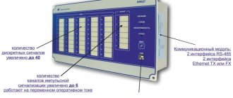
Current backup protection also affects power transformer tripping. The purpose of this device, built on PR 4700 or RZT units, is to back up the main protections in the event of their failure or in the event of loss of opercurrent. The main advantage of this protection is complete independence from the operating current at the substation. The response time of current backup protection is usually maximum (from 3 to 6 seconds).
Minimum voltage protection (MVP) operates in the event of a power transformer de-energization and acts on tripping the low-side circuit breaker before the ATS operates. The operating time of the ZMN can vary from 6 to 20 seconds, depending on the type of load and consumer requirements.
Among the protections acting on the signal, it is worth highlighting overload protection, which operates if the rated power of the transformer is exceeded by an average of 25 percent. The response time of such protection is usually nine seconds.
When the oil temperature in the power transformer tank rises, overheating protection will operate. In this case, the temperature setting depends on the type of cooling of the power transformer. Protection also works on the signal. The response time is also equivalent to the warning alarm time at the substation.
Of course, not all power transformer protections are listed above. But the information provided is quite enough to at least partially understand this issue.
- The most popular breakdowns of electric meters
- How to connect single- and three-phase electric motors?
- Power transformers for power amplifier
- Surge filter and DC cut-off
Basic protection of a 110 kV transformer
Transformer protection complex 110(35)/10(6) kV
In accordance with the requirements of the Electrical Installation Rules, relay protection devices are installed on transformers against the following types of damage and abnormal operating conditions:
· multiphase short circuits in windings and terminals;
· single-phase ground faults in the winding and at the terminals connected to the network with a solidly grounded neutral;
· turn short circuits in windings;
· currents in windings caused by external short circuits;
· currents in the windings caused by overload (overload protection);
· lowering the oil level;
· single-phase ground faults in 3-10 kV networks with an isolated neutral, if the transformer supplies a network in which disconnecting single-phase ground faults is necessary according to safety requirements.
Transformer protections are divided into main and backup.
The main protections include gas protection and differential protection.
Gas protection is designed to protect oil-filled transformers from damage inside the transformer tank, accompanied by the release of gas (short circuit to the housing, turn short circuits, steel fire, etc.), as well as a decrease in the oil level in the transformer.
Transformer differential protection is designed to protect against damage inside the tank, at the transformer terminals or at the busbar section between the current transformers to which the protection is connected.
On low-power transformers, instead of differential current protection, a current cutoff can be installed.
The main protections operate to disconnect the transformer without a time delay.
Backup protections protect the transformer from currents in the windings caused by external short circuits, and also reserve the operation of the main protections.
164. What is the sensitivity coefficient
The term “sensitivity” is usually used to denote a property of relay protection that makes it possible to identify calculated types of damage and abnormal modes of the power system in the coverage area of the relay protection.
In the PUE [1], the concept denoted by the term “sensitivity” [2] is used to characterize any protection, regardless of the voltage of the electrical installation, but there is no definition of the concept denoted by this term in this document.
If the sensitivity of some products can be determined directly, then in relay protection this characteristic is assessed indirectly, and the assessment method depends on the voltage of the electrical installation.
According to the PUE, a coefficient is used to assess the sensitivity of protection in electrical installations with voltages over 1000 V.
The value of the sensitivity coefficient for protections that respond to an increase in the controlled value is found as the ratio of their calculated values within the protected zone to the response setting.
For line current protection, the sensitivity coefficient is generally found using the formula:
It is generally accepted that in the general case such protection will work correctly if the following relation is satisfied:
<
165. Compensation of capacitive ground fault currents. What is it and when is it used?
Electrical networks with a voltage of 6 - 10 kV operate depending on the strength of the ground fault current with the neutral isolated or grounded through arc suppression coils.
For ground fault currents in 6 kV networks of more than 30 A and in 10 kV networks of more than 20 A, according to the PUE, the neutral must be grounded through arc suppression coils to compensate for these currents. The advantage of this operating system is that in the event of a single-phase ground fault, electrical receivers continue to operate normally and, therefore, the power supply to consumers is not disrupted.
Urban cable networks, which have a considerable length, have a large capacity, since the cable itself is in some way a capacitor. Therefore, when a single-phase fault appears in such a network, the ground fault current at the fault location can reach tens or even hundreds of amperes.
With such currents, the cable insulation at the point of damage is quickly destroyed and a single-phase ground fault turns into a two- and three-phase short circuit, which causes a section of the network to be disconnected by a circuit breaker, i.e., an interruption in the power supply to consumers. A stable ground fault in a network with an isolated neutral does not occur immediately, but first in the form of an “intermittent” arc. When the current passes through zero, the arc stops and then reappears. This phenomenon is accompanied by a dangerous increase in voltage relative to ground on undamaged phases and can cause insulation failure in other parts of the network.
In order for the arc occurring at the fault site to go out, it is necessary to compensate for the capacitive ground fault current, for which an inductive grounding arc extinguishing coil is connected to the network zero point.
The coil is a winding with an iron magnetic core, placed in a casing filled with oil. The main winding of the arc suppression coil is tapped for five current values so that the inductive current can be adjusted. In addition to the main winding, the coil has a voltage signal winding, to which a recording voltmeter is connected, from the readings of which the zero-sequence voltage can be determined during operation of the coil. One of the terminals of the main winding of the arc-extinguishing coil is connected to the zero point of the high-voltage winding of a transformer that has a star-zero-delta winding connection circuit, or using a special grounding transformer, and the other terminal of the main winding is connected to the ground.
Protection of transformers from overcurrents in windings caused by external short circuits
To protect step-down transformers from currents caused by external short circuits, maximum current protection is provided without starting or with starting from a minimum voltage relay, which acts to open the circuit breaker. Due to low sensitivity, overcurrent protection without starting from undervoltage relays is used only on transformers with a power of up to 1000 kVA.
To protect step-up transformers from external short circuits. overcurrent protection with starting from a minimum voltage relay or zero-sequence current protection is used.
Maximum current protection with starting from a minimum voltage relay for step-up multi-winding transformers turns out to be quite complex (due to the presence of several sets of minimum voltage relays) and is not sufficiently sensitive to current. In this case, zero sequence current protection is used. The latter is recommended for step-up transformers with a power of 1000 kVA or more with a solidly grounded neutral.
If the protection of step-up transformers does not provide the required sensitivity, then to protect the transformers it is allowed to use current relays for the corresponding protection of generators.
In some cases, negative sequence current protection is used to protect powerful transformers, which is easily combined with similar protection of generators.
On multi-winding transformers with power supply from several sides, to ensure selectivity of action, the protection is directional.
To protect against overload of several transformers operating in parallel with a power of 400 kVA or more, as well as in case of separate operation and the presence of an automatic transfer switch, single-phase maximum current protection acting on the signal is provided.
In unattended substations, protection can be carried out with the effect of automatically unloading or shutting down the transformer.
Source: Electrician School
2554
Bookmarks
Comment 2
Latest publications
Experts from the National Research University "MPEI" discussed the future of engineering education at the Rosatom project session
July 30 at 13:35 28
IPPON at the video surveillance industry event Layta Connect in Kazan
July 29 at 17:27 28
Rockwell Automation presented a film episode about digital transformation with Technologies Added and Sustainder
July 28 at 23:42 38
The SME Corporation will launch a new “umbrella” guarantee mechanism for small businesses in August
July 28 at 23:40 34
"Samsung IT Academy" begins work at the Moscow Energy Institute
July 28 at 23:32 40
Schneider Electric Wins Project of the Year Award for Supply Chain Initiative
July 28 at 23:29 28
The manufacturer of specialized pipes invested 200 million rubles in the development of the enterprise with the support of PSB and the SME Corporation
July 27 at 18:18 44
Congratulations to the Bashkir Generating Company on its 15th anniversary
July 27 at 16:01 38
The unique experimental power plant of the National Research University "MPEI" received a positive conclusion from the state examination
July 27 at 14:44 71
A new point on the map of the Far Eastern projects of ZETO CJSC - a catering center for the seaport of Sukhodol
July 26 at 15:54 42
Comments 2
Anonymous user
Chernobrovov wrote about this and much more in the last millennium.
What's the news? January 16, 2012 at 04:33 pm
Bookmarks
Transformer overload protection
Transformer overload protection - on transformers under the supervision of operating personnel, the overload protection is performed by acting on the signal through a single current relay. To avoid unnecessary signals during short circuits and short-term overloads, the relay circuit provides a time relay, the winding of which must be designed for long-term current flow.
The operating current of the relay protection from overload is selected from the condition of the return of the current relay at the rated current of the transformer:
Iс.з = kots Inom / kv
- where kots = 1.05.
The operating time of the relay protection is selected one step longer than the time of protection of the transformer from external short circuits: tп = tрз + At.
At substations without on-duty personnel, overload protection is performed in three stages. The first stage operates at low overloads and acts on a signal transmitted via telemechanics to the control point with a time delay tп = tрз + At. The second stage, at large overloads, when rapid unloading is required, acts to disconnect some consumers, unloading the transformer to the permissible value. Time delay of the second stage t2 < tadd, where tadd is the permissible overload time determined by the overload characteristic of the transformer. It is advisable to perform the second stage with a current-dependent characteristic corresponding to the overload characteristic of the transformer. The third stage acts to disconnect the transformer if the second stage does not unload. Time delay of the third stage t3 = (t2 + At) < tadd
Fig. 16.16. Placement of protection and current distribution in autotransformer windings during overloads:
a - in a three-phase circuit with one-sided power supply; b - with unilateral nutrition; c - with two-way power supply
On three-winding transformers with the same winding power and one-way power supply, overload protection protection is installed only on the supply winding. If the power of the windings is unequal or with two- and three-way power supply to transformers, overload protection should be installed on all windings.
Overload protection of an autotransformer (AT) is carried out based on the requirements for relay protection transformers, taking into account the characteristics of current distribution in the AT windings and the difference in the rated powers of the windings. Overload protection must respond to overload of the serial (P), common (O) and additional (D) windings AT (Fig. 16.16, a).
The rated (permissible) current in the series winding (related to HV) is determined by the throughput power Sprox, and for the common part of the LV winding (connected in a triangle) - by the calculated (or typical) power Spasch (see Fig. 16.2).
To control the overload of the MV (common) winding, the overload relay RZ must be installed in the zero terminals AT, through which Itotal flows. The overload of the series winding (HV) and the LV winding is controlled by the currents in the HV and LV terminals, respectively. The installation locations of the KA RZ overload relay are shown in Fig. 16.16, a. The need to install a relay protection against overload of one or another AT winding is determined based on an analysis of current distribution under various modes of its operation. So, for example, when the LV winding is overloaded in a mode when the MV side is disconnected, the current on the HV side may be less than the rated one, since the power of the LV winding is equal to Spasch and less than Sprox, which is used to determine Inom on the HV side. It follows that it is necessary to install an overload protection on the LV winding of all ATs.
Considering the current distribution on the step-down AT, which is powered on the HV side (Fig. 16.16.6), we can conclude that when the HV winding is overloaded, the currents in the MV and LV windings may be lower than In. Therefore, on AT, which has power on the HV side, it is necessary install a relay that responds to overload on this side. The specified RP will also protect the common AT winding, since an overload of this winding will be accompanied by an overload of the HV winding. When AT operates in the mode of transmitting electricity from the HV and MV sides to the LV side, the current Itot = IB + IC passes in the common winding (Fig. 16.16, c). Under these conditions, the common winding may become overloaded when there is no overload in the two AT windings.
On AT operating in the specified mode, it is necessary to install an overload protection at the zero outputs of the common winding. The same protection must be provided for ATs in which electricity is transmitted from the MV side simultaneously to the HV and LV. On step-down AT when powered from the HV side, the overload protection must be installed on the HV and LV sides. On the same ATs that have power supply from the MV side, the RZ is also installed on the neutral terminals. On step-up AT, the relay is installed on all three windings.
Protection of power transformers from internal damage
For protection against internal damage (turn short circuits in the windings, accompanied by gas release) and against a decrease in the oil level on transformers with a power of 6300 kVA and above, as well as on transformers with a power of 1000 - 4000 kVA that do not have differential protection or cutoff, and if the maximum current protection has a time delay of 1 s or more, gas protection is used with an effect on the signal in the case of weak gases and a shutdown in the case of intense gas formations. The use of gas protection is mandatory on in-shop transformers with a power of 630 kVA and above, regardless of the presence of other high-speed protection.
Gas protection is installed on transformers, autotransformers and oil-cooled reactors with expanders, and is carried out using float, vane and cup gas relays. Gas protection is the only protection of transformers from a “steel fire” of the magnetic circuit, which occurs when the insulation between the steel sheets is broken.
Gas protection is allowed to operate on the signal both in case of weak and strong gas formation on transformers that have differential protection or cutoff, do not have switches, as well as on in-shop transformers with a power of 1600 kVA or less if there is protection against short circuits from the power source.