Device
Relay control is constantly being improved, new designs are being developed, and new semiconductor circuits are being used. But the operating principle of relay protection remains; it does not depend on progress.
All devices consist of four standard standard parts. These include elements of observation, logic, execution and signaling. The monitoring unit monitors processes and monitors its parameters. The logic block makes a decision if there is a deviation of the measured characteristics from the specified values. The executive unit performs the necessary actions when a command is issued. The signal unit is intended for humans.
Basic connection protection
According to the definition of the PUE (clause 3.2.14) - “Each element of the electrical installation must be provided with basic protection designed to operate in the event of damage within the entire protected element with a time shorter than that of other protections installed on this element.”
Thus, at any connection there is always basic protection (see Myth 2). This is any protection that protects the entire area and acts faster than other protections. Everything is simple and clear. Now examples.
For a 0.4, 6 or 10 kV line, the main protection is overcurrent protection (overcurrent protection). Protects the entire line and works faster than other defenses. Current cut-off operates faster than overcurrent protection, but it only protects part of the line, i.e. cannot be the main defense. The same is with overload protection - although it reacts to damage throughout the entire area, it works much more slowly than MTZ.
Overcurrent protection is generally the main protection for most connections of 0.4-6 kV, with the exception of generators and powerful motors, where the main protection is differential. How does this work? The MTZ remains at the connection, it reacts to all types of short circuit, but another protection appears - differential. Differential protection of an engine or generator also responds to a short circuit throughout the entire section, but responds faster than MTZ. The title of main defense passes to her, and MTZ becomes a reserve.
Another example with the protection of power transformers. Transformers with a power of up to 6.3 MVA have overcurrent protection as the main protection, but starting from 6.3 MVA and above, differential protection is added. It becomes the main one instead of MTZ, and MTZ becomes a reserve one.
Thus, it does not matter on what principle the protection works (see Myth 1), the main thing is that the conditions of clause 3.2.14 are met
Can there be several main protections on one connection? (see Myth 4) Yes, it can.
For example, for oil power transformers 6.3 MVA and more, there are usually 2 main protections - differential and gas. Both fit the definition according to clause 3.2.14 because they operate without a time delay and over the entire protected area. Sometimes 3 main protections are installed at the connection, for example, for AT 220 kV and above high power (two differential and gas)
Types of relay protection
In the last article from the section “Relay Protection and Automation for Beginners” we described the operating principle of relay protection and automation and its purpose. In this material we will consider the main types of protective devices .
Note that relay protection and automation systems are divided into types depending on their purpose and functions. All of them are triggered in one way or another when the value of a certain quantity exceeds the specified parameters, the so-called setpoint .
- The most common type of protection at voltages of 6-10 kV is current protection. According to the principle of operation, this protection reacts when the current exceeds a given set value. One of the most common types of current protection is overcurrent protection (MCP) . MTZ is the most popular type of protection, as it is used almost everywhere.
- Also, there is also Directional overcurrent protection. In addition to the specified parameters, it additionally controls the direction of power.
- For buses and supply lines of substations, additional protection is required - LSHZ (Logical bus protection), which in essence is an acceleration of the overcurrent protection of supply connections.
- Arc protection is necessary for Complete Switchgears ( KRU ) and transformer substations ( KTP ) - it protects them from severe damage and fire. Special optical sensors are activated when illumination increases. In addition, arc protection is equipped with sensors that respond to increased pressure.
- For proper operation, power transformers need cooling - for this they are immersed in special tanks with oil. However, in an emergency situation, the oil can actively release gas, which can lead to a serious accident. Gas protection prevents this situation by monitoring the oil level in the tank.
- Differential protection compares currents in sections between protected lines or equipment. In the event of a short circuit, relay protection disconnects the damaged section. This type of protection is necessary for transformers, generators, motors, overhead power lines, reactors, busbars and busbars.
- Differential phase protection (PDP) protects high voltage power lines and responds to the phase difference of the manipulation currents I1+k*I2 generated by protection semi-sets installed on both sides of the power line. The phase of the manipulation current is transmitted using special high-frequency communication equipment directly through the power wires of the power line itself, which eliminates the need to organize a special communication channel.
- Distance protection will be needed at complex facilities where overcurrent protection and other types of protection cannot cope - in cases where the fault current is comparable to the permissible operating mode of the protected network element. The remote control is capable of calculating the distance from the area where the short circuit occurred and, based on the obtained distance, will operate with a longer or shorter time delay.
| The function of the presented types of protection, as you already understood, is to prevent accidents and turn off damaged areas. However, relay protection and automation is also an automation that serves to independently turn on the power after correcting the problem. |
So, electrical automation also has its own types:
- Automatic transfer of reserve (ATS) will connect spare sources to the power supply if using the main one is impossible. You can learn more about ATS in a special article from our specialists.
- Automatic reclosing (AR) will restart a tripped circuit breaker after a preset time. Automatic reclosure is used on busbars of substations, power lines of 1 kV and above, on transformers and electric motors.
- To unload the network when the frequency decreases, Automatic Frequency Shedding (AFS) - it turns off the least important energy consumers.
- A backup device in case of circuit breaker failure (CBF) is also used for networks whose voltage exceeds 1 kV. If the circuit breaker of the damaged section fails to shut down, the breaker failure circuit breaker will turn off the next one, in order to avoid an accident. More information about breaker failure protection can be found in our review.
Classification of relays according to operating principle
Most protective devices in the form of relays operate on the principles of electromagnetic induction, but the characteristics monitored and the method of response may vary. At the moment, the most popular types of relay protection are those that operate according to the following schemes:
- Gas. This group also includes oil sensor-controllers. In both cases, the task of the device is to detect leaks of transformer coolants. In the event of depressurization of the oil or gas supply channels, the relay automatically turns off the equipment.
- Differential. Such relays are also used in transformers, generators and substations, monitoring current values. The standard response model involves turning off the device if the input values differ greatly from the output values.
- Directional maximum. The simplest relays that activate protection when excessively high voltage, power or current are detected.
- Remote. Blocking relays that detect short circuits and interference in the circuit, and then turn off the equipment.
- Arc. Such relays are installed on complete transformers and substations. Using optical and pressure sensors, they detect signs of fire, triggering the appropriate fire extinguishing systems.
Relay classification
All relays used in the system can be made on the basis of certain equipment. Relay protection can be performed on the following types of relays:
Electromechanical design. The principle of their operation is based on attracting and releasing the moving part of the relay when an electric current passes through the electromagnet coil. In this case, the contacts open or close;
- Semiconductor. They are made on the basis of semiconductor devices (diodes, transistors, thyristors) that act as an electrical switch in the circuit;
- Digital. Based on the operation of microprocessor technology, data processing occurs not in analog, but in digital format, forming a relay protection unit. It is possible to program such digital devices, which adds automation to the operation of relay protection and automation systems without the participation of personnel.
Relay protection devices can also be divided according to the complexity of their application. Simple ones include:
- Maximum current or current cutoff. It is used even in conventional circuit breakers used in everyday life;
- From minimum and maximum voltage. In everyday life, these are so-called barrier devices.
- Differential, which is based on comparing the currents passing through each phase;
- Gas. This is one of the types of transformer protection against leaving the normal operating mode;
- Ground fault. Triggers when insulation is pierced or conductive parts touch the ground.
Complex types of relay protection and automation include:
- Insulation monitoring devices for both direct and alternating current circuits;
- Voltage selection systems;
- Various systems for monitoring temperatures, pressure and other equipment parameters;
- Monitoring and monitoring of the insulation resistance of battery circuits, etc.
To achieve reliability and proper operation of the electrical devices included in this protection, it is necessary that all elements are made of high-quality components such as relays, current transformers, etc. Currently, relay protection is a very popular and in-demand part of the electrical power industry.
TYPES OF INTERMEDIATE RELAYS
The protection and automation circuits are powered from special operational current circuits. By type, the operating current can be alternating or direct.
Sources of direct operating current voltage can be batteries, capacitor banks or rectifiers; the alternating opercurrent busbars are powered by voltage from auxiliary transformers.
Since intermediate relays operate in operational voltage circuits, depending on its type, they are manufactured with coils for direct and alternating current.
RP – 23.
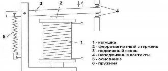
This type of intermediate relay is designed to operate in DC voltage circuits. RP – 23 consists of a voltage coil with a magnetic core. The moving part of the magnetic system is the armature, which, when voltage is applied to the coil, is attracted to the core.
A traverse is mechanically connected to the anchor, on which four contact bridges are attached. Being attracted to the core, the anchor lowers the traverse, compressing the spring on which it is installed. In this case, the normally open contacts close and the normally closed contact opens.
Fixed contacts RP-23 are made in the form of corners made of thin copper plates. Each corner can be installed in one of two ways. Thanks to this, it is possible to obtain four types of combinations of contact group options (p – opening group, z – closing group):
- 1 r, 4 z;
- 2 r, 3 z;
- 3 r, 2 z;
- 4 rubles, 1 z.
This invariance allows this device to be adapted to work as part of any circuit.
When opened, two air gaps are created for each contact, thereby increasing their arc-extinguishing ability.
This property is important when operating a relay device in trip circuits of high-voltage circuit breakers, the solenoids of which have high inductance and maintain the electric arc voltage when the circuit breaks.
RP – 23 is available in various modifications for operation in operational circuits with voltages of 24 V, 48 V, 110 V and 220 V.
RP – 25.
The internal electrical connection diagram of an intermediate relay of this type is similar to RP-23. The RP-25 coil is designed to operate on alternating voltage. Execution options are equipped with coils for voltages of 100 V, 127 V or 220 V.
The working life of the electromagnetic mechanism of the intermediate relays RP-23 and RP-25 is 100,000 operations. The contact group can withstand 10,000 closing and opening cycles with full electrical load in terms of current and voltage.
Main relay protection organs
Launchers
The starting elements continuously monitor the condition and operating mode of the protected section of the circuit and respond to the occurrence of short circuits and violations of the normal operating mode. They are usually performed using relays of current, voltage, power, etc.
Measuring organs
Measuring bodies determine the location and nature of the damage and make decisions on the need for protection. Measuring elements are also performed using relays for current, voltage, power, etc. The functions of the starting and measuring element can be combined in one element.
Logical part
The logical part is a circuit that is triggered by triggering elements and, analyzing the actions of the measuring elements, performs the intended actions (turning off switches, starting other devices, sending signals, etc.). The logical part consists mainly of time elements (timers), logical elements, intermediate and indicating relays, discrete inputs and analog outputs of microprocessor protection devices.
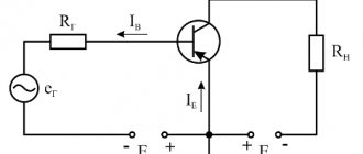
Example of the logical part of relay protection
Current relay coil K1
(contacts A1 and A2) is connected in series with the secondary winding of the current transformer
TA
.
During a short circuit, in the section of the circuit in which the current transformer is installed, the current strength increases, and the current strength in the secondary circuit of the current transformer increases in proportion to it. When the current reaches the set value of relay K1
, it will operate and close the operating contacts (11 and 12).
The circuit between the +EC
and
-EC
will close and power the
HLW
.
This diagram is given as a simple example. More complex logic circuits are used in operation.
Types of protection in electrical circuits
If the normal operating mode of the electric drive is violated, electrical protection is used to prevent failure of electrical equipment and increase the reliability of the circuit.
The following types of protection are used in electric drive circuits:
- zero;
— maximum current;
— minimum current;
— thermal;
- special.
Zero protection provides protection against self-starting of motors in the event of an excessive decrease or short-term disappearance of the supply voltage.
Protection is provided by AC line contactors and magnetic starters and circuit breakers.
When controlled by a command device, a voltage protection relay is used.
| Rice. Units of zero protection circuits for AC and DC motors using linear contactors ( a ) and voltage relays ( b-d ) |
| Rice. Units of zero protection circuits for AC ( a ) and DC ( b ) motors using a QF with minimal tripping |
Overcurrent protection – from short-circuit.
It is carried out by fuses, maximum current relays, and circuit breakers.
| Rice. Units of overcurrent protection circuits for AC ( a ) and DC ( b ) motors, as well as circuits of the control circuit ( c ) carried out by fuses |
| Rice. Units of overcurrent protection circuits for AC ( a ) and DC ( b ) motors and a control circuit ( c ) carried out by automatic circuit breakers with overcurrent releases |
Thermal protection – protection against overloads.
It is carried out by electrothermal relays, maximum current relays and automatic switches with thermal releases.
The protection operates when the engine is disconnected from the mains supply and upon subsequent activation requires operator intervention.
| Rice. Components of thermal protection circuits for AC ( a, b ) and DC ( c FR thermal relays affecting the linear contactor ( d ) and voltage relay ( e ) |
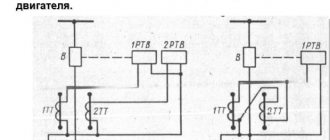
When working in RCC, when the heating characteristics of the relay and the motor are different, its overload protection should be carried out using maximum current relays. The relay setting current is applied depending on the permissible motor overload in relation to the rated motor current.
I
mouth = (1.2 – 1.3)
I
rated motor.
Often such protection is used to protect IM from overloads and operation on two phases, then the relay current is taken from the condition
I
2f >
I
y >
I
zf,
where I
2ph,
I
3ph – motor current when operating on two and three phases
Since the setting current is lower than the starting currents, during the starting period the contacts of the current relay are shunted by the contacts of the time relay CT.
| Rice. Nodes of circuits for switching on thermal protection contacts carried out by maximum current relays FA1 and FA2 during intermittent engine operation | Rice. Units of thermal protection circuits for AC ( a ) and direct ( b ) current motors, carried out by automatic circuit breakers with thermal releases |
3-1. Current cut-off and maximum current protection of single lines 35 and 110 kV
Basic calculation conditions. The basic conditions for calculating the maximum current protection of current cut-offs, set out in Chapter 1, are valid for 35 and 110 kV lines without branches and with branches. In expression (1-1), the self-starting coefficient kсзп is determined by the total self-starting current of the load of all transformers connected to the protected line and to all subsequent (in the direction of current) lines of the same voltage. To do this, in the design diagram, all loads connected to each transformer are represented by the resistance of a generalized or household load, reduced to the operating maximum power of the transformer. High voltage motors are counted separately.
Requirements for relay protection
Selectivity (selectivity)
Selectivity is a property of relay protection that characterizes the ability to identify exactly the damaged element of the electrical power system and disconnect this element from the serviceable part of the electrical power system (EPS). Protection can have absolute or relative selectivity. Protections with absolute selectivity only operate in the event of damage in their zone. Protections with relative selectivity can act in case of damage not only in their own zone, but also in the neighboring zone. And the selectivity of switching off a damaged EPS element is ensured by additional means (for example, a response time delay).
Performance
Speed is a property of relay protection that characterizes the speed of identifying and separating damaged elements from the electrical power system. An indicator of performance is the protection response time - this is the time interval from the moment the damage occurs to the moment the damaged element is separated from the network.
Sensitivity
Sensitivity is a property that characterizes the ability of relay protection to detect faults at the end of its established coverage area in the minimum operating mode of the power system. In other words, this is the ability to sense those types of damage and abnormal conditions for which it is designed, in any operating conditions of the protected electrical system. The sensitivity indicator is the sensitivity coefficient, which for maximum protections (responsive to an increase in the controlled value) is defined as the ratio of the minimum possible signal value corresponding to the monitored damage to the response parameter (setpoint) set on the protection.
Reliability
Reliability is a property that characterizes the ability of relay protection to operate correctly and reliably in all modes of the controlled object under all types of damage and abnormal modes for which this protection is intended, and not to operate under normal conditions, as well as in such damage and violations of the normal mode, when for which this protection is not provided. In other words, reliability is a property of relay protection that characterizes its ability to perform its functions under any operating conditions. The main indicators of reliability are uptime and failure rate (number of failures per unit of time).
The problem of assessing the sensitivity of relay protection
One of the main requirements for relay protection is the requirement of sensitivity. The sensitivity of the protection must be sufficient for its reliable operation during a short circuit at the end of the zone established for it in the minimum mode of the power system and during short circuits through a transition resistance (through an arc). In domestic practice, the sensitivity coefficient is used as a measure of sensitivity; this is regulated in the PUE.
Quote from clause 3.2.20 of the PUE:
“The sensitivity of the main types of relay protection should be assessed using a sensitivity coefficient determined by:
- for protections that respond to quantities that increase under damage conditions - as the ratio of the calculated values of these quantities (for example, current or voltage) for a metal short circuit within the protected area to the protection response parameters;
- for protections that respond to quantities that decrease under damage conditions - as the ratio of response parameters to the calculated values of these quantities (for example, voltage or resistance) for a metal short circuit within the protected area.”
So, according to regulatory requirements, the sensitivity of various types of protection should be assessed using the sensitivity coefficient determined for a metal short circuit. But how objective is this indicator? Is it correct to compare the sensitivity, for example, of a current relay (RT) and a resistance relay (RS) according to their sensitivity coefficients? The answer is no, wrong. Let us substantiate this statement using a simple example of a three-phase short circuit on the HV side of the transformer of the generator-transformer unit. The parameters of the protected object are as follows.
- Generator: type TVF-120-2U3 rated apparent power Snom = 125 MVA rated active power Pnom = 100 MVA subtransient inductive reactance X ”d* =0.192 pu.
- Transformer: type TDTs-125000/220 rated power Sn = 125 MVA rated voltage 242/10.5 kV short circuit voltage uk = 11%
- System: value of three-phase short-circuit current at the terminals of a 220 kV transformer – 21128 A, rated voltage – 235.5 kV
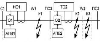
The equivalent circuit of the protected object with a metal three-phase short circuit on the HV side of the transformer (in direct sequence) is shown in Fig. 1. The installation location of the protection is indicated by a flag. The coordinate of the damage location is designated as xf.
Rice. 1. Equivalent circuit for a three-phase short circuit on the HV side of the block
Calculated equivalent circuit parameters:
- Generator EMF Eg = 230/sqrt(3) = 133 kV
- equivalent EMF of the system Ec = Eg = 133 kV
- Generator resistance X”d =81.25 Ohm
- transformer resistance Xt = 46.55 Ohm
- equivalent system resistance Xс = 6.43 Ohm
The current of a metal three-phase short circuit on the HV side of the block, calculated according to the equivalent circuit, is equal to Ikz = 1039 A. Let us calculate the settings RT and RS based on the condition of equality of their sensitivity coefficients Kch for a short circuit at the specified point (let us assume for both relays Kch = 1.5). RT operation current at Kch = 1.5:
Israb = Ikz/Kch = 1039/1.5 = 693 A.
RS operation resistance at Kch = 1.5:
Zwork = Xt · Kch = 46.55·1.5 = 69.83 Ohm.
Let the RS be non-directional with a circular response characteristic (Fig. 2).
Rice. 2. Characteristics of RS operation
Now let’s find out how sensitive RT and RS with the same Kch = 1.5 really are to three-phase short circuits on the HV side of the protected generator-transformer unit. It is obvious that both relays in the case of a metal three-phase short circuit at a given point will operate reliably. What short circuit must occur for the selected RT and RS to be insensitive to it and refuse to operate? The only short-circuit mode parameter that affects the sensitivity of the relay in our example is the transition resistance at the fault location Rf. As Rf increases, at a certain value the protections stop working. For each specific short circuit point this value of Rf will be different. If for each short circuit point xf within the protected zone we obtain the Rf values at which the protection stops working, then the resulting dependence will represent a very specific measure of the sensitivity of this protection, and with a clear physical meaning. Let's call this dependence the characteristic of the sensitivity of the protection (relay) to the transient resistance. For the considered RT and RS, the characteristics of sensitivity to transition resistance are shown in Fig. 3. Coordinate xf = 0 p.u. corresponds to the LV side of the block transformer, and xf = 1.0 pu. – HV side. What information can be obtained from the characteristics in Fig. 3? Firstly, it turns out that RT and RS with the same sensitivity coefficient for a metal short circuit on the HV side of the block transformer have different sensitivity to the transition resistance, not only for a short circuit on the HV side, but also within the entire transformer of the block. Secondly, the sensitivity of RT to transient resistance is more than 2 times higher than that of RS.
Thus, it turns out that the sensitivity coefficient indicator is not a completely objective measure of the sensitivity of the measuring organs of relay protection. It turns out that if we want to get the real picture, then it is impossible to compare the sensitivity of different relays (of different types, with different forms of response characteristics) using the sensitivity coefficient.
Rice. 3. Characteristics of sensitivity of RT and RS to transient resistance
Recommended Posts
- Modeling relay protection in Simulink
The Matlab/Simulink software package allows you to simulate not only electrical networks, but also much more, including... - History of relay protection As far as we know, until the end of the nineteenth century there were neither relay operators nor relay protection...
- Modeling relay protection in Simulink The Matlab/Simulink software package allows you to simulate not only electrical networks, but also much more, including...
Literature
- Fedoseev A. M. “Relay protection of energy systems”: Textbook for universities. M.: “Energy”, 1976. − 560 p. with ill.
- Chernobrovov N.V., Semenov V.A. “Relay protection of energy systems”: Textbook. manual for technical schools. - M.: Energoatomizdat, 1998. −800 pp.: ill.
- Pavlov, G. M. “Automation of energy systems”: Textbook / G. M. Pavlov. - Leningrad: Leningr Publishing House. Univ., 1977.—237 p. : ill.— Bibliography: p.233-234.
- Bulychev, A. V. Relay protection of electric power systems: textbook / A. V. Bulychev, V. K. Vanin, A. A. Navolochny, M. G. Popov. - St. Petersburg: Polytechnic Publishing House. University, 2008. - 211 p.
- RD 153-34.0-04.418-98 “Standard regulations on relay protection and electrical automation services.”
- Shneerson E.M. “Digital relay protection” - M.: Energoatomizdat, 2007. −549 pp.: ill.