Alternative energy is not only a fashionable activity that is strongly supported by various environmental movements. Correct application of appropriate technologies will ensure complete or partial autonomy of energy supply. A high-quality generator using neodymium magnets will save significant money, taking into account current tariffs. This publication will help you assemble a functional design without errors.
A powerful permanent magnet generator provides the necessary power supply without connecting to centralized networks
Definitions and formulation of tasks
In this project, alternating current is obtained through induction. It is formed when a conductor moves in magnetic field lines. This movement is achieved using a rotor, which is driven by the force of the wind.
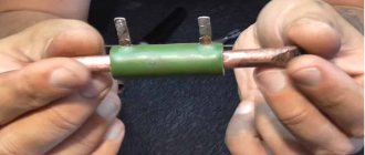
Power supply diagram
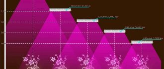
This figure explains the composition of a typical installation. At high altitudes, the wind force increases, so the permanent magnet alternator is mounted on a suitable strong support. For better stability, it is secured with stretch marks. The main support can be made with attachment to a mortgage in a concrete foundation.
A mechanism for servicing working units during operation should be considered. In large installations, ladders are secured to supports for personnel access. Relatively smaller structures of the household category are made collapsible. Sometimes a rotating support assembly is used to move the rack to a horizontal position if necessary.
The windmill unit is mounted on a bearing to ensure unhindered 360-degree rotation. To automatically turn in the desired direction, install the tail plate vertically, as in a conventional weather vane. Hurricane winds can spin the rotor too quickly. To prevent damage in such situations, a special brake is used. Particularly large structures are equipped with rotating blades.
Strong wind protection with folding mechanism and return spring
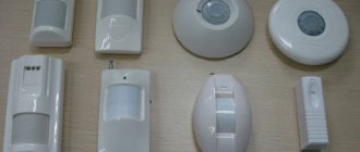
The wind magnetic generator does not have constant parameters. For this reason, an electrical energy storage device is necessary. The resulting alternating current is rectified. Next, a device for operational monitoring (ammeter) is installed in the circuit. The next block, the controller, ensures that the connected battery is properly charged.
The accumulated energy can be used directly to power lamps. Other consumers are connected through a converter (inverter), which generates an alternating voltage with the necessary parameters at the output.
Legality: How powerful a device can be made?
The production and installation of a homemade wind generator is not subject to administrative or criminal penalties if its power is no more than 5 kW.
Also, taxation of produced electricity is not provided, since its resources are spent on domestic needs at home. For the same reason, the installation of a wind turbine does not require approval from the local energy company. However, before manufacturing a windmill, you should check the presence or absence of restrictive subject and municipal regulations.
Questions may also arise from neighbors who may experience inconvenience associated with the operation of the windmill. Therefore, if you are going to create a wind generator, then you need to pay attention to such parameters as:
- Mast height. There are certain restrictions on the height of these buildings. For example, a building with a height of more than 15 meters cannot be installed near bridges, airports and tunnels.
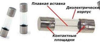
- Noise from gearbox and blades. It is necessary that these characteristics do not exceed noise standards. The parameters of the generated noise can be recorded using a specialized device; the readings are better documented.
- On-air interference. Some windmills can create TV interference, so it is better to provide protection against this.
- Environmental Services Claims. These organizations may interfere with the operation of a wind turbine if it interferes with the migration of migratory birds. But, since the height of homemade windmills is usually small, this problem will not arise.
Main project parameters
Homemade generator
After familiarizing yourself with the general principles, you need to clarify your personal requirements. It is not easy to make a powerful wind generator with your own hands, so experiments begin with the simplest small models. However, with proper preparation, it is quite possible to begin implementing a project to fully supply a certain property with electricity.
It is relatively easy to create a single-phase generator. However, significant current drops are formed at the output of such a device. This process is accompanied by strong vibrations and noise. Such a sound will disturb the owner himself. It will cause discontent among the neighbors. If the standards established by current legislation are exceeded, the installation will have to be dismantled.
To eliminate the listed disadvantages and at the same time increase efficiency by 40-50%, preference is given to a three-phase circuit. If there is no suitable ready-made electric asynchronous motor, you can create it yourself.
Main components, single- and three-phase generator winding connection diagrams
The photo shows an example with rotors (1), which are made of neodymium magnets. The following pictures show the copper coil stator at the manufacturing stage (2) and after creating a solid block with epoxy resin.
Ecowatt: Do-it-yourself wind generator with an axial generator on neodymium magnets
Homemade windmill
I live in a small town in the Kharkov region, a private house, a small plot. I myself, as my neighbor says, am a walking generator of ideas, since almost everything on my farm is made with my own hands
. The wind, although small, blows almost constantly, and thus tempts you to use your energy.
After several unsuccessful attempts with a tractor self-exciting generator
the idea of creating a wind generator stuck in my brain even more. I started searching and after two months of searching on the Internet, many downloaded files, reading forums and advice, I finally decided on building a generator.
The design of a wind turbine was taken as a basis
Burlak Viktor Afanasyevich https://rosinmn.ru/sam/burlaka with minor design changes.
The main task was to build a generator
from the material that is available, with a minimum of costs. Therefore, anyone who tries to make such a design should start with the material that he has, the main desire is to understand the principle of operation.
To make the rotor, I used a sheet piece of metal 20mm thick (which was what it was), from which, according to my drawings, my godfather carved and marked two disks with a diameter of 150 mm into 12 parts and another disk for a screw, which he marked into 6 parts with a diameter of 170 mm.
I bought 24 pieces online. neodymium disk magnets measuring 25x8 mm, which I glued to the disks (the markings really helped). Be careful not to put your fingers in!
Before gluing the magnets to the steel disk with a marker, mark the polarity on the magnets, this will greatly help you avoid mistakes. After placing the magnets (12 pieces per disk and alternating polarity), I filled them halfway with epoxy resin.
Click on the picture to view in full size.
To manufacture the stator, I used PET-155 enamel wire with a diameter of 0.95 mm (bought from a private enterprise Harmed). I wound 12 coils of 55 turns each, the thickness of the windings was 7 mm. For winding I made a simple collapsible frame. I wound the coils on a homemade winding machine (I did it back in the times of stagnation).
Then I placed 12 coils according to the template and fixed their position with fabric-based electrical tape. The coil terminals were wired sequentially, beginning to beginning, end to end. I used a 1-phase switching circuit.
To make a mold for filling the coils with epoxy resin, I glued together two rectangular pieces of 4 mm plywood. After drying, a strong 8 mm blank was obtained. Using a drilling machine and a device (ballerina), I cut a hole with a diameter of 200 mm in the plywood, and from the cut disk I cut out a central disk with a diameter of 60 mm. I covered the pre-prepared rectangular chipboard blanks with film and secured them along the edges with a stapler, then placed the cut-out center (covered with tape) according to the markings, as well as the cut-out blank wrapped with tape.
I filled the mold halfway with epoxy resin, put fiberglass on the bottom, then coils, fiberglass on top, added epoxy, waited a little and pressed it on top with a second piece of chipboard also covered with film. After hardening, I removed the disk with the coils, processed it, painted it, and drilled holes.
The hub, as well as the base of the rotary unit, was made from a tubing drill pipe with an internal diameter of 63 mm. Sockets for 204 bearings were made and welded to the pipe. A cover with an oil-resistant rubber gasket is screwed on the back side with three bolts, and a cover with an oil seal is screwed on the front side. Inside, between the bearings, through a special hole, I poured semi-synthetic automotive oil. I put a disk with neodymium magnets on the shaft, and since it was not possible to make a groove for the key, I made recesses on the shaft half the diameter of the ball with 202 bearings, i.e. 3.5 mm, and on the disks I drilled a groove with a 7 mm drill, having previously turned out the barrel and pressed it into the disk. After removing the barrel, a smooth, beautiful groove for the ball was obtained in the disk.
Next, I secured the stator with three brass pins, inserted an intermediate ring so that the stator would not rub, and put on a second disk with neodymium magnets (the magnets on the disks should have the opposite polarity, i.e. attract each other) Be very careful with your fingers here!
The screw was made from a sewer pipe with a diameter of 160 mm https://Ekovatt.rf/alternative_energy/wind_energy/d120/
By the way, the screw turns out to be quite good. Therefore, the last screw was made from a 1.3 m aluminum pipe (see above)
I marked the pipe, cut out the blanks with a grinder, tightened them at the ends with bolts and processed the package with an electric planer. Then I unrolled the package and processed each blade separately, adjusting the weight on an electronic scale.
Protection against hurricane winds is made according to the classic foreign design, i.e. the axis of rotation is offset from the center. Here is the link to the site https://www.otherpower.com/otherpower_wind.html
Those who want to know more will find all the questions they need here, and completely free of charge! This site helped me a lot, especially with the tail drawings. Here is an example of drawings from this site.
I adjusted my windmill tail using the sawing method.
The entire structure is mounted on two 206 bearings, which are mounted on an axis with an internal hole for the cable and welded to a two-inch pipe.
The bearings fit tightly into the wind turbine housing, which allows the structure to rotate freely without any effort or play. The cable runs inside the mast to the diode bridge. (See drawings above)
the photo shows the original version
To manufacture the wind head, not taking into account two months of searching for solutions, it took a month and a half, now we are in the month of February, it looks like there has been snow and cold all winter, so I haven’t carried out the main tests yet, but even at this distance from the ground, the 21-watt car light bulb burned out. I'm waiting for spring, preparing the pipes for the mast. This winter has flown by quickly and interestingly for me.
A little time has passed since I posted my windmill on the site, but spring hasn’t really come, it’s still impossible to dig the ground to wall up a table under the mast - the ground is frozen and there’s dirt everywhere, so there’s no time for testing on a temporary 1.5 m stand there was plenty, but now more details.
After the first tests, the propeller accidentally caught the pipe, I was trying to fix the tail so that the windmill would not move out of the wind and see what the maximum power would be. As a result, the power managed to register approximately 40 watts, after which the propeller safely shattered into pieces. Unpleasant, but probably good for the brain. After that, I decided to experiment and wound a new stator. To do this, I made a new mold for filling the coils. I carefully lubricated the mold with automotive lithol so that excess would not stick. The coils have now been slightly reduced in length, thanks to which 60 turns of 0.95 mm now fit into the sector. winding thickness 8 mm. (in the end the stator turned out to be 9 mm), and the length of the wire remained the same.
The screw is now made from a more durable 160 mm pipe. and three-blade, blade length 800 mm.
New tests immediately showed the result, now GENA produced up to 100 watts, a halogen car light bulb of 100 watts burned at full intensity, and in order not to burn it out in strong gusts of wind, the light bulb was turned off.
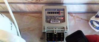
Measurements on a 55 Ah car battery.
Well, it’s already mid-August, and as I promised, I’ll try to finish this page.
First what I missed
The mast is one of the critical structural elements
One of the joints (a pipe of a smaller diameter goes inside a larger one)
and swivel unit
now the rest
3-blade propeller (red sewer pipe with a diameter of 160 mm.)
I’ll start by changing several propellers and settling on a 6-bladed one with an aluminum pipe with a diameter of 1.3 m. Although the propeller with a 1.7 m PVC pipe gave more power.
The main problem was to force the battery to charge from the slightest rotation of the screw, and here a blocking generator came to the rescue, which, even with an input voltage of 2 V, gives a charge to the battery - albeit with a small current, but better than a discharge, and in normal winds all the energy goes to the battery comes through VD2 (see the diagram), and there is a full charge.
Here you can read everything https://vrtp.ru/index.php?CODE=article&act=categories&article=1759
The structure is assembled directly on the radiator using semi-mounted installation
I also used a homemade charge controller, the circuit is simple, I made it as always from what was at hand, the load is two turns of nichrome wire (with a charged battery and a strong wind it heats up to red) All transistors were installed on radiators (with a reserve), although VT1 VT2 practically do not heat up, but VT3 must be installed on the radiator! (when the controller operates for a long time, VT3 heats up decently)
Controller circuit
photo of the finished controller
The diagram for connecting a windmill to a load looks like this:
photo of the finished system unit
My load, as planned, is the light in the toilet and outdoor shower + street lighting (4 LED lamps that turn on automatically via a photo relay and illuminate the yard all night, with sunrise the photo relay is triggered again, which turns off the lighting and charges the battery. And this is on the dead Battery (removed from car last year)
In the photo the protective glass has been removed (photo sensor at the top)
I bought a photo relay ready for a 220 V network and converted it to power from 12 V (I bridged the input capacitor and soldered a 1K resistor in series with the zener diode)
Now the most IMPORTANT part!
From my own experience, I advise you to start by making a small windmill, gain experience and knowledge and see what you can get from the winds of your area, because you can spend a lot of money, make a powerful windmill, but the wind power is not enough to receive the same 50 watts and your windmill will be an underwater type boats in the garage.
The simplest anemometer. Square side 12 cm by 12 cm. A tennis ball is tied on a 25 cm thread.
We never think about how strong even a small breeze can be, but it’s worth looking at how fast a turbine sometimes spins and you immediately understand how powerful it is.
Wind, you are mighty wind... (photo from the yard)
The windmill modernization process is complete, this is what it looks like at this stage. The video shows its operating mode (I filmed it with a camera, so the discreteness of the screw is visible, in fact it is spinning as if it had been blown up). In very low winds the BLOCKING GENERATOR works.
Do-it-yourself wind generator with an axial generator on neodymium magnets
!
Good luck to all!!!
(do-it-yourself wind generator, windmill with an axial generator, do-it-yourself windmill, neodymium magnet generator, homemade windmill, self-exciting generator)
The article is posted with the permission of the author, the original is here: https://valerayalovencko.narod2.ru/
Russian portal about alternative energy and eco technology
Electrical and technical parameters of the generator
The voltage is calculated using the formula:
AC generator
U=2*Ch*KP*KK*KV*MI*P, where:
- U – voltage in Volts;
- H – frequency of rotation of the generator rotor per second;
- KP – number of magnetic poles;
- КК – number of induction coils in the stator;
- KV – the number of turns of the conductor in one induction coil;
- MI is the magnetic induction in T, which is formed in a standard gap (2 mm);
- P – surface area of one neodymium magnet, in sq. m.
If simple coils are used, a magnetic induction of 0.5 Tesla is taken for calculation. When adding an electrical steel core, the value is increased to 0.7-0.9 T.
For your information. The formula is valid when connecting the windings in a triangle. If a three-phase generator is assembled using a star circuit, the resulting value is multiplied by a correction factor of 1.7.
After calculating the voltage, you need to find out the resistance in the windings. After this, it will be easy to determine the current and power. For a copper conductor, the resistivity is 0.0175 Ohm per mm2/meter. To calculate the total value, use the formula:
C= (US*D)/PP, where:
- C – resistance, in Ohm;
- US – resistivity of a certain material;
- D – conductor length in meters;
- PP – conductor cross-sectional area, mm sq.
To calculate the current, subtract the voltage of the battery connected for charging from the voltage of the magnetic generator at idle. The resulting value is divided by the resistance value calculated using the previous formula.
Increasing/decreasing the speed changes the current accordingly while keeping the voltage at the battery terminals constant. To calculate the performance of a wind turbine in different modes, use the standard formula:
P=I*U, where:
- P – power, Watt;
- I – current strength, Ampere;
- U – voltage, Volt.
Calculation and features of coil winding
Newly-minted “Kulibins” rarely think about how important calculations are so that a low-speed axial generator for a windmill works with maximum efficiency. In principle, I am not a special exception. Therefore, when making calculations, I used the experience of others, thanks to which it became clear that a low-speed generator will be able to charge a 12-volt battery at 100-120 revolutions of the screw if there are from 1000 to 1200 turns of enamel wire in all stator coils.
Source usamodelkina.ru
Share
Advice! It is recommended to use the wire as thick as possible to reduce resistance as much as possible. In my case it was 1.5 mm.
A homemade machine was used to wind the coils, since it is almost impossible to do such work efficiently by hand. The result was ellipsoidal-shaped windings, the internal holes of which were slightly larger than the width of the magnets, in order to more efficiently use the front parts of the coils.
Features of the rotor and stator
Tesla Generator
To make an effective generator using neodymium alloy magnets with your own hands, consider the following recommendations when assembling:
- To increase strength, the disc is made of steel. Its thickness is made no less than that of the magnets themselves. Otherwise, part of the force field will dissipate. If the proportions are observed correctly, the sewing needle will not be attracted to the reverse side of the assembled product;
- The distance between individual magnets is made equal to or more than half the width of the products;
- The thickness of the assembled stator is made equal to or less than the thickness of neodymium magnets;
- A three-phase magnetic generator is made in proportions of 3 to 3 or 4 to 3 (the number of magnets/induction coils, respectively).
For your information. The magnets are attached, strictly observing the alternation of poles.
To avoid mistakes, marks are made in advance with a marker on the corresponding edges.
Neodymium magnets in design
This part is the most expensive in the entire structure - this is undoubtedly a disadvantage. But, on the other hand, humanity has not yet come up with a more powerful and accessible magnet. Nowadays it’s not difficult to get them: size, strength, mass - if only you had the desire and money.
Neodymium magnets come in different sizes and power
Our wind generator uses neodymium magnets with a diameter of 25 millimeters and a height of 8 millimeters. Quantity: 20 magnets on disks. Installation of magnets is the most important process after maintaining accuracy. It is best to use strong glue, which it is advisable to first test for holding strength. The magnets must be arranged in a circle with obligatory alternation of poles.
You can draw the hub, you can do everything on paper in advance - in any case, you can’t make a mistake. The pole can be marked with a marker on the surface of the magnet, then the likelihood of error is reduced to zero. After gluing, the surface of the disc is filled with epoxy resin. A bead is wound around the edges of the disk. This can be a thin strip of veneer or rough cardboard, or flexible plastic can be used. Some people glue the edges with plasticine.
How to agree on the parameters of functional parts
The energy potential of the blades must correspond to a specific asynchronous motor or a self-assembled rotor with magnets. In case of significant deviations, in order to obtain sufficient electrical power, it will be necessary to create new products with the required parameters. The reverse situation is also unacceptable. Too large blades are not able to rotate quickly. Strong winds increase the risk of destruction of such structures.
To avoid mistakes, make a table with equipment operating modes at different rotation speeds in increments of 50-100 rpm. Next, they use specialized calculators that, based on the given values, calculate the geometric parameters of the screw. These products are created from suitable wood, metal, and plastic. Standard polyvinyl chloride pipes for external sewer networks are suitable as blanks.
Stator assembly
To begin with, I had to create a mold from plywood with a lid and bolts in the “ears” of the stator for casting the main part of my homemade product. Then I proceeded according to the following scheme:
- laid fiberglass on the bottom of the mold;
- I treated everything with Vaseline;
- laid out the coils and brought the ends of the wires outside the mold;
- poured epoxy with talc filler;
- covered the coils on top with a layer of fiberglass;
- I closed the mold with a lid and tightened the bolts, making a kind of press.
Attention! The thickness of the stator should be equal to the thickness of the magnets used to create the windmill.
Source e-veterok.ru
Share
After the epoxy resin had hardened, I disassembled the mold, made sure there were no cracks, soldered the ends of the coils with an asterisk and began the final assembly of the structure. At the end of the work, tests were carried out, during which it turned out that the homemade generator, even when rotated manually, produces a voltage of up to 40 V with a current of up to 10 A.
Conclusions and additional information
Using a gearbox and careful calculation of the blades, you can create a low-speed, low-noise, low-speed generator using neodymium magnets. Modern electronic components and corresponding circuitry will help create an inverter with high efficiency. New battery models perform their functions flawlessly, without routine maintenance, and retain their useful functions after hundreds of recharge cycles.
Wind generators with a vertical axis of rotor rotation
To get acquainted with existing installations, you can see the implemented projects of Sergei Savchenko, Alexander Sedov, Valery Yalovenko, Victor Burlak. Their ideas can be transformed taking into account personal capabilities and preferences. It’s easy to simplify calculations using specialized calculator programs that can be quickly found on the Internet. In any case, the magnetic generator should be considered in conjunction with other parts of the off-grid power supply system to ensure good coordination.
Buy or make it yourself
This issue can be resolved independently; there are enough descriptions on the Internet, so doing all the work yourself is not so difficult. Detailed reports are provided, all that remains is to repeat all the operations. And if you study the circuits, errors and difficulties in detail, you can build a wind generator relatively quickly, which will be more reliable and durable. Of course, you can buy a ready-made design: it will even be better to some extent. However, if there are opportunities, then why not try your hand?
Where to begin
The basis of homemade wind generators is a car hub along with brake discs. Firstly, it does not require rework or complex additions. Secondly, it’s easy to get. Usually the hub is taken second-hand, so it must be disassembled and cleaned.
Cleaning is done thoroughly: a steel brush or an attachment on a LNA or drill will help to perform the cleaning in the best possible way. Painting the hub is a must. You need to choose high-quality paint to maximize its service life.