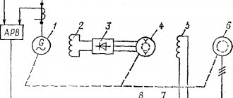
Various machine tools often require stepless control of the drive speed within a wider range than can be achieved by flux control of a DC shunt motor. In these cases, more complex electric drive systems are used. In Fig. Figure 1 shows a diagram of an adjustable electric drive using a generator - engine system (abbreviated G - D). In this system, an asynchronous motor AD continuously rotates a direct current generator G with independent excitation and an exciter B, which is a low-power direct current generator with parallel excitation.
The DC motor D drives the working part of the machine. The excitation windings OVG of the generator and OVD of the engine are powered by exciter B. By changing the resistance of the excitation circuit of the generator D with rheostat 1, they change the voltage supplied to the motor armature D, and thereby regulate the engine speed. At the same time, the engine operates with full and constant flow, since rheostat 2 is removed.
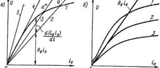
When the voltage U changes, the rotational speed n 0 of the ideal idling speed of the engine D changes. Since the engine flux and the resistance of its armature circuit do not change, the angular coefficient b remains constant. Therefore, straight-line mechanical characteristics corresponding to different U values are located one below the other and parallel to each other (Fig. 2).
They have a greater slope than the characteristics of the same electric motor powered from a DC network, since in the G-D system the voltage U at a constant excitation current of the generator decreases with increasing load according to the dependence:
where Eg and r g are, respectively, e. d.s. and internal resistance of the generator.
By analogy with asynchronous motors, we denote
This value characterizes the decrease in engine speed when the load increases from zero to nominal. For parallel mechanical characteristics
This value increases as n0 decreases. At large values of sн, the specified cutting conditions will change significantly with random load fluctuations. Therefore, the voltage regulation range usually does not exceed 5:1.
As the rated power of motors decreases, the voltage drop across them increases and the mechanical characteristics become more inclined. For this reason, the voltage regulation range of the G-D system is reduced as the power decreases (at powers less than 1 kW to 3:1 or 2:1).
As the magnetic flux of the generator decreases, its voltage is more affected by the demagnetizing effect of the reaction of its armature. Therefore, the characteristics related to low engine speeds actually have a greater slope than the mechanical characteristics.
Expansion of the control range is achieved by reducing the magnetic flux of the motor D by means of rheostat 2 (see Fig. 1), carried out at full generator flow. This method of speed control corresponds to characteristics located above the natural one (see Fig. 2).
Before starting the engine, rheostat 2 (see Fig. 1) is completely removed, and the engine flow reaches its highest value. Then rheostat 1 increases the excitation of generator G. This causes an increase in voltage, and the speed of engine D increases. If the OVG winding is switched on immediately to the full voltage UB of exciter B, then the current in it, as in any circuit with inductance and active resistance, will increase:
where rв is the resistance of the excitation winding, LB is its inductance (we neglect the influence of saturation of the magnetic circuit).
In Fig. 3, a (curve 1) shows a graph of the excitation current versus time. The excitation current increases gradually; the rate of rise is determined by the relation
where Tv is the electromagnetic time constant of the generator excitation winding; has the dimension of time.
Rice. 3. Change in excitation current in the G-D system
The change in generator voltage during startup has approximately the same character as the change in excitation current. This makes it possible to automatically start the engine directly with rheostat 1 removed (see Fig. 1).
The increase in the generator excitation current is often accelerated (forced) by applying a voltage exceeding the rated voltage to the excitation winding at the initial moment. The process of increasing excitation will proceed along curve 2 (see Fig. 3, a). When the current strength in the winding reaches a value Iв1 equal to the steady-state excitation current strength at the rated voltage, the voltage on the excitation winding is reduced to the rated value. The rise time of the excitation current to the nominal value is reduced.
To force the excitation of the generator, the exciter voltage B (see Fig. 1) is selected 2-3 times higher than the rated voltage of the generator excitation winding and an additional resistor 4 is introduced into the circuit. By short-circuiting this resistor with contact 5 during the start-up, an increased voltage is supplied to the excitation winding .
The generator-engine system allows for braking with recuperation. To brake, it is necessary for the current in the armature to change its direction. At the same time, the torque will also change sign and instead of the driving one it will become braking. Braking occurs when the magnetic flux of the electric motor is increased by rheostat 2 or when the generator voltage is decreased by rheostat 1. In both cases, e.g. d.s. E of the engine becomes higher than the voltage U of the generator. In this case, engine D operates in generator mode and is driven into rotation by the kinetic energy of moving masses, and generator G operates in motor mode, rotating the machine IM at supersynchronous speed, which at the same time switches to generator mode and supplies energy to the network.
DC generator: device, principle of operation, classification
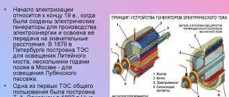
At the dawn of electrification, the DC generator remained the only source of electrical energy. Quite quickly, these alternators were supplanted by more advanced and reliable three-phase alternating current generators. In some industries, direct current continued to be in demand, so devices for its generation were improved and developed.
Even in our time, when powerful rectifier devices have been invented, the relevance of direct current generators has not been lost. For example, they are used to power power lines in urban electric transport used by trams and trolleybuses. Such generators are still used in telecommunications technology as sources of direct current in low-voltage circuits.
Features (device) of generator design
Regardless of the specific type, a generator set consists of two basic components - the engine and the alternator. The engine produces mechanical energy by burning fuel, and the alternator converts it into electrical energy.
DC Generators
. The design of motors of this type includes the following main elements: stator, rotor and winding. The main difference from alternating current generators is the presence of a special half-ring, which allows you to direct the current in one single direction.
Alternators
have an almost identical design, however, the rotor in such motors rotates much faster, the current changes direction from phase to zero and back about 100 times per second. Such generators have less power than DC generators.
Design and principle of operation
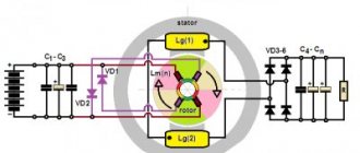
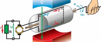
The operation of the generator is based on the principle arising from the law of electromagnetic induction. If a closed circuit is placed between the poles of a permanent magnet, then when rotating it will cross the magnetic flux (see Fig. 1). According to the law of electromagnetic induction, at the moment of intersection, an emf is induced. The electromotive force increases as the conductor approaches the pole of the magnet. If a load R is connected to the collector (two yellow half rings in the figure), then current will flow through the formed electrical circuit.
Rice. 1. Operating principle of a DC generator
As the turns of the frame leave the zone of action of the magnetic flux, the EMF weakens and acquires a zero value at the moment when the frame is positioned horizontally. Continuing the rotation of the circuit, its opposite sides change magnetic polarity: the part of the frame that was under the north pole takes a position above the south magnetic pole.
When the poles change, the direction of the current changes. But due to the fact that the collector rotates synchronously with the frame, the current at the load is always directed in one direction. That is, the model under consideration ensures the generation of constant electricity. The resulting EMF has the form: e = 2Blvsinw t, which means that its change obeys a sinusoidal law.
Strictly speaking, this design only ensures the polarity of the stationary brushes, but does not eliminate EMF pulsation. Therefore, the graph of the generated current looks as shown in Fig. 2.
Figure 2. Graph of the current produced by a primitive generator
Engines and generators.
A standard diesel power plant has an operating principle based on the use of a diesel engine. It is this part that initiates the activation of the system and ensures the completion of its main tasks. The internal combustion engine in such systems most often has an overhead valve device, since this solution is the most compact, quiet, reliable and less toxic than other analogues.
Modern electricity generators are equipped with air and liquid cooling engines. Air ones are more often used in everyday life, while liquid ones are suitable for factory conditions. Also, based on the characteristics of air supply to the internal combustion engine, systems are distinguished with turbocharging, without turbocharging, and also those combined with intercooling and classic turbocharging.
Considering that a diesel power plant is characterized by an operating principle in which the expansion energy of gases becomes mechanical, and that, in turn, electrical, in this system one of the most important places is assigned to the alternator or alternating current generator. It can be either synchronous or asynchronous. This product includes a housing, inside which is a movable rotor that rotates in a stator (core with winding). The rotor can be brushed or brushless, but its task is standard: generating an EM field. Thanks to this effect, an electromotive force appears in the stator windings, producing an output current with the desired characteristics.
Classification
There are two types of DC generators:
To self-excite generators, they use electricity generated by the device itself. Based on the principle of connecting the armature windings, self-excited alternators are divided into types:
Let us consider in more detail the features of each type of connection of armature windings.
With parallel excitation
To ensure normal operation of electrical appliances, a stable voltage is required at the generator terminals, independent of changes in the total load. The problem is solved by adjusting the excitation parameters. In alternators with parallel excitation, the coil leads are connected through a control rheostat in parallel to the armature winding.
Excitation rheostats can short-circuit the winding to themselves. If this is not done, then when the excitation circuit breaks, the self-induction EMF in the winding will sharply increase, which can break through the insulation. In a short circuit condition, energy is dissipated as heat, preventing destruction of the generator.
Electric machines with parallel excitation do not require an external power source. Due to the presence of residual magnetism, which is always present in the core of the electromagnet, self-excitation of parallel windings occurs. To increase residual magnetism in field coils, electromagnet cores are made of cast steel.
The self-excitation process continues until the current reaches its maximum value and the EMF reaches its nominal values at optimal rotation speed of the armature.
Advantage: generators with parallel excitation are weakly affected by short-circuit currents.
With independent excitation
Batteries or other external devices are often used as a power source for field windings. Models of low-power machines use permanent magnets, which ensure the presence of the main magnetic flux.
On the shaft of powerful generators there is an exciter generator that produces direct current to excite the main armature windings. For excitation, 1–3% of the rated armature current is sufficient and does not depend on it. The EMF is changed by a control rheostat.
The advantage of independent excitation is that the excitation current is not affected in any way by the terminal voltage. And this ensures good external characteristics of the alternator.
With sequential excitation
The series windings produce a current equal to the generator current. Since the load is zero at idle, the excitation is zero. This means that the idle speed characteristic cannot be removed, that is, there are no adjustment characteristics.
In generators with series excitation there is practically no current when the rotor rotates at idle speed. To start the excitation process, it is necessary to connect an external load to the generator terminals. This pronounced dependence of voltage on load is a disadvantage of series windings. Such devices can only be used to power electrical appliances with a constant load.
With mixed excitement
Useful characteristics combine the designs of generators with mixed excitation. Their features: the devices have two coils - the main one, connected in parallel to the armature windings, and the auxiliary one, which is connected in series. A rheostat is included in the parallel winding circuit, which is used to regulate the excitation current.
The process of self-excitation of an alternator with mixed excitation is similar to that of a generator with parallel windings (due to the absence of an initial current, the series winding does not participate in self-excitation). The no-load characteristic is the same as that of an alternator with parallel winding. This allows you to regulate the voltage at the generator terminals.
Mixed excitation smoothes out voltage ripple at rated load. This is the main advantage of such alternators over other types of generators. The disadvantage is the complexity of the design, which leads to an increase in the cost of these devices. Such generators do not tolerate short circuits.
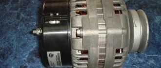
Recommendations for replacement
Operating practice shows that replacing an alternator in a car is not difficult, but the task requires compliance with a number of rules:
- The new device must have the same current values as the factory device.
- The energy values must be identical.
- The gear ratios of the old and new power supplies must be the same.
- The installed unit must be of the appropriate size and easily connect to the engine.
- The alternator circuits for new and old cars should be the same.
Please note that devices installed on foreign-made cars do not have the same mounting as, for example, on the TOYOTA COROLLA and Lada Granta generator.
Therefore, if you replace a foreign unit with a domestic product, you will need to install a new mount.
Application
Until recently, the use of DC traction generators in railway transport had no alternative. However, the process of replacing these generators with synchronous three-phase devices has already begun. The alternating current of the synchronous alternator is rectified using semiconductor rectifier units.
Some Russian locomotives of the new generation already use asynchronous motors operating on alternating current.
A similar situation is observed with car generators. DC alternators are replaced with asynchronous generators, followed by rectification.
Perhaps only mobile welding machines with autonomous power supply are invariably paired with DC alternators. Some industries have also not abandoned the use of powerful DC generators.
Engine functionality systems.
The operating principle of any diesel generator is the cooperation of the internal combustion engine and the alternating current generator. However, if the engine is not in the best condition, this will negatively affect the condition of the entire structure. To ensure the motor maximum productivity and good performance, manufacturers have equipped it with a number of complementary structures:
- cooling (consists of a pump, tank, pipelines; can be water or air, based on the use of various refrigerants);
- starting the engine (starter, starting valve, battery with charging, compressor, pipes; the complex of these elements helps to activate the engine without incident);
- lubricant (consists of oil tanks, filters, radiators, oil lines and pumps; neutralizes the effect of excessive friction of the internal combustion engine with neighboring elements);
- fuel (made using fireboxes, pipelines, pumps; ensures the supply of diesel to the engine for its subsequent processing);
- heating (maintains the thermal parameters of the engine at the proper level, which is especially important for street operation systems; includes elements of both ventilation and heating: coils, heaters, lamps, etc.).