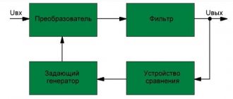
Home > Generators > Blocking generator: operating principle
Devices of this type are used to create signals with high duty cycle that are rarely repeated. They use a transformer, which is included in the feedback circuit. The presence of galvanic isolation at the output allows the formation of high-voltage pulses. This feature is used to power line scanning units and Tesla coils.
What does a blocking generator look like?
A simple generator blocking circuit can be assembled without difficulty at home.
Principle of operation
The diagram shown below will help you understand the functioning of the blocking generator.
Schematic diagram of a typical generator
The following list shows the main stages of work:
- After applying voltage through resistor R1, capacitor C is charged. The completion time of this process is determined by the parameters of these elements.
The amount of current is limited by the resistance of the circuit, and the voltage at the capacitor terminals does not have time to reach its maximum.
- As soon as it reaches a certain value, the transistor will begin to open. The current begins to flow through the circuit: transformer winding – collector – emitter. At this stage, the voltage reaches its maximum almost instantly and the current increases relatively slowly.
- It induces an EMF in the transformer winding connected to the base, which further increases the voltage and opens the transistor. This process ends when the transformer core is saturated (the material is not capable of conducting a magnetic field of a certain intensity). It will also stop when the base current increases, until the saturation threshold of the semiconductor device.
- The transistor turns off. Charging of capacitor C begins. The inductance of the transformer winding produces an emf in the direction opposite to the original one. This speeds up the closing of the transistor.
The principle of operation of a blocking generator is easier to understand with the help of timing diagrams, which illustrate the change in electrical parameters in individual parts of the circuit.
Current and voltage diagrams
These drawings must be studied in conjunction with the following drawing, which shows another circuit diagram of a blocking generator.
Generator blocking circuit
The figure above does not show a specific load (designation Rн). The diode performs damping functions. It prevents voltage surges that could damage the transistor.
The stages described above are clearly visible in the diagrams. Below are the features that are characteristic of the second scheme:
- The combination t0 marks the moment when the voltage at the base of the transistor is not enough to open it.
- The time interval t0 – t1 indicates the period of gradual opening of the transistor. At the end point, saturation has occurred, so changing the base current does not affect the pulse shape.
- However, the capacitor discharge occurs. Therefore, there is a gradual decrease in the base current.
- Since the load on the collector has inductive characteristics, the current Ic does not decrease. The duration of this period is determined by the parameters of the transformer core.
- The pulse cutoff begins at point t2. The current created by induction decreases, which provokes a gradual closing of the transistor switch. The figures show when current appears in the opposite direction. This process intensifies the discharge of the capacitor. The closing speed of the transistor increases, and the cutoff becomes steep (formed in a short time).
- Point t3 indicates the moment the transistor gate is completely closed. After it, the appearance of oscillatory processes is permissible. To block them, a diode is installed in this circuit.
Blocking generator
In this article I will tell you about what a blocking generator is .
A blocking generator is a pulse generator of relatively short duration and long period. It works thanks to transformer feedback. Because of its simplicity, the blocking generator is widely used in compact voltage converters (for example, this circuit can be found in every second electronic lighter circuit).
This is a blocking generator (one of many variations of this scheme):
As you can see, it is really easy to assemble. The most difficult part in it is the transformer. But first things first.
1) Operating principle
First, winding 2 acts as a “resistor”, i.e. a current flows through it and the resistor, which begins to open the transistor. Opening the transistor leads to the appearance of a current in winding 1, and this in turn leads to the appearance of voltage on winding 2, i.e. the voltage at the base of the transistor increases further, it opens even more, and this happens until the core or transistor enters saturation. When this happens, the current through winding 1 begins to decrease, therefore the voltage on winding 2 changes polarity, which leads to the closing of the transistor. That's it, the cycle is closed!
2) Details
Transformer winding 1 is usually 2 times larger than winding 2, and the number of turns and wire diameter are selected depending on the voltage on winding 3 and the current through it.
The resistor is usually taken in the region of 1 kOhm - 4.7 kOhm.
Almost any transistor will do.
3) Test
First, let's assemble a basic generator circuit. This is the transformer from the ballast of an energy-saving lamp:
On it I first wound winding 2 (18 turns with 0.4 mm wire)
I insulated it (ordinary electrical tape will do)
And then I wound winding 1 (36 turns with the same wire as the 2nd one)
And finally, I inserted the core and secured it with the same electrical tape
At this point the transformer is ready.
I chose a powerful transistor: KT805, because the winding has only 36 turns of not the thinnest wire (low resistance).
Resistor 2.2 kOhm.
This is what I ended up with:
As you understand, I will take food from the crown.
So, with a KT805 transistor, a 2.2 kOhm resistor and winding 1 is 2 times larger than winding 2, the voltage oscillogram between the collector and emitter looks like this:
Amplitude 60V, frequency about 170kHz.
Now let's install a 4.7 kOhm resistor. The oscillogram looks like this:
The amplitude is about 10V, the frequency is the same.
Now let's install a 1kOhm resistor:
Amplitude 120V, frequency about 140kHz.
Now let's put back the 2.2 kOhm resistor and swap the windings:
Amplitude 80V, frequency about 250kHz.
4) Conclusion
The greater the feedback coefficient, the faster the signal rises, and the higher the frequency. (The smaller the resistor, and the greater the ratio of the number of turns of winding 2/the number of turns of winding 1, the greater the feedback coefficient). The feedback factor is also affected by the gain of the transistor.
5) Practical benefits
You probably noticed that I didn’t say a word about winding 3. It is needed in order to relieve the output voltage.
Let's see what happens if we wind 3,100 turns of 0.08mm wire into a winding:
First, of course, we need to wind up the transformer. Let's isolate the last layer in the past:
Now we wind 100 turns of 0.08 wire. We assemble the core. WE CONNECT A DIODE TO THE OUTPUT (any one with a reverse voltage of at least 200V can be used. For example, I took the cheap and common 1n4007). Soldering the circuit:
A diode is needed to cut off negative emissions. Let's look at the output oscillogram:
Constant component 50V, pulses amplitude 50V. To remove the pulse component, we place a capacitor at the output. 0.1uF will do:
Oscillogram:
Constant voltage with an amplitude of 100V.
When approaching:
Small fluctuations with an amplitude of 50 mV.
And finally, the complete diagram:
If there is no generation, solder a couple of microfarads capacitor parallel to the resistor.
List of radioelementsDesignation Type Nominal Quantity NoteShopMy notebook
Bipolar transistor KT805A1
Rectifier diode 1N40071
Resistor2.2 kOhm1
Resistor4.7 kOhm1
Resistor1 kOhm1
Capacitor0.1 uF1 Add all
Calculation
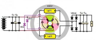
Operating principle of a synchronous generator
The principle of operation of the blocking generator is clear. Below is a calculation that will help you choose the right transistor of the second circuit diagram.
For the example, the following initial parameters were used:
- frequency (F) – 40 kHz;
- duty cycle (C) – 0.25;
- amplitude (AM) – 6 V;
- resistance Rng (load) – 30 Ohm;
- voltage at the output of the power source (PS) – 300 V.
The permissible base-collector voltage should be from 1.5 to 2 times greater than NP. For this example - from 450 to 600 V.
The collector current ( Ik ) is determined by the formula:
Ik must be equal to or greater than ((3...5)*AM*CTF)/ Rng.
KTF is a coefficient that takes into account the features of energy transformation (collector - load windings):
CTF=(1.2*AM) / NP=(1.2*6)/300=0.024.
Thus, the permissible collector current must be greater than the following values:
((3…5)*6*0,024)/ 30 = 0,0144…0,024.
The maximum frequency (Chmax, kHz) is calculated using the following formula:
Hmax≥(5…8) * H = (5…8) * 40 = 200…320.
Based on the data obtained, the type of transistor is determined.
Parameters of a suitable conditional device:
- maximum collector-base voltage (NCV) – 620 V;
- maximum base-emitter voltage (NBE) – 8 V$
- maximum collector current (Ik) – 0.03 A;
- collector-base current (Ikb) – 12 µA;
- maximum frequency (Chmax) – 1000 kHz;
- base resistance (Rb) – 250 Ohm.
Calculation and practice allow you to assemble a blocking generator with your own hands
To create a blocking generator correctly, you need to know theory and practice, and be able to make calculations.
Field-effect transistor generator
The operating principle of this device does not differ from the options discussed above. But changes have been made to the scheme that significantly increase energy efficiency, reliability and durability.
Field-effect transistor generator blocking circuit
Recommendations for proper assembly of the product:
- The domestic transistors and diodes indicated in the drawing can be replaced with similar imported semiconductor devices with suitable electrical characteristics.
- Resistance R2 is selected so that the voltage at C1 in idle mode does not exceed 450 V. This setting will prevent breakdown of the semiconductor junction of the VT transistor
- To avoid damaging the device, it should not be turned on without load.
- Resistance R6 performs protective functions. Its presence allows you to disconnect the generator from the network when the circuit breaker S is open
Device based on field-effect transistor PP20
A blocking oscillator based on a field-effect transistor is considered quite popular today. Such models are most often used in radio receivers. However, they are also suitable for measuring instruments. In this case, the threshold frequency parameter is on average around 80 Hz. Capacitors in such models are often installed in a pass-through type. However, asynchronous modifications are also found on the market.
These blocking generators operate exclusively with sinusoidal signals. In this case, a wide variety of rectifiers are installed. The phase frequency in such devices is changed by changing the voltage in the converters. The conductivity of the device signal depends on the power of the rectifier. To make a blocking generator with your own hands, the power supply is usually set to 20 V. You can even take it from a personal computer.