Piezoelectrics
In fact, quartz is one of the most common minerals in the earth's crust. Its share is about 60%! If semiconductor radio components are mainly made of silicon, then quartz also consists of silicon but combined with oxygen. Its chemical formula is SiO2.
The mineral quartz looks something like this.
mineral quartz
Well, just like some kind of treasure! But the value of this treasure is hidden not in the quartz itself, but in the properties it has. And this quartz effect has revolutionized precision electronics for generating highly stable electrical signal oscillations.
Back in the 19th century, the two Curie brothers discovered the interesting property of some solid crystals to generate emf by deforming these crystals. Deformation is a change in the shape of a body through torsion, impact, stretching, and so on. So, when they hit such crystals, they discovered that they could produce some kind of short-term voltage.
piezoelectric effect
But they also found the opposite effect. When voltage was applied to such crystals, these crystals themselves deformed. It was practically invisible to the naked eye. This effect was called the piezoelectric effect , and the substances were called piezoelectrics .
It should be noted that EMF occurs only during compression or tension. Maybe you thought that you could press such a crystal with some heavy block and receive energy from it all your life? No matter how it is! By the way, a radio element, a piezoelectric emitter, also belongs to piezoelectrics, and EMF can be obtained from it. Below you can see this case in the video. An LED soldered to the piezo emitter lights up when the piezo emitter itself is struck.
Not long ago I watched a film on National Geographic. There, entire piezoelectric plates were installed on the road. People walked on them and generated electrical energy without knowing it). By the way, very free, clean and renewable energy. Okay, I got distracted... So, quartz crystals also have a piezoelectric effect and are also capable of generating EMF or deforming (bending, changing shape) under the influence of electric current.
5.19. Generators with quartz resonators
Active filters and generators
Generators
Subsections: 5.12 5.13 5.14 5.15 5.16 5.19 5.18 5.19
A stability of about 0.1% can easily be achieved from an RC oscillator with an initial frequency setting accuracy of 5 to 10%. This is quite satisfactory for many applications, such as the multiplex indicator of a pocket calculator, where the digits of a multi-digit number are illuminated one after the other in rapid succession (typically 1 kHz). Only one number is lit at a time, but the eye sees the entire number. Clearly, accuracy is not very important here. The stability of LC oscillators is somewhat better - about 0.01% over a reasonable period of time. This is quite enough for local oscillators of radios and televisions.
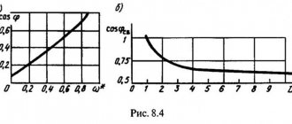
To obtain truly stable oscillations, crystal oscillators are indispensable. They use a piece of quartz (artificial - silicon dioxide) cut and polished so that it has a specific vibration frequency. Quartz is a piezoelectric (its deformation causes an electrical potential to appear, and vice versa), so elastic vibrations of the crystal can be caused by the application of an electric field, and these vibrations in turn generate voltage on the crystal faces. By placing contacts on the surface of the crystal, you can turn it into a true circuit element, equivalent to some RLC circuit pre-tuned to a specific frequency. In fact, the equivalent circuit of this element contains two capacitors that give a pair of closely spaced resonant frequencies - series and parallel resonance (Fig. 5.47), differing from each other by no more than 1%. The result of this effect is a sharp change in reactance with frequency (Fig. 5.48). The high quality factor Q of the quartz resonator (usually about 10000) and good stability make it natural Fig. 5.48. use as a driving element in generators and filters with improved parameters. Crystal oscillator circuits, like LC oscillators, introduce positive feedback and provide proper gain at the resonant frequency, leading to self-oscillation.
Rice. 5.47.
Rice. 5.48.
In Fig. Figure 5.49 shows some circuits of crystal oscillators. In Fig. 5.49, and shows a classic Pierce oscillator, which uses a conventional field-effect transistor (see Chapter 3). In Fig. 5.49, b shows a Colpitts oscillator with a quartz resonator instead of an LC circuit. In the diagram in Fig. 5.49, a combination of a bipolar npn transistor and a quartz resonator is used as feedback. The remaining circuits generate an output signal with logic levels using digital logic functions (Figure 5.49, d and e).
Rice. 5.49. Circuits with quartz resonators, a - Pierce oscillator, b - Colpitts oscillator.
The last diagram shows the crystal oscillator circuits built by Motorola's MC12060/12061 ICs. These ICs are designed for use with quartz crystals in the 100 kHz to 20 MHz frequency range and are designed to provide excellent frequency stability while carefully limiting amplitude using a built-in amplitude discriminator and circuit limiter. They provide the formation of output oscillations of both sinusoidal and rectangular shapes (with TTL and ESL logical levels).
As an alternative, namely in cases where it is sufficient to have only a square wave output and there are no extreme stability requirements, complete crystal oscillator modules can be used, which are usually produced in metal DIP packages. They offer a standard set of frequencies such as 1, 2, 4, 5 6, 8 10 16 and 20 MHz), as well as "strange" frequencies that are commonly used in microprocessor systems (for example, the frequency 14.31818 MHz is used in video cards. These "quartz clock modules" typically provide an accuracy (over a range of temperatures, power supply voltages and time) of only 0.01% (10-4), however they are cheap ($2 to $11) and you don't have to build circuit. In addition, they always produce stable oscillations, whereas when creating your own oscillator this is not always possible to achieve. The functioning of oscillator circuits on quartz rectifiers depends on the electrical properties of the crystal itself (such as series or parallel mode of oscillation, effective series resistance and capacitance installation), which are not always fully known. Very often you may find that although your homemade crystal oscillator is excited, it is at a frequency that does not correspond to that indicated on the crystal oscillator. In our own research in the field of discrete crystal oscillator circuits, anything has happened.
Quartz resonators are available in the range from 10 kHz to 10 MHz, and in some samples high overtones reach up to 250 MHz. Each frequency requires its own resonator, but for the most common frequencies, resonators are mass-produced. It is always easy to obtain resonators for frequencies of 100 kHz, 1, 2, 4, 5 and 10 MHz. A quartz resonator with a frequency of 3.579545 MHz (costing less than a dollar) is used in the color pulse generator of televisions. For electronic wristwatches, a frequency of 32.768 kHz (or 215 Hz) is needed, and in general, frequencies equal to some power of 2 Hz are often needed. The quartz oscillator can be adjusted in a small range using variable capacitors connected in series or parallel (see Fig. 5.49, d). Due to the low cost of quartz resonators, it always makes sense to consider their use in cases where RC relaxation oscillators are operating at the limit of their capabilities.
If necessary, the stable frequency of the quartz oscillator can be “adjusted” electrically within small limits using a varactor. This circuit is called a VOC (voltage controlled crystal oscillator), and it manages to combine the excellent stability of crystal oscillators with the adjustability of LC oscillators. Purchasing a commercial UNCG is probably the best solution to the problems that arise when designing your own. Standard UNCGs provide maximum deviations of the central frequency from the nominal value of the order of ±10-5 - ±10-4, although there are samples with a wider range (up to ±10-3).
Without much effort, a quartz resonator can be used to ensure frequency stability of the order of a few parts per million in the normal temperature range. Using temperature compensation circuits, it is possible to build a temperature-compensated crystal oscillator (TCO) with slightly improved parameters. Both the TKKG and the uncompensated generator are produced as ready-made modules by various companies, for example Biley, CTS Knights, Motorola, Reeves Hoffman, Statek and Vectron. They come in different sizes, sometimes no larger than a DIP housing or a standard housing for TO-5 transistors. Cheap models provide stability of about 10-6 in the range from 0 to 50°C, expensive ones - about 10-7 in the same range.
Temperature compensated generators. To obtain ultra-high stability, a crystal oscillator operating under constant temperature conditions may be needed. Typically, for these purposes, a crystal with a practically zero temperature coefficient at a slightly elevated temperature (from 80° to 90 °C) is used, as well as a thermostat that maintains this temperature. Generators made in this way are produced in the form of small complete modules, suitable for installation and included in devices for all standard frequencies. A typical oscillator module with improved performance is the 10811 from Hewlett-Packard. It provides stability of the order of 10-11 for a period of time from several seconds to several hours at a frequency of 10 MHz.
If temperature instability is reduced to very small values, then other effects begin to dominate: crystal aging (the tendency of frequency to decrease over time), power supply deviations from nominal, and external influences such as shock or vibration (the latter being the most serious problems). in the production of quartz wristwatches). One way to solve the problem of aging: the generator’s data sheet indicates the frequency reduction rate - no more than 5·10-10 per day. The aging effect occurs in part due to the gradual release of deformation, so after a few months from the time of manufacture this effect tends to decline steadily, at least for well-made crystals. The 10811 generator we took as a sample has an aging effect of no more than 10-11 per day.
In cases where the stability of thermostated crystals is no longer sufficient, atomic frequency standards are used. They use microwave absorption lines in a rubidium gas-filled element or the frequencies of atomic transitions in beams of cesium atoms as standards against which a quartz resonator is stabilized. This way you can get accuracy and stability of the order of 10-12. The cesium standard is the official standard of time in the United States. These standards, along with the time lines, are owned by the National Bureau of Standards and the Naval Observatory. As a last resort for the most precise frequencies, where stability of the order of 10-14 is needed, an atomic hydrogen maser can be proposed. Recent research into precision watches has focused on techniques using "cooled ions" to achieve even better stability. Many physicists believe that a final stability of 10-18 can be achieved.
Subsections: 5.12 5.13 5.14 5.15 5.16 5.19 5.18 5.19
Self-explanatory diagrams
Quartz resonator
What is a quartz resonator?
Currently, many types of crystalline substances have been identified, but quartz minerals are most used in electronics, since in addition to being piezoelectric, it also has good mechanical strength.
Resonator - (from the Latin resono - I sound in response, I respond) is a system that is capable of oscillating with maximum amplitude, that is, resonating, when exposed to an external force of a certain frequency and shape. It turns out that a quartz resonator in electronics, or popularly just “quartz,” is a radio element that is capable of resonating if an alternating current of a certain frequency and shape is applied to it.
Quartz resonators look something like this.
types of quartz resonators
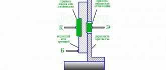
Quartz is a dielectric. What happens if a thin dielectric is placed between two metal plates? You'll get a capacitor! The capacitor turns out to have a very small capacity, so it is unlikely that it will be possible to measure its capacity. But they didn’t bother with the circuit designation of quartz, and on the diagrams it is shown as a rectangular piece of crystal enclosed between two capacitor plates.
designation on the diagram of a quartz resonator
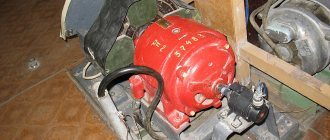
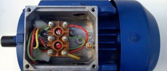
Having disassembled the quartz resonator, we can see with our own eyes the quartz crystal itself. Let's open the Soviet-made quartz in a case like this.
Here we see a transparent quartz crystal placed between two metal plates, to which the leads are soldered.
what's inside a quartz resonator
In small quartzes like these
quartz resonator
thin rectangular quartz plates are used. The physical size and thickness of the quartz plate inside the quartz resonator must be strictly observed, since it is its overall dimensions that affect the main oscillation frequency. The rule here is: the thicker the plate, the lower the operating frequency of the quartz. Therefore, the highest frequencies at which quartz is made is no more than 50 MHz, since the plate is very thin, which creates difficulties in its manufacture. Yes, and you need to somehow keep it in the case without breaking it. In theory, you can squeeze the frequency out of quartz up to 200 MHz, but such quartz will work on an overtone.
Overtones of a quartz resonator
Overtones, or as they are also called, modes or harmonics, are multiple frequencies above the fundamental frequency of quartz. Using filters, the fundamental frequency of quartz is suppressed and the overtone is isolated. odd overtones are used in the overtone mode . If the fundamental frequency of quartz F is the first overtone, then its working overtones will be 3F, 5F, 7F, 9F. It is also worth noting that the amplitude of the overtone decreases with increasing its frequency, therefore, there is no point in taking the 9th overtone, since isolating the amplitude of a small signal is very problematic.
Example: let's take quartz with a frequency of 10 Megahertz. Then we can excite it at overtones of 30 Megahertz (third overtone), 50 Megahertz (fifth overtone), 70 Megahertz (seventh overtone) and a maximum of 90 Megahertz (ninth overtone).
To somehow understand what overtones are, for example, listen to the fundamental frequency of 110 Hertz and its overtones.
The circuit that excites quartz on overtones is complex and not very reliable, since firstly, it is necessary to “press” the main frequency of quartz and release the overtone, and secondly, quartz can be excited in the mode of random oscillations. In practice, they still make circuits that multiply the main frequency of quartz, which is much simpler and more reliable. There is also one more rule here: if the frequency is marked in whole numbers in Kilohertz, this is work on the fundamental harmonic, and if in Megahertz separated by commas, this is an overtone harmonic. For example: RG-05-18000 kHz is a resonator for operating at the fundamental frequency, and RG-05-27.465 MHz is for operating at the 3rd overtone.
Series and parallel quartz resonance
There are a lot of myths circulating on the Internet specifically about the quartz resonator. The most popular myth goes like this: if you apply a constant voltage to a quartz resonator, it will produce an alternating voltage with the frequency indicated on it. I may agree about the “frequency indicated on it,” but alas, about the constant voltage. The quartz crystal will simply shrink or unclench). Some people still think that quartz itself produces alternating current). Yeah, just a perpetual motion machine).
In order to understand the principle of operation of a quartz resonator, it is necessary to consider its equivalent circuit:
equivalent circuit of a quartz resonator
C is the actual capacitance between the plates of the capacitor. That is, if you remove the quartz crystal, you will be left with two plates and their leads. They are the ones who have this capacity.
C1 is the equivalent capacity of the crystal itself. Its value is several femtoFarads. Femto is 10-15!
L1 is the equivalent inductance of the crystal.
R1 – dynamic resistance, when operating quartz it can reach from several Ohms to several KOhms
It can be noted that C1, L1 and R1 form a series oscillatory circuit, which has its own resonant frequency.
series oscillating circuit
The resonant frequency of such a circuit is calculated by the formula
formula for series resonance of a quartz resonator
But everything would be fine, but as you can see, in the equivalent circuit of a quartz resonator there is also one heavy capacitor C, which spoils the whole raspberry.
This whole circuit turns into a complex parallel oscillatory circuit. The resonant frequency of such a circuit will already be determined by the formula
formula for parallel resonance of a quartz resonator
Therefore, remember: each quartz resonator can be excited at two resonant frequencies . At the series resonance and at the parallel resonance . If we see an inscription like this on quartz
quartz frequency
this tells us that the series resonance frequency for this crystal oscillator is 8 MHz. Quartz resonators in electronics operate precisely at the frequency of series resonance. In my practice, I don’t remember anyone exciting quartz to operate at a parallel resonance frequency.
Clock quartz resonator
Most often, watch quartz looks like this.
“What kind of watch quartz is this?” - you ask. Hour quartz is quartz with a frequency of 32,768 Hertz. Why does it have such a strange frequency? The thing is that 32,768 is 215. This quartz works in tandem with a 15-bit counter chip. This is our K176IE5 microcircuit.
The operating principle of this microcircuit is as follows: after it counts 32,768 pulses, it emits a pulse on one of the legs. This pulse on a leg with a quartz resonator at 32,768 Hertz appears exactly once per second . And as you remember, oscillation once per second is 1 Hertz. That is, on this leg the pulse will be issued with a frequency of 1 Hz. And if this is so, then why not use it in watches? This is where the name came from - watch quartz .
Currently, in wristwatches and other mobile gadgets, this counter and quartz resonator are built into one chip and provide not only counting of seconds, but also a number of other functions, such as alarm clock, calendar, etc. Such microcircuits are called RTC (Real Time C lock ) or translated from bourgeois Real Time Clock
.
Operating principle of quartz resonators and generators
The operating principle of quartz resonators is based on the use of the piezoelectric effect.
Some substances and crystals have an asymmetrical structure (acentric crystals). Mechanical forces acting on such crystals cause not only mechanical stress in them, but also electrical polarization. As a result, charges are formed on the surface of the crystal. This effect is called the direct piezoelectric effect, and crystals, accordingly, are piezoelectrics. The most common piezoelectric material is quartz crystals.
There is also an inverse piezoelectric effect: when a piezoelectric is exposed to an electric field, mechanical deformations occur in its structure.
A quartz resonator is a specially sawn, processed and oriented quartz crystal, with external electrodes located on opposite sides. During operation, such a resonator uses both direct and inverse piezoelectric effects; it constantly converts the electric field into mechanical deformations and vice versa. However, from the point of view of the electrical circuit, these mechanical vibrations remain aside, although they play a vital role, since they largely determine the resonant frequency.
Externally, the design of the resonator resembles the design of a capacitor, but the presence of the piezoelectric effect determines some features of its behavior. The nature of the change in conductivity in the frequency range close to resonance turns out to be the same as that of the oscillatory circuit, which makes it possible to use an equivalent equivalent circuit. The equivalent electrical circuit of a quartz resonator contains four elements (Fig. 1). Elements L1, C1, R1 are called dynamic or equivalent inductance, capacitance and resistance, respectively. Capacitance C0 is called parallel capacitance. This scheme explains well the presence of a resonant frequency.
Rice. 1. Equivalent circuit of a quartz resonator
A crystal oscillator is a complex component that contains an oscillator, a crystal resonator and control circuits. The simplest circuit for switching on a quartz oscillator requires only supplying a supply voltage (Fig. 2).
Rice. 2. Connection diagram for a standard quartz oscillator
Generators have a number of important parameters that determine their applicability in certain cases.
Crystal oscillator
What is a generator? A generator is essentially a device that converts one type of energy into another. In electronics, you can often hear the phrase “electrical energy generator, frequency generator, function generator,” etc.
A crystal oscillator is a frequency generator and contains a quartz resonator. Basically, crystal oscillators come in two types:
those that can produce a sine wave signal
and those that produce a square wave signal, which is most often used in digital electronics.
Pierce's scheme
In order to excite quartz at the resonance frequency, we need to assemble a circuit. The simplest circuit for exciting quartz is a classic Pierce oscillator , which consists of just one field-effect transistor and a small circuit of four radio elements:
pierce circuit for a quartz resonator
A few words about how the scheme works. There is positive feedback in the circuit and self-oscillations begin to appear in it. But what is positive feedback?
At school, all of you were vaccinated for the Mantoux test to determine if you had a tube or not. After some time, nurses came and used a ruler to measure your skin reaction to this vaccination.
When this vaccination was given, it was forbidden to scratch the injection site. But I, then still a new guy, didn’t give a damn. As soon as I began to quietly scratch the injection site, I wanted to scratch even more)) And so the speed of the hand that was scratching the vaccine froze at some peak, because I could oscillate my hand at a maximum frequency of 15 Hertz. Vaccination my arms swelled up to the floor)) And even once they took me to donate blood on suspicion of tuberculosis, but as it turned out, they didn’t find it. It's not surprising ;-).
So why am I telling you jokes from life here? The fact is that this scabies vaccination is the most positive feedback there is. That is, as long as I didn’t touch it, I didn’t want to scratch it. But as soon as I scratched it quietly, it began to itch more and I began to scratch more, and it began to itch even more, and so on. If there were no physical restrictions on my arm, then for sure the vaccination site would have already been worn down to the flesh. But I could only wave my hand with a certain maximum frequency. So, the same principle applies to a quartz oscillator ;-). Give a little impulse, and it starts to accelerate and stops only at the parallel resonance frequency ;-). Let’s call it “physical limitation”.
First of all, we need to select an inductor. I took a toroidal core and wound several turns from MGTF wire
toroidal inductor
The whole process was controlled using an LC meter, achieving a nominal value as in the diagram - 2.5 mH. If it wasn’t enough, he added more turns; if he overdid it, then he decreased it. As a result, I achieved this inductance.
inductance measurement
I didn’t find the transistor in my stash, and the local radio store didn’t have it either. Therefore, I had to order from Ali. If anyone is interested, I got it here.
Its correct name is a field-effect transistor with an N-type channel.
transistor 2n5485 Pinout from left to right: Drain – Source – Gate
Well, then it’s a matter of little things. Let's assemble the circuit:
A small lyrical digression.
As you can see, I tried to reduce connections between radio elements as much as possible. The point is that all radioelements have their own parasitic parameters. The longer their leads are, as well as the wires connecting these radio elements in the circuit, the worse the circuit will work, or even not work at all. And in general, circuits with a quartz resonator on printed circuit boards are traced for a reason. There are subtle nuances here. The smallest parasitic parameters can spoil the entire signal at the output of such a generator.
So, we have assembled the quartz oscillator, applied the voltage, all that remains is to remove the signal from the output of our homemade generator. The OWON SDS6062 digital oscilloscope gets down to business
First of all, I took the quartz to the highest frequency that I have: 32,768 Megahertz. Do not confuse it with watch quartz (which will be discussed below).
No, but what did you want? Did you want to see an ideal sine wave? Not so. The parasitic parameters of the poorly assembled circuit and installation had an effect.
At the bottom left corner the oscilloscope shows us the frequency:
As you can see 32.77 Megahertz. The main thing is that our quartz is alive and the circuit works!
Let's take a 27 MHz crystal.
The frequency was also shown more or less correctly.
Well, we check all the other quartz that I have in the same way.
Here is an oscillogram of quartz at 16 MHz.
The oscilloscope showed a frequency of exactly 16 MHz.
Here I installed quartz at 6 MHz.
Exactly 6 MHz!
At 4 MHz.
All OK.
Well, let’s take another Soviet one at 1 Megahertz. This is what he looks like.
At the top it says 1000 KHz = 1 MHz.
Let's look at the oscillogram.
Worker!
If you really want, you can even measure the frequency with a Chinese generator-frequency meter.
frequency measurement with a frequency meter
400 Hertz error is not very much for an old Soviet quartz, although the problem may not even be with the quartz, but with the frequency meter itself.
Pierce circuit for square wave
So, let's return to Peirce's scheme. The previous Pierce circuit generates a sinusoidal signal
But there is also a modified Pierce circuit for a square wave
And here she is:
Peirce's scheme for a meander
The values of some radioelements can be changed in a fairly wide range. For example, capacitors C1 and C2 can be in the range from 10 to 100 pF. The rule here is this: the lower the quartz frequency, the smaller the capacitance of the capacitor should be. For watch crystals, capacitors can be supplied with a nominal value of 15-18 pF. If the quartz has a frequency of 1 to 10 Megahertz, then you can set it to 22-56 pF. If you don’t want to bother, then just install capacitors with a capacity of 22 pF. You really can't go wrong.
Also a small tip to note: by changing the value of capacitor C1, you can adjust the resonance frequency within very fine limits.
Resistor R1 can be changed from 1 to 20 MOhm, and R2 from zero to 100 kOhm. There is also a rule here: the lower the quartz frequency, the greater the value of these resistors and vice versa.
The maximum crystal frequency that can be inserted into the circuit depends on the speed of the CMOS inverter. I took the 74HC04 chip. It's not very fast-acting. It consists of six inverters, but we will only use one inverter.
Here is its pinout:
Having connected a clock quartz to this circuit, the oscilloscope produced the following oscillogram:
Well, as always, the whole picture was spoiled by parasitic editing parameters. But, pay attention to the frequency. The oscilloscope showed it almost correctly with a small error. Well, this is understandable, since the main function of an oscilloscope is to display the signal, and not to count the frequency)
By the way, does this part of the diagram remind you of anything?
Isn't this part of the circuit used to clock microcontrollers?
She's the one! It’s just that the missing elements of the circuit are already in the MK itself 
Colpitts scheme
This is also a fairly common and famous scheme.
Colpitts circuit
Take as a basis an amplifier circuit with a common collector (emitter follower). Everything is as usual here. Resistors R1 and R2 set the operating point for the transistor. Resistor RE sets the output voltage level. The NPN 2N4265 transistor can operate at frequencies up to 100 MHz, which is why we took it. This circuit will work with crystals in the range from 1 to 5 MHz.
Ready-made crystal oscillator modules
Currently, quartz oscillators are produced in the form of complete modules. Some companies producing such generators achieve frequency stability of up to 10-11 from the nominal value! The finished modules look something like this:
types of crystal oscillators
or so
Such crystal oscillator modules mainly have 4 outputs. Here is the pinout of a square crystal oscillator:
crystal oscillator pinout
Let's check one of them. It says 1 MHz
1 MHz crystal oscillator
Here's his rear view.
By applying a constant voltage from 3.3 to 5 Volts with a plus of 8 and a minus of 4, from output 5 I got a clean, smooth, beautiful square wave with a frequency written on a quartz oscillator, that is, 1 Megahertz, with very small emissions.
signal from a crystal oscillator
Well, you can really admire it).
And the Chinese generator-frequency meter showed the exact frequency.
From here we conclude: it is better to buy a ready-made quartz oscillator than to waste a lot of time and nerves on setting up a Pierce or Colpitts circuit. Pierce's circuit will be suitable for testing resonators and for your various homemade products, although on Aliexpress I came across a ready-made quartz resonator tester capable of measuring quartz frequencies from 1 to 50 MHz. You can look at this link.
Advantages of crystal oscillators
The advantages of quartz frequency oscillators are their high frequency stability. Basically it is 10-5 - 10-6 of the nominal value or, as they often say, ppm (from the English parts per million)
- parts per million, that is, one millionth or the number 10-6. The frequency deviation in one direction or another in a quartz oscillator is mainly associated with changes in ambient temperature, as well as with the aging of quartz. As quartz ages, the frequency of the quartz oscillator becomes a little less every year by about 1.8x10⁻⁷ from the nominal value. If, say, I took quartz with a frequency of 10 Megahertz (10,000,000 Hertz) and put it in the circuit, then over the course of a year its frequency will go down by about 2 Hertz. I think that’s quite tolerable.
A large selection of quartz resonators is here.
Watch a detailed video about a quartz resonator:
Quartz resonators. Types and application. Design and operation
Modern digital equipment requires high precision, so digital devices often contain a quartz resonator, which is a stable and reliable generator of harmonic oscillations. Digital microcontrollers operate based on this constant frequency and use it to operate the digital device. Quartz resonators are a reliable replacement for an oscillation circuit assembled on a capacitor and inductor.
The quality factor of the oscillation circuit based on the coil and capacitor does not exceed 300. It is a characteristic of the oscillation circuit that determines the value of the resonance band. The quality factor shows how many times the energy of the oscillatory system exceeds the energy loss during one oscillation period. The higher the quality factor, the less energy is lost in one period, and the slower the oscillations decay. The capacitance of a capacitor in a conventional circuit fluctuates depending on the temperature of the environment. The magnitude of the inductance of the coil also depends on many factors. There are even corresponding coefficients that determine the dependence of the parameters of these elements on temperature.
Quartz resonators, in contrast to the oscillation circuits described above, have a very high quality factor, reaching several million. At the same time, temperatures within -40 +70 degrees do not affect this parameter in any way. The high stability of quartz resonators at any temperature has led to their widespread use in digital electronics and radio engineering.
Varieties
By body type:
- For volumetric installation (cylindrical and standard).
- For surface mounting.
Based on body material:
- Metal.
- Glass.
- Plastic.
According to the body shape:
- Round.
- Rectangular.
- Cylindrical.
- Flat.
By the number of resonant systems:
- Single.
- Double.
For case protection:
- Sealed.
- Unsealed.
- Vacuum.
By purpose:
- Filter.
- Generating.
An important property of quartz resonators for successful operation is their activity. But it is not determined only by its own properties. The entire electrical circuit affects its activity.
The resonators used in filters use the same types of oscillations as in generator resonators. The filters use 2 and 4 electrode vacuum resonators. For multi-section filters, 4-electrode filters are most often used, as they are more economical.
Operating principle and device
Quartz resonators operate based on the piezoelectric effect formed on a quartz plate. Quartz is a natural crystal. It is a modification of a silicon-oxygen compound, and has the chemical formula Si O2. The mass fraction of quartz in the earth's crust is about 60%, in free form 12%. Other minerals may also contain quartz.
Low-temperature quartz is used to produce quartz resonators. It has a pronounced piezoelectric effect. The chemical stability of quartz is very high; only hydrofluoric acid can dissolve quartz. In terms of hardness, quartz ranks second after diamond. A quartz plate for a resonator is made by cutting a piece of quartz at a given specific angle. Depending on this cut angle, the quartz plate differs in different electromechanical parameters.
The presence or absence of parasitic frequencies, stability of operation at any temperature, and oscillation frequency depend on the type of cut. A layer of one of the expensive metals is applied to both sides of the quartz plate: silver, platinum, nickel or even gold. After this, the plate is fixed with strong wires in the resonator body. Then the housing is hermetically assembled.
As a result, an oscillatory circuit is formed, which has its own resonance frequency, which determines the operation of the entire resonator. If an alternating voltage with a resonance frequency is applied to the electrodes of the plate, a resonance effect will occur, and the amplitude of the plate’s vibrations will increase significantly. In this case, the resonator will reduce its resistance by a significant amount. This process is similar to the process that occurs in a series oscillation circuit (based on a coil and a capacitor). Energy losses when exciting a quartz resonator at the resonance frequency are very small, since the quality factor of the quartz oscillation circuit is very high.
This equivalent circuit consists of:
- R – Resistance.
- C1 – Capacity.
- L – Inductance.
- C2 – Static electric capacitance of the plates together with the holders.
These elements determine the electromechanical parameters of the quartz plate. If the mounting elements are removed, a series circuit LC . When installed on a circuit board, the quartz resonator does not tolerate excessive heat, since its design is very fragile. Strong heating can deform the holder and electrodes, which affects the functioning of the finished quartz resonator. Quartz completely loses its piezoelectric properties when heated to a temperature of 5370 degrees. However, the soldering iron is not capable of heating up that much.
On electrical diagrams, a quartz resonator is designated by analogy with a capacitor, but between the plates there is a rectangle symbolizing a quartz plate. In the diagram the resonator is designated “ QX ”.
Typically, the cause of a malfunction of a quartz resonator is a strong blow or fall of the device in which it is located. In this case, the resonator must be replaced with a new one with the same parameters. Such malfunctions occur in small devices that are easier to drop or damage. But such damage to resonators is not common, and usually the malfunction of the device lies in something completely different.
How to test quartz resonators
To check the resonator for its functionality, a special simple tester is assembled, which helps to check, in addition to the operation of the resonator, also its resonance frequency. The circuit of such a device is similar to a quartz oscillator assembled on a transistor.
By connecting the resonator between the negative pole and the base of the transistor through a protective capacitor, the resonance frequency is measured using a frequency meter. This circuit is suitable for tuning oscillation circuits. When the circuit is turned on, a working resonator creates oscillations. As a result, an alternating voltage appears at the emitter of the transistor with the resonance frequency of the resonator being tested.
If you connect a frequency meter to the output of the tester, you can measure the resonance frequency. With a stable frequency and slight heating of the resonator body with a soldering iron, the frequency should not change significantly. If the frequency meter does not detect the occurrence of a frequency, or it changes greatly or differs greatly from the nominal value, then the resonator is unusable and requires replacement.
When using such a tester to configure circuits, capacitance C1 is required. But when checking the serviceability of resonators, its presence in the circuit is not required. In this case, the oscillatory circuit is simply connected in place of the quartz resonator and the tester begins to create oscillations in the same way.
Electrical parameters
Equivalent circuit of a quartz resonator is an electrical description of a quartz resonator operating at a resonant frequency. The equivalent circuit of a quartz resonator is shown in Figure 1. C0 is the shunt capacitance. R1, L1 and C1 are dynamic resistance, dynamic inductance and dynamic capacitance, respectively. The dynamic parameters are the corresponding equivalents of the resonator as an electromechanical system and are determined mainly by the cutoff characteristics of the quartz element.
It will be interesting➡ Chokes in electrics: what are they and where are they used?
Shunt capacitance C0 – Capacitance between the terminals of the crystal. It is measured in picofarads. The shunt capacitance consists of the parasitic capacitance of the quartz, the capacitance of the crystal electrode region, and the capacitance contributed by the crystal holder. The shunt capacitance has a value of the order of units of pF. Dynamic resistance R1 – Parameter characterizing energy losses in the oscillatory circuit. The dynamic resistance R1 of quartz resonators varies in the range from several Ohms to hundreds of kOhms, depending on the resonance frequency, harmonic number and a number of design factors.
Set of quartz resonators.