Operation and principle of the device
To understand what voltage-increasing transformers are, you need to understand the principle of operation. The equipment is manufactured for power plants whose design schemes belong to the pass-through category.
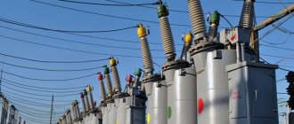
A step-up transformer at power plants is used to provide populated areas and other objects with current with certain technical indicators. Without a converter, the high voltage gradually decreases along its path.
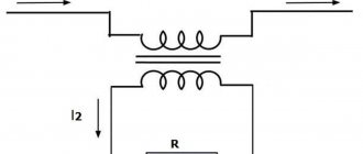
Scheme and principle of operation of a step-up transformer.
The end consumer would receive insufficient electricity. At the final power plant in the circuit, thanks to this installation, electricity of the appropriate value is received. The consumer receives a network voltage of up to 220 V. Industrial networks are provided with up to 380 V.
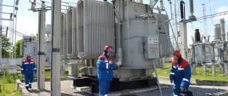
A diagram showing the operation of a transformer in a line includes several elements. The generator at the power plant produces 12 kV electricity. It is supplied through wires to step-up substations. A transformer apparatus is installed here, designed to increase the indicator in the line to 400 kV.
From the substation, electricity enters the high-voltage line. Next, the energy enters the step-down substation. Here it drops to 12 kV. Transformers with a reverse operating principle direct the current to the low-voltage transmission line. At the end, another step-down unit is installed. From it, electricity with an indicator of 220 V is supplied to houses and apartments.
The principle of operation of a transformer network.
When considering how a voltage-increasing transformer works, you need to delve into the basic principles of the design. The basis for the operation of a transformer is the mechanism of electromagnetic induction.
How does a step-up transformer design work?
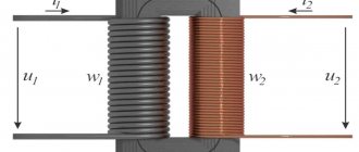
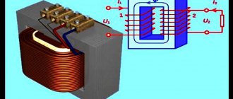
The metal core is in an insulating environment. The circuit includes two coils. The number of windings is not the same. Coils with more turns in the first circuit than in the second can increase the indicator.
AC voltage is supplied to the primary circuit. For example, this is a current in the network of 110 (100) V. A magnetic field appears. Its strength increases with the correct ratio of windings in the core. When electricity passes through the second winding in the step-up transformer, a current with a certain indicator appears. For example, an indicator of the characteristics of a 220 V network is provided.
In this case, the frequency remains the same. To supply direct current to the power supply line, a converter is installed in the circuit. This device can be used in boost-type equipment. The device is capable of working not only to change voltage, but also frequency. Certain equipment is powered by direct current.
Functions and operation of transformers
In electronics, transformers are indispensable devices. However, for them to work most effectively, it is necessary to have a good understanding of what the transformer is stepping down or stepping up. Depending on the needs, they increase or, conversely, decrease the potential in circuits with alternating current.
With the advent of different transformer devices, it became possible to deliver electricity over significant distances. Losses on power line wires are noticeably reduced when the alternating voltage increases and the current decreases. This occurs along the entire length of the conductors connecting the power plant with connected consumers. At each end of such lines, the voltages are reduced to a safe level, facilitating the operation of the equipment used.
Which transformer is called step-up and which is called step-down, and what is the difference between them?
The short answer is that a device that produces a higher potential, compared to the input, is considered a booster. If the reverse process occurs, and the potential at the output is less than at the input, such a device will be a step-down device. In the first case, the secondary winding has a larger number of turns than the primary, and in the second, on the contrary, a secondary winding with fewer turns is used. This is how they differ radically from each other.
Can a step-down transformer be used as a step-up transformer?
Yes, you can. Since to change the functions it is enough to change the connection diagram of the windings with the potential source and the load. Accordingly, the functionality of the step-down transformer will change.
In practice, in order to improve the efficiency of the device, the inductance of all windings is calculated for the exact operating values of current and voltage. These indicators must be maintained in their original state when the step-up and step-down transformer change their functions to the opposite.
How to determine which winding belongs to one or another
Structurally, transformers are made according to such a principle that it is impossible to immediately determine their differences, that is, which wires are called and actually are the primary, and which of them are the secondary winding. Therefore, to avoid confusion, markings are used. The symbol “H” is provided for the high-voltage winding; in step-down devices it serves as the primary winding, and in step-up devices it serves as the secondary winding. Low voltage windings are marked with an “X”.
In order to understand the features, differences and operating principle of each of these devices, they should be considered in more detail.
We assemble with our own hands
A do-it-yourself converter can be a solution to some problems. For example, if for garage work you need to connect equipment with a 220 V power supply, but the network has a voltage of only 36 V, then a self-assembled step-up transformer will solve this problem.
Interesting material for review: useful information about current transformers.
Types of converters 12 to 220 volts
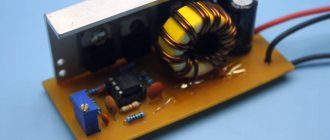
Inverters are devices that allow you to convert direct current values, including 12 V, into alternating current with or without changing the voltage level. Current DC voltage converters currently produced can be represented by:
- voltage regulators;
- voltage level converters;
- linear stabilizers.
It will be interesting➡ How to make a microphone from a phone with your own hands
As a rule, such devices are generators of periodic voltage close to the shape of a sinusoid.
Converter circuit 12 to 220 volts.
Interesting material on the topic: how to assemble a Tesla coil yourself.
Repair and service
A transformer is a complex piece of equipment. Periodic maintenance and repair will be required. It is recommended to entrust this work to professionals. Only a person with appropriate training has the right to carry out such work.
With an increased heating rate and the presence of noise, it is necessary to rewind the transformer circuits. This procedure can only be performed by an unqualified specialist with a minimum level of knowledge in the field of electrical engineering.
The device has a magnetic drive. It is common to coils. The first circuit is responsible for reducing, and the second circuit is responsible for increasing electricity in the network. Inspection of the transformer is carried out using a certain technology.
Examination
First, a visual inspection of the block is carried out. If overheating is observed during operation, deformations, irregularities, and swelling of the insulation appear on the surface. If the inspection does not reveal any deviations, you need to find the input and output of the device. The first of them is connected to the first coil. This is where a magnetic field appears when electricity is supplied. The output is connected to the secondary winding.
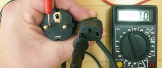
The output signal is filtered. This indicator needs to be measured. The collapsible parts of the housing structure are removed. You need to gain access to the microcircuits. This will allow you to measure the voltage with a multimeter. In this case, you will need to take into account the nominal indicators. If the measurement result is less than 80% of the value specified by the manufacturer, the primary circuit is not functioning correctly.
The first coil is disconnected from the device. It no longer receives electricity. Then the secondary circuit is checked. If there is no filtering, power from the measuring device is used. If there is no normal voltage in the system, the equipment requires repair.
After checking, if the component elements are in good condition, the structure is assembled in the reverse order. If necessary, the unit is repaired.
How to make it yourself
Step-up or step-down transformers are used to convert voltage from low to high levels and vice versa. They are electrical machines with high efficiency and are used in many fields of technology.
You can make a transformer with your own hands at home. In order to correctly assemble a step-up transformer, you must accurately follow the entire technological process and recommendations for assembling this type of electrical machine, which will be given below.
Here you can read about the design of a power transformer and its scope of application.
What you need for self-assembly
First of all, we determine the power of the primary winding of the future converter. To do this, you need to find out the power of the device that we will connect. Typically, this data is indicated in the device passport. For example, let's take an average value of 100 W. It should be taken into account that some reserve will be required, because... the efficiency will be approximately 0.8 -0.9. A power of 150 W is suitable for us. To independently wind a transformer, you need answers to the following questions:
- What is a transformer used for: to increase or decrease voltage?
- What voltages should be at the input and output of the device?
- Does the device operate on 50 Hz AC power or should it be designed for a different frequency?
- What will be the power of a homemade transformer?
Homemade step-up transformer.
After receiving the answers, you can begin purchasing the necessary materials. To do this, buy tape insulation (lacquer cloth) for the future transformer, a core for it (if you have one suitable for the power from an old, burnt-out TV, you can use that too), and the required amount of wire in enamel insulation. Materials and tools used:
- transformer iron core;
- insulation (varnished fabric);
- the wire;
- thin cardboard;
- boards and wooden blocks;
- steel bar;
- glue;
- saw;
- scissors;
- voltmeter.
You need a suitable magnetic circuit. If you do not resort to the services of specialized stores, you can take an “O” shaped core from, for example, an old TV. But you will have to calculate the cross section using the formula: A1= C*C/1.44, where A1 is the power of the future converter (W), and C is the cross section (sq. cm). For us, C should be equal to 10.2 square meters. cm.
We cut out two frames for the magnetic core. We take half of the primary winding and place it tightly on the frames. After installation, insulate with fiberglass. We take half of the secondary winding, also lay it out and insulate it.
We assemble the magnetic circuit and tighten its individual parts with a clamp. We recommend gluing the parts of the device with a special glue containing ferro-powder, then the equipment will not make unnecessary sounds during operation.
To wind windings, you can make a simple winding machine. To do this, take a board 40 cm long and 100 mm wide. Two bars of 50 x 50 millimeters are attached to it with screws so that the distance between them is 30 cm. They must be drilled at the same height with a drill with a diameter of 8 mm. A rod is inserted into these holes, onto which the coil of the future transformer is first placed.
On the one hand, a thread should be cut to a length of 3 cm on the pin and a handle should be attached to it using two nuts, which is used to rotate the rod with the coil when winding the transformer.
The dimensions of the winding machine described above are not critical - it all depends on the size of the core. If it is made of ferroalloys and has the shape of a ring, then the winding will have to be done manually. The process of assembling a step-up transformer is clearly shown in the video.
It will be interesting➡ Connecting a fiber optic cable at home
Calculation of the number of turns
We determine the number of turns per 1 V. We calculate using the formula: K = 50/C, for us it is 50/10.2, i.e. 4.9 turns per 1 V. Afterwards we can easily calculate the number of revolutions of the primary and secondary windings. In the first case, we multiply the available network supply voltage by 4.9, we get 176 turns. In the second, we multiply the required voltage (220 V) by 4.9, we get 1078.
A preliminary calculation of the number of turns can be made based on the required power of the device. For example, if you need a step-up transformer from 12 to 220 V, then the required power of such a device will be in the range of 90-150 W. We choose an O-shaped type of magnetic circuit from an old TV or buy a similar one in the store. Its cross-section should be selected according to the formula from the electrical reference book. In this example it is approximately 10-11 cm².
Design of a homemade transformer.
The next step is to determine the number of turns per 1 V, which in this case is equal to 50 Hz divided by 10-11, something around 4.7-5 units per volt. Now you can calculate the number of turns of the primary and secondary windings: W1= 12 X 5 = 60 and W2= 220 X 5=1100.
Then we need to determine the currents in them: I1 = 150:12 = 12.5 A and I2 = 150:220 = 0.7 A. Let's find the cross-sections and diameters of the winding wires using the formulas from the reference book. The step-up transformer is pre-calculated, you can start winding it.
The next step is to calculate the current of each coil. For the initial indicators we take a power equal to 150 W. Then the primary winding requires a current of 4.2 A, the secondary - 0.7 A. The operating indicator is equal to the power divided by the voltage.
For proper operation of the device, it is important not only the number of revolutions, but also the diameter of the windings. We calculate this parameter using the formula: operating current of the winding, multiplied by a factor of 0.8.
It is worth considering that only a device assembled by professionals can solve industrial and production problems. Using a homemade device is not always safe! Be careful.
Specifications
The main characteristics when operating a transformer are:
- Input voltage.
- Output voltage value.
- Device power.
- Open circuit current and voltage.
The ratio of voltages at the input and output of a device is called the transformation ratio. This ratio depends only on the number of turns in the windings and remains unchanged in any operating mode of the device.
The power of the transformer directly depends on the diameter of the wires and the type of core, which on the side of the primary winding is equal to the sum of the powers of the secondary windings, excluding losses.
The voltage obtained at the output winding of the device, without connecting a load, is called open-circuit voltage. The difference between this indicator and the load voltage indicates the amount of loss due to the different resistance of the winding wires.
The value of the no-load current completely depends on the quality indicators of the transformer core . In an ideal case, the current of the primary winding creates a magnetic field of variable value in the core of the device, the electromotive force of which is equal in magnitude to the no-load current and opposite in direction. But in reality, the magnitude of the electromotive force is always less than the input voltage, due to possible losses in the core.
That is why, in order to reduce the value of the no-load current, high-quality material is required in the manufacture of the core and a minimum gap between its plates. Toroidal cores are more suitable for such conditions.
Manufacturing workflow of coil frames
Transformer coil.
When using a round core, it is first wrapped with tape insulation and then the wire begins to be wound directly onto it, distributing the required number of turns throughout the entire ring.
After the winding of the primary winding is completed, it is covered with 3-4 layers of varnished cloth and then the turns of its secondary part begin to be wound on top. When using conventional magnetic cores, the coil frame is made as follows:
- a sleeve pattern is made with cuffs on the sides of the ends;
- cheeks are cut out of cardboard;
- roll the coil body along the marked lines into a small box and seal it;
- put the upper parts (cheeks) on the sleeve and, bending the flaps, glue it.
After this, the wire is covered with tape insulation, having previously brought the ends of the windings out.
Manufacturing of windings
The coil is placed on a wooden block with the dimensions of the magnetic core. A hole for the winding rod is pre-drilled in it. This part is inserted into the machine, and the winding manufacturing process begins:
- 2 layers of varnished fabric are wound on the reel;
- one end of the wire is fixed on the cheek and the handle of the machine begins to slowly rotate;
- the coils must be laid tightly, isolating each wound layer from the adjacent one with varnished cloth;
- after the primary winding coil is wound, the wire is cut and its second end is fixed on the cheek next to the first.
Insulating tubes are put on both terminals, and the outside of the winding is covered with insulation. The secondary winding coil is wound in the same sequence.
Parameter calculations
On a simple transformer the primary winding has 440 turns for 220 volts. It turns out 1 volt for every two turns. Formula for counting turns by voltage:
It will be interesting➡ How to make a flashing LED?
N = 40-60 / S, where S is the cross-sectional area of the core in cm2. The constant 40-60 depends on the quality of the core metal. Let's make a calculation for installing the windings on the magnetic circuit. In our case, the transformer has a window 53 mm in height and 19 mm in width. The frame will be textolite. Two cheeks at the bottom and top 53 - 1.5 x 2 = 50 mm, frame 19 - 1.5 = 17.5 mm, window size 50 x 17.5 mm.
- The winding of a simple high voltage transformer is 2.18 x 450 = 981 turns.
- Low voltage for filament 2.18 x 5 = 11 turns.
- Low voltage filament 2.18 x 6.3 = 14 turns.
We calculate the required diameter of the wires. The power of the transformer core with your own hands is 170 watts in size. On the network winding the current is 170 / 220 = 0.78 amperes. Current density is 2 amperes per mm2, standard wire diameter according to the table is 0.72 mm. The factory winding is made of 0.5 wire, the factory saved money on this.
The assembled magnetic core, together with the components and connecting elements, forms the core of the transformer. The part on which the windings are wound is the rod. The area of the system intended to complete the circuit and not carrying any turns of the circuit is called the yoke. The arrangement of the rods in space serves to divide the system into the following types.
Types of arrangement of rods.
Number of turns of the primary winding
We take a wire of 0.35 mm, 50 / 0.39 x 0.9 = 115 turns per layer. Number of layers 981 / 115 = 8.5. It is not recommended to draw conclusions from the middle of the layer to ensure reliability. Let's calculate the height of the frame with windings.
Primary of eight layers with 0.74 mm wire, 0.1 mm insulation: 8 x (0.74 + 0.1) = 6.7 mm. It is better to shield the high-voltage winding from other windings to prevent high-frequency interference. In order to wind the transformer, we make a screen winding from one layer of 0.28 mm wire with two layers of insulation on each side: 0.1 x 2 + 0.28 = 0.1 x 2 = 0.32 mm.
The process of winding a transformer coil.
The primary winding will take up space: 0.1 x 2 + 6.7 + 0.32 = 7.22 mm. Step-up winding of 17 layers, thickness 0.39, insulation 0.1 mm: 17 x (0.39 + 0.1) = 6.8 mm. On top of the winding we make layers of insulation 0.1 mm. It turns out: 6.8 + 2 x 0.1 = 7 mm. Height of the windings together: 7.22 + 7 = 14.22 mm. 3 mm left for filament windings.
You can calculate the internal resistance of the windings. To do this, the length of the turn is calculated, the length of the wire in the winding is taken, the resistance is determined, knowing the resistivity from the table for copper.
When calculating the resistance of the primary winding section, a difference of about 6 ohms is obtained. This resistance will give a voltage drop of 0.84 volts at a nominal current of 140 milliamps. To compensate for this voltage drop, we add two turns. Now during loading the sections are equal in voltage.
Step-up voltage transformers
Voltage transformation is present everywhere in every area of our lives and activities.
The voltage generated at the power plant is increased to several kilovolts in order to be transmitted with minimal losses through power lines over many thousands of kilometers. And then it is again reduced at transformer substations to our usual values of 380/220 volts. Step-up transformers are not used to stabilize voltage in cases where its value in the network is constantly changing. For home use, only stabilizers are used.
Let's look at the principle of operation of a voltage transformer in more detail, without plunging into unnecessary complications.
