Description and principle of operation
Current transformer is an electromagnetic converting device, structurally consisting of:
- one-piece magnetic circuit;
- two windings, necessarily isolated from each other and from the ground (primary and secondary);
- plastic sealed non-separable case;
- contact terminals for connecting a measuring device;
- fastening elements for mounting the device;
- plate on the case, paper passport.
The windings of the converter are divided among themselves into primary and secondary, and are included in the energy circuit strictly according to certain rules.
The primary winding is connected to the electrical circuit in series (cutting the conductor). The secondary winding is closed to a certain load of measuring elements, relay equipment and automation. It passes through itself an amount of current that is proportional to the current value of the primary winding.
The operating principle of any of them is based on the law of electromagnetic induction, which operates equally in the electric and magnetic fields of electrical machines and mechanisms.
Its essence is the conversion of the amount of current flowing through the power circuit of the power plant, to which the primary winding of a current transformer with a certain number of turns is connected, into a secondary reduced current value, while maintaining the proportionality of the value.
This proportional amount of electric current at the output terminals of the secondary winding of the transformer is necessary for the normal operation of measuring, relay equipment, and electricity metering devices in power energy systems up to and above 1000 volts.
There is a direct dependence of the nominal operation of all measuring systems, monitoring and control devices on the correct choice of current transformers.
Basic concepts about transformers
The main purpose of the transformer (T) is to convert alternating voltage (U) to the required ratings. T is widely used as the simplest converter of alternating current U, although it is also possible to convert direct current, but this method is economically unprofitable. T operates only from variable U, and this is due to the principle of its operation.
Transformer (T) is a converter of alternating input U into the required rating or ratings for powering consumers. Most consumers are powered by direct current, which is obtained by converting alternating U into direct current using a diode bridge or some other rectifier. This variable U converter is primitive in its design, but there are some design features.
T consists of a magnetic core and coils on which an insulated copper wire is wound. The magnetic core is made of special steel, which has ferromagnetic properties and is called ferromagnetic. The main difference between ferromagnets and ordinary steel is the presence of atoms with constant spin and orbital moments (CSOM). The SIOMs depend on temperature and magnetic field, and thanks to this, the T windings do not overheat during operation due to the absence of Foucault currents. Special transformer steel with ferromagnetic properties reduces the formation of Foucault currents to a minimum, which is not enough to overheat the windings.
The most common materials for the manufacture of magnetic cores are electrical transformer steel (ETS) and permalloy. ETS differs from ordinary steel in its physical and chemical properties, since it contains a significant mass fraction of silicon (Si), which, using special technologies provided at the manufacturer’s plant, combines with carbon under the influence of high temperature and pressure.
This technology for manufacturing ETS has become widespread , as it is used in almost all Ts. Another type of ferromagnet for the manufacture of magnetic circuits is permalloy, which is a compound of nickel and iron alloy, used for the manufacture of Ts of low power. The area of the magnetic circuit affects the power (P) T.
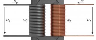
The windings are coils with wound insulated wire with a special varnish coating. The diameter of the wire and the number of turns depend on U and current (I), and this also affects P of the transformer. The number of coils must be at least 2, however, one coil is allowed provided that 2 windings are wound on it (one of which is primary).
Principle of operation
The principle of operation of T is quite simple and is based on finding a conductor with the number of turns n in an alternating magnetic field. An alternating magnetic field (AMF) is a field whose value and direction of magnetic flux (F) lines changes according to the law of changes in the values of the variable I that generates it over time. When current passes through the turns of the primary winding coil (KPO), an F is formed, which also penetrates the secondary winding coil (KVO).
Classification
Converters, in addition to the areas of operation described above, are usually classified according to their main characteristics, knowledge of which is necessary for their correct selection in various power electrical installations.
Series transformers are usually classified according to:
By type of installation
The class of current measuring devices is divided into several options for general or special purposes:
- Portable – special-purpose transformers used for control measurements or tests in mobile electrical laboratories;
- Overhead – special-purpose conversion devices used in high-voltage installations by placing the bushing insulators of the network power transformer circuits on top;
- Built-in – special type instrument transformers used inside various electrical devices and machines to convert values of the internal circuit of the equipment;
- Indoor installation – general-purpose electrical devices used on high-voltage electrical distribution systems, or low-voltage power circuits (400V);
- Outdoor installation – general-purpose conversion devices used in open high-voltage distribution networks (over 1000V).
Precise determination of the equipment in the circuit section to which serial converters will be connected becomes one of the important criteria for their selection.
By installation method
The type differences in the housings of series transformers of the electrical network divide them by installation class into:
- Feedthroughs - play the role of a feedthrough insulator through a certain obstacle in the electrical installation system. The leads of their primary windings are always located at the top, the other at the bottom;
- Support - structurally have all primary terminals located on one side. They are always installed on a flat supporting surface.
Correctly determining the type of installation of a measuring device for current conversion will prevent errors in the further design of a new energy system or repair of an already created installation.
By type of insulation
Groups of conversion measuring instruments have differences in the composition of the insulation material of their windings and housings, and are divided into several main ones:
- Solid - type of dry insulation in the form of porcelain, bakelite and similar materials;
- Viscous - insulation obtained by pouring with various compounds.
- Mixed - the use of paper-oil elements as an insulating material;
- Gas - the primary winding is isolated from the secondary winding by an air gap.
The insulating material of the equipment is selected depending on the type of electrical installation where it is used. It also depends on the rated voltage at the installation site of the devices, the climatic conditions where the switchgear will be operated and other factors.
By the number of transformation steps
Transformers are divided into two main types in this classification section:
- Single-stage - such devices have one primary and one secondary winding in the device, one unchangeable transformation ratio;
- Multistage - electromagnetic devices of a cascade type, the device of which contains either the ability to change the number of turns of the primary or secondary winding, or contains several secondary windings with a trim of their number of turns. This design allows you to have multiple transformation ratios in one device;
The first class of transformers is the most common in the use of general-purpose power plants. The second type is used in specialized areas of distribution networks as needed.
By the number of secondary windings
Accordingly, based on the number of transformation stages, devices are divided into:
- With one secondary winding;
- With two or more secondary windings.
The main type of transformers in this division classifies the first type as a general-purpose device, and the second as a special-purpose type.
By purpose
The main purpose of this electromagnetic device is to transform current from one value to another. There are two main directions for using transformers:
- For measurements – transfer of measuring parameters to instruments, the readings of which are taken by electrical installation personnel in order to analyze the operation of high-voltage power plants (>1000V). The primary winding of the current transformer is connected to a break in the energy circuit, and the required measuring device, such as an ammeter, wattmeter windings or electricity meters, is connected to its secondary winding. Their installation is carried out in power installations where direct connection of measuring equipment and electric meter windings directly is impossible, but their normal functioning is necessary.
- For protection – transfer of measurement information to protection devices, or any control modules of the energy system in which they are included. Ensures isolated operation of these devices in high-voltage installations or power circuits with a voltage of 400V. Isolation of relays and control devices from the primary circuit of the installation ensures safe accessibility to such modules by maintenance personnel for their repair and operation.
Often current transformers have mixed functionality.
By voltage class
An important criterion for choosing conversion devices. It includes two main classes:
- For high-voltage distribution installations - 6/10/35 kilovolts and above - the use of converters in such networks has an increased size and some design differences;
- For low-voltage switchgear - applications up to 1000V - the most common voltage class for such devices is 400V. In this class, the dimensions of transformers depend on the rated currents of the primary windings, and the design has significant diversity depending on the type of installation and the location of their installation site.
Incorrect selection of voltage class when choosing transformers will make their use impossible in a designed or operating energy system or section of it.
By conversion method
Due to the development of progress in electrical engineering, this parameter is now included in the main classification of conversion devices, consisting of types:
- Electromagnetic - conversion devices based on copper wire windings with a solid steel core, the most common cost-effective type of transformers, widely used in various distribution networks;
- Optical-electronic is a new type of current value conversion, based on the progressively innovative design of electromagnetic devices, their insulation, using the latest materials. Higher in price, but with more accurate output parameters.
Summarizing the above classification of electromagnetic equipment, the conclusion on their correct choice on the surface is only a complete study of all the listed parameters of current conversion devices, comparing them with the parameters of the power system where they will be operated, will not allow making unforgivable mistakes in their selection, further installation and quality use .
Current transformer selection
When deciding how to choose a current transformer, first of all, you must be guided by the requirements for installing the device.
Classification of current transformers
Transformers are divided into classes according to the type of installation, depending on the location of the device:
- Installation of CT in outdoor switchgear.
- TT installations in closed switchgear.
- For operation inside device enclosures and inside oil or gas environments, for example, inside high-voltage oil or SF6 circuit breakers.
- Special installation.
According to the installation method, depending on the design features of the device:
- Supporting, for installation on a flat supporting surface;
- Bushing CTs are located on busbars in complex switchgears and are used as a bushing insulator;
- Busbar - the peculiarity of this transformer is that the primary winding is played by the switchgear bus, which is passed through the window of the transformer; the device is mounted on the bus with special screws on a strip;
- Built-in ones are used for installation in power transformers, tank switches or conductors;
- Detachable, designed for quick installation on busbars or cables without disconnecting the current circuit.
By type of insulation:
- Cast insulation;
- Execution in a plastic case;
- The use of solid insulation using porcelain, bakelite, polymers, epoxy resin;
- Viscous insulation made from cast-in-place enveloping compounds;
- Oil-filled;
- Gas-filled, used for transformers installed at high and ultra-high voltages.
- Mixed insulation (paper-oil), the service life of paper insulation even after 40 years without use can remain very long.
Insufficient protection of the transformer can lead to moisture condensation on its bottom, the humidity can reach dangerous levels leading to electrical or thermal breakdown.
Depending on the number of transformation steps:
- Single-stage (one transformation ratio)
- Multi-stage or cascade (several transformation ratios)
By the number of secondary windings:
- The presence of one secondary winding.
- The existence of several secondary windings.
According to the functional purpose of the secondary winding:
- To measure or account.
- To perform protective functions.
- For measurement and protection.
- To perform measurements in various transient conditions.
By the number of transformation ratios:
- The presence of one transformation ratio.
- Several transformation ratios obtained after changing the number of turns in the windings or in the presence of several secondary windings.
Current transformers differ according to voltage class:
- Up to 1000 V.
- Above 1000 V.
Conversion methods:
- Electromagnetic.
- Optical-electronic.
By type of winding insulation:
- Solid insulation.
- Gas insulation
Table No. 1. Types of current transformers
Table No. 1. Types of current transformers
Table No. 1. Types of current transformers
Current transformer accuracy class
When choosing the right current transformer, you must, first of all, be guided by the scope of measurement where the current transformer will be used. If the CT, for example, will be used for AIMS KUE to take commercial metering readings, then it must have a high accuracy class.
CT errors primarily depend on the dimensions and design features of the magnetic circuit, as well as on the number of turns and cross-section of the winding wire. The error in readings is greatly influenced by the material from which the magnetic circuit is made.
When used in modern commercial accounting systems, CTs with a magnetic core made of nanocrystalline (amorphous) alloys are used; the CT acquires a high measurement accuracy class of 0.5, 0.5S. 0.2S, at low primary current.
Amorphous alloys, when increasing the CT accuracy class, help to increase the maximum power of the windings, improve the protection of measuring instruments connected in a circuit with a transformer, and reduce the aging effect to zero, which allows maintaining the characteristics of the device. This is how accurate and high-quality products are obtained that guarantee the stable functioning of AIMS KUE systems.
The high accuracy class creates the narrowest range of transformer errors.
The difference between accuracy classes is 0.5. 0.2 and 0.5S, 0.2S is the winding error class 0.5 or 0.2 below 5% of the rated current. This current value reveals an underestimation of electricity, which is reduced when using transformers with accuracy class S.
For various types of technical measurements, it is possible to connect transformers with accuracy class - 1. For use in connecting indicating ammeters, the use of CTs with accuracy class - 3 is permitted.
How to choose the right current transformer
The choice of current transformers is made based on certain values, these are: network voltage, rated primary current values, power depending on the load indicators of the consumer, transformation ratio.
Selection of current transformers by voltage
The rated voltage value (Unom) of the CT is selected greater than or equal to the value of the maximum operating voltage Uset.
Selecting a transformer based on primary current
The value (I1nom) of the rated current of the primary winding must be higher than or equal in value (Irabmax) to the operating rated installation current of the high-voltage line leaving the switchgear. Calculation of the choice of current transformer also depends on Ikz, the magnitude of the thermal impulse Ikz for 1 second, and the thermal impulse of the short-circuit current for 0.525 seconds, based on the results of protection operation.
When choosing the rated current of a transformer, they are guided by the need to meet the requirements for thermal and dynamic resistance to Is.
Selecting a current transformer by load
At low rated currents and high rated short-time thermal currents, the transformer is limited in power due to its size and maximum magnetomotive force. When the magnetizing force is doubled, the power increases fourfold. The power is limited by the dependence of the MMF on the dynamic current. The reason lies in the force of the electric field, which in the event of a short circuit will symmetry the turns of the primary winding against each other. Power is limited by the small overall dimensions of the CT.
Calculation of the choice of current transformer based on power is made depending on the cross-section of the current-carrying conductor and the calculated power.
Calculation formula depending on the cross-section of the conductor
Where Spr.selected is the selected conductor cross-section, (mm 2)
Load power calculation is determined by the formula
According to GOST, the CT load parameters are determined for current transformers with a rated power of 5VA and 10 VA with a lower limit set at 3.75 VA.
Current transformer selection table
Selecting a current transformer by transformation ratio
Installation of a current transformer with an overestimated transformation ratio is not allowed.
In the case of an increased coefficient, it is allowed to install meters at the consumer's receiving input. On power transformers, meters can be mounted on the low voltage side.
The greatest demand is for transformers that have one transformation ratio; it does not change throughout its entire service life.
An example of transformation ratios are CT 150/5 (N-30); 600/5 (N-120); 1000/5(N-200); 100/1(N-100)
Source
How to choose
The choice of current transformers (CTs) depends not only on knowledge of their classification in a general format, but also requires a correct assessment of many other transformer quantities. In electrical engineering, such values are usually called nominal parameters.
Ratings
The correct choice of CT consists of selecting your own nominal values, conducting test checks, the results of which will become fundamental for determining the required brand of transformers.
The main nominal parameters of the CT consist of:
Operating voltage
The value of the operating voltage - that is, the value of the effective voltage of the distribution installation where a certain instrument transformer is selected must be less than or equal to the rated voltage of the transformer. For effective selection, there is a standard range of operating voltage ratings, expressed in kilovolts: 0.66, 3, 6, 10, 15, 20, 24, 27, 35, 110, 150, 220, 330, 750.
CT primary current
The second main parameter for choosing a measuring device occurs in almost the same way as selecting the operating voltage: tabulated current standards of CT currents are compared with the value of the operating current of the circuit section or the entire electrical installation where the converter device is planned to be installed.
However, here one more criterion must be taken into account: in a network with active loads and general-purpose consumers, the ratings are selected without taking into account correction current margins, but for electrical equipment of generators, engines or other active-reactive consumers, it is necessary to take into account a 10% margin when choosing the primary CT current its size. This is due to surges in current values at the time of startup of such equipment.
The standard values by which the current of the primary winding of the transformer is selected are enclosed in a certain table row, the units of measurement are amperes: 1, 5, 10, 15, 20, 30, 40, 50, 75, 80, 100, 150, 200, 300, 400 , 500, 600, 750, 800, 1000, 1200, 1500, 1600, 2000, 3000, 4000, 5000, 6000, 8000, 10000, 12000, 14000, 16000, 18000, 20000, 25000, 28000, 30000, 32000, 35000 , 40000.
If the choice of primary current, taking into account the 10% margin, is between the standard values of the series, the larger of their values is taken.
However, here it is necessary to obtain data from two more mandatory tests of transformers in order to be completely sure of its correct choice:
Thermal resistance test
Thermal resistance ensures that the selected CT can withstand thermal shock and remain in normal operating condition, without any damage, in an emergency short circuit (SC) condition when a certain amount of short circuit current passes through it over a certain period of time. There is a special formula for test values for the thermal resistance of converter devices up to and above 1000 V.
If the selected transformer does not meet the calculated thermal resistance values, you should pay attention to another transformer model in order to avoid problems with the power plant during its further operation.
For electrodynamic resistance
This experimental-calculation process tests the selected transformer for resistance to the dynamic impact of short-circuit current on it during emergency operation in the circuit. An electromagnetic device must withstand such an impact for a certain period of time and remain in working condition.
Otherwise, a change in the brand or model of the transformer is required. The electrodynamic resistance test is determined by a special formula, which involves constant values and emergency mode values.
Secondary load power test
The third mandatory parameter for selecting a CT. The test is carried out by comparative analysis of the rated power of the CT and the total power of the secondary load over the entire section of the circuit in which the selected current transformer is planned to be installed. The power rating must be greater than or equal to the value in the existing or planned installation.
It is important to know that the total load power of the circuit is the sum of the resistances of all switching, measuring, relay devices and control equipment of the section multiplied by the square of the current of this equipment.
If the selection is carried out in the switchgear being designed, the resistance values are taken from the passport data of the equipment installed there; if the object is already operating, the resistance values are obtained by measuring the resistance of ohmmeters or other known methods.
Transformation ratio
This parameter is the final rating that must be taken into account for the correct selection of current transformers for instrumentation, relay system and control modules in distribution circuits.
The selection criterion for this parameter is divided into two options:
- From the minimum value of the transformation ratio - in this case, its value is taken based on the nominal value of the line of the switchgear into which the converter device is selected;
- From the maximum value of the transformation ratio - the value of the minimum transformation ratio multiplied by the ratio of the operating current of the line to the maximum value of the secondary winding current of the transformer.
The second parameter is regulated by the regulatory documents “PUE” (Rules for Electrical Installations) and is used when selecting current transformers used to power electricity metering windings.
Purpose
Taking into account the scope of application of transformers for their intended purpose establishes a strict choice of its accuracy class.
To power the commercial metering windings, it is necessary to select transformers with an accuracy class of at least 0.5. Household electricity metering limits the choice of transformation devices with accuracy class equal to 1
If the selection of CTs is made for measuring systems, such as ammeters, wattmeters, transformers with an accuracy class of at least 3 are selected
To power relay equipment or control devices in a distribution installation, the choice of transformers is dictated by a special high-rated accuracy class, which is designated 10 (P).
Without taking into account the scope of application, it is impossible to guarantee the correct choice of transformer, because its parameter called accuracy class significantly affects the accuracy of the readings taken and will be discussed in more detail in this article below.
Other criteria
Design institutes or technical specialists who select current transformers can be guided by other parameters for selecting converting devices for a section of a power plant circuit, such as:
- Determining the type of automation of the installation of the metering unit, which may affect the determination of the required accuracy class of the selected transformer;
- Calculations of the metering length and cross-section of conductors running from the transformer transformer to the metering devices in order to calculate the amount of voltage loss, which should have minimum percentage values;
- If a new power plant is designed from scratch, the method of converting the current value is taken into account.
- If the distribution network is operational, the current date of verification of the device becomes an important parameter for choosing a device. Transformation equipment should not have expired verification dates from metrological services.
Any current transformer parameter is selected based on and in accordance with the data described in the regulatory documentation of the “Rules and Devices of Electrical Installations”.
Information
This site has been created for informational purposes only. The resource materials are for reference only.
When quoting site materials, an active hyperlink to l220.ru is required.
Electricity metering with a current consumption of more than 100A is carried out by transformer connection meters, which are connected to the measured load through measuring transformers. Let's consider the main characteristics of current transformers.
1. Current transformer rated voltage
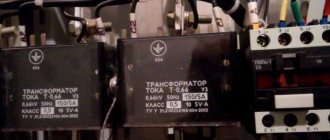
In our case, the measuring transformer should be 0.66 kV.
The accuracy class of measuring current transformers is determined by the purpose of the electric meter. For commercial accounting, the accuracy class must be 0.5S; for technical accounting, 1.0 is allowed.
3. Rated current of secondary winding
4. Rated current of the primary winding
This parameter is the most important for designers. Now we will consider the requirements for choosing the rated current of the primary winding of an instrument transformer. The rated current of the primary winding determines the transformation ratio.
The transformation ratio of an instrument transformer is the ratio of the rated current of the primary winding to the rated current of the secondary winding.
The transformation ratio should be selected according to the design load, taking into account operation in emergency mode. According to the PUE, the use of current transformers with an increased transformation ratio is allowed:
1.5.17. It is allowed to use current transformers with an increased transformation ratio (according to the conditions of electrodynamic and thermal resistance or busbar protection), if at the maximum load of the connection the current in the secondary winding of the current transformer is at least 40% of the rated current of the meter, and at a minimum operating load - at least 5 %.
In the literature you can also find requirements for the selection of current transformers. So, a current transformer should be considered overestimated in terms of transformation ratio if, at 25% of the calculated connected load (in normal mode), the current in the secondary winding will be less than 10% of the rated current of the meter.
Now let’s remember the mathematics and look at these requirements using an example.
Let the electrical installation consume a current of 140A (minimum load 14A). Let's choose a measuring current transformer for the meter.
Let's check the measuring transformer T-066 200/5. Its transformation coefficient is 40.
140/40=3.5A – secondary winding current at rated current.
5*40/100=2A – minimum current of the secondary winding at rated load.
As you can see 3.5A>2A – the requirement is met.
14/40=0.35A – secondary winding current at minimum current.
5*5/100=0.25A – minimum secondary winding current at minimum load.
As you can see 0.35A>0.25A – the requirement is met.
140*25/100 – 35A current at 25% load.
35/40=0.875 – current in the secondary load at 25% load.
5*10/100=0.5A – minimum secondary winding current at 25% load.
As you can see, 0.875A>0.5A – the requirement is met.
Conclusion: the T-066 200/5 measuring transformer for a 140A load is selected correctly.
For current transformers, there is also GOST 7746-2001 (Current Transformers. General Technical Conditions), where you can find the classification, main parameters and technical requirements.
When choosing current transformers, you can be guided by the data in the table:
Connection schemes
To power relay equipment, current windings for electricity metering for general or commercial purposes, there are three main circuits for connecting current transformers:
- "full star"
- "incomplete star";
- "triangle".
Each type of connection for various purposes optimizes the operation of measuring and metering systems of electrical equipment, and makes it possible to optimize the parameters of electricity metering in the circuits of new or existing distribution devices up to and above 1000 volts.
How to choose the right CT for relay protection
In order to correctly select current transformers for various relay protection and automation units, you should pay attention to several important parameters for their selection:
- The maximum and nominal voltage value in the primary winding of the transformer;
- Rated value of current in the primary winding;
- Accuracy class.
The last parameter has different values for different types of transformers, but for relay protection and automation units it has priority due to the fact that the accuracy of the output signal depends on it, in other words, the quality of power supply of the entire protection and automation unit. For more accurate operation of protection and automation systems in distribution networks, the use of transformers with an increased accuracy class of 10 (P) is used. A detailed discussion of the concept of accuracy class in the article is published below.
Selection of accuracy class
Current transformer parameter indicating that the measurement error of the current value of the secondary winding of the CT does not exceed the values specified in regulatory documents in accordance with GOST 7746-2011. According to this GOST, the nominal values of accuracy classes are as follows: 0.1, 0.2S, 0.2, 0.5, 0.5S, 1, 3, 5, 10.
For circuits of measuring instruments, metering equipment and relay protection systems, the accuracy classes of current converters will be different.
And for electricity metering of a general or commercial type, the usual accuracy classes of current converters are used equal to 1, 3. It should be added that to power measuring instruments such as ammeters and the like, current transformers with an accuracy class of 0.5 or increased accuracy are selected, the error of which is 0. 5S.
Automation and relay protection units require the use of high-precision equipment for their power sources in distribution networks, in which the error in the current value of the secondary winding of the transformer will not exceed 10% of the value. The marking of this accuracy class is 10 (P).
Power calculation
To select T as a power source, the permissible power of a consumer or group of consumers should be calculated. There are 2 options for collecting T: choosing from a table and making a calculation. Finding out the power of a transformer is quite simple; you need to use the power determination formula: P = U * I. The most accurate option is to calculate T as a power source.
There is a T available, the total power of which is 180 VA. It is necessary to determine the possibility of its use as a 160 VA power source. This method allows you to select a transformer by power according to the table.
Load factor Т: kз = Sp/Str. Sp - total design power: Sp = P/cosф = 180/0.8 = 225 VA. The cosph coefficient is assumed to be 0.8. Power power T Str = 160 VA. Based on this, kз = 225/160 = 1.4 (>1). If we take a T with a power of 250 VA, then kz = 225/250 = 0.9 ( S: 2000 > 1887.27 (fulfilled, therefore, the magnetic circuit is suitable for T).
Thus, the choice of a transformer by power to solve a specific problem can be made using a table or calculated and manufactured independently. The latter option allows a more flexible and high-quality approach to choosing T for any consumer. However, the approach of choosing a ready-made T significantly saves time.
Poroshin Andrey
Source
Calculation examples
As an example of the selection of current transformers, let us consider a calculation check of the correct choice of CT for an electricity meter in a distribution installation, with a rated current of 150A, with a minimum load of 15A.
T-0.66 200/5 is tested, with a transformation ratio of 40.
Secondary winding current at rated current: 150/40 = 3.75A;
Minimum secondary winding current at rated load: (5*40)/100 = 2A;
The resulting current of the secondary winding of the transformer being tested is greater than the obtained minimum current value, which indicates that the first test requirement has been met;
Let's calculate the minimum current of the secondary winding at minimum load: 15/40 = 0.38A;
Let's find out the minimum current in the secondary winding at minimum load: 5*5/100 = 0.25A;
0.38A> 0.25A – one more point does not go beyond the required rules for compliance of the selected current transformer;
Let's calculate the current value at ¼ load: 150*25/100 = 37.5A;
Let's calculate the value of the secondary winding current at ¼ load: 37.5/40 = 0.94A;
Let's find out the minimum current of the secondary winding at ¼ load: 5*10/100 = 0.5A;
Comparing both values of the secondary winding currents, we see that here the calculated value is normal: 0.94A> 0.5A;
Conclusion: the current transformer T-0.66 200/5 for electricity metering was selected correctly and complies with all standard “PUE” values.
Main characteristics of step-down transformers
When selecting a power step-down transformer, it is necessary to take into account the requirements for its design: the presence of a thermal fuse, the need for additional insulating impregnation, the method of fastening the transformer, as well as the length, type (rigid or flexible), location and color of the leads.
Below are the main characteristics of step-down transformers that you need to pay attention to when choosing and purchasing a step-down transformer:
- input voltage and current on the primary winding;
- maximum output power, also called the overall power of the transformer;
- output voltage and current on the secondary winding;
- transformer operating frequency;
- output voltage at rated load;
- current strength at rated load;
- rated output power;
- no-load current (this characteristic determines losses in the transformer);
- transformer phase;
- transformation ratio;
- maximum permissible voltage between the output terminals and ground;
- insulation resistance;
- primary and secondary resistance;
- pin type and configuration;
- mounting method (on a board, on a DIN rail, mounted);
- degree of protection of the transformer from the external environment (open and sealed transformers);
- Operating temperature range;
- overall dimensions and weight;
- transformer price.
Source
Tips and tricks for choosing
The main recommendation for the selection of current transformers is to carefully and fully use all parameters and criteria for selecting current transformers according to classification and equipment ratings equally, without taking any of them lightly.
The selection of current transformers, depending on their purpose, must necessarily comply with all regulatory documents and GOST standards in force at the current time of their selection.
When using automated programs for calculating the ratings of series transformers, double-checking the obtained values with several similar services will not be superfluous to confirm the correctness of the received data.
Types and their features
Devices used for voltage conversion are represented by various modifications. Depending on the type of core they are divided into:
- Rod;
- Armored;
- Toroidal.
The technical characteristics of step-down transformers are almost the same, while the manufacturing method for each of the presented types is special.
Let's watch the video, types and their classification:
Among the variety of models, the most widely used are dry step-down voltage transformers. But very often power devices that run on oil are also used.
They can be:
- One;
- Three-phase.
An electronic step-down transformer of the first type receives power from a network in which current flows through four wires, three of which are phase and one is zero. Single-phase ones receive current flowing through two wires. In residential buildings, these are the networks that are usually used.
Three-phase step-down power oil transformers have an ideal unity coefficient, and some of them can convert voltages equal to 600V. Typically, these parameters characterize large-sized devices used in production. Among the transformers there are electronic step-down transformers and compact ones designed for home use.
Equipment is also differentiated by output voltage. It can be either 12 or 380V. Perhaps some people assemble the transformer with their own hands. There are no particular difficulties in this, and instructions and diagrams can be easily found on the Internet.