In information-measuring circuits, reducing means play the first role. The circuit includes transmitting and receiving devices with measuring devices, electricity meters and specialized software. However, if the conversion error is high, the accuracy of the measuring instruments is meaningless. Therefore, with the development of high-precision equipment, the accuracy classes of current transformers are becoming particularly important.
They are an important characteristic that shows the compliance of the measurement error with the nominal values. It is influenced by many parameters.
General operating principle
A current passes through a power coil with a certain number of turns, overcoming the resistance in it. A magnetic flux is formed around it, which changes over time. Its vibrations are transmitted to a perpendicular magnetic circuit. This arrangement allows to reduce losses in the process of energy transformations.
Due to the oscillation of the magnetic field in the secondary windings, an electromotive force is generated. Overcoming resistance, a reduced current flows through the circuit of measuring instruments. The voltage is proportional to the input load and depends on the number of turns in the primary coil. In electromechanics, this ratio is called the transformation ratio.
The accuracy class represents the deviation of the real value from the nominal value.
What are they used for?
Various types of instrument transformers are found both in small matchbox-sized devices and in large power installations. Their main purpose is to reduce primary currents and voltages to the values required for measuring devices, protective relays and automation. The use of step-down coils provides protection for the lower and higher rank circuits, since they are separated from each other.
Reducing agents are divided according to characteristics of operation and are intended for:
- measurements. They transmit secondary current to devices;
- protection of current circuits;
- applications in laboratories. Such reducing agents have a high accuracy rating;
- repeated conversion, they belong to intermediate instruments.
Reducing devices are divided by type of installation: external, internal, portable and overhead, as well as by the type of insulation materials and transformation ratio.
Measurement
An instrument transformer is necessary to reduce the high current of the main voltage and transfer it to measuring devices. Connecting standard devices to a high-voltage network would require cumbersome installations. It is neither economically profitable nor advisable to sell instruments of this size.
The use of step-down transformers allows the use of conventional measuring devices in normal mode, which expands the range of their applications. Due to the reduced voltage, they do not require additional modifications. The transformer separates the high-voltage network voltage from the supply voltage of the devices, ensuring safety from use. The accuracy of electrical energy metering depends on their class.
Protection
In addition to powering measuring instruments, step-down transformers supply voltage to protection and automatic blocking systems. Because voltage drops and surges occur in the network electrical network, which is detrimental to high-precision circuit equipment.
In power plants, equipment is divided into power and secondary, which controls the processes of the primary device connection circuit. High-voltage equipment is located in open areas or devices. Secondary equipment is located on relay strips inside distribution cabinets.
The intermediate element for transmitting information between power units and measuring, control, monitoring and protection devices are step-down or instrument transformers. They separate the primary and secondary circuits from the harmful effects of power units on sensitive measuring instruments, and also protect operating personnel from damage.
Accurate metering: current transformers
The energy saving policy being implemented in the Russian Federation, as well as the growing cost of electrical energy, require more and more efficient accounting. For this purpose, automated electricity metering systems are being created, and enterprises employ specialists to service them. To create and operate such systems, not only additional capital investments are required, but also solutions to a number of technical problems, one of which will be discussed in this article.
The lowest level in the hierarchy of automated accounting systems is the level of the information and measurement complex (IMC). It includes instrument transformers, electrical energy meters, and secondary circuits of instrument transformers. It is very important at the stage of building an IMC to minimize its error, which largely depends on the correct choice of current and voltage measuring transformers (CTs). The problems of choosing a heating element are a separate topic that is not covered by this material. It is only worth noting that, unlike CTs, their errors do not depend on the changing load in the controlled circuit. With TT everything is much more complicated.
Often designers and operating organizations do not take the choice of CTs for accounting seriously enough. A CT with the best accuracy class is selected, without focusing on its other parameters. They do this being confident that using CTs with the best accuracy class is already saving money. The reason for this is either the inability to choose the right CT, or the desire to save money: available current transformers are installed, or CTs are selected that are less expensive and easier to install, despite the limitations of their metrological characteristics. The result is significant financial losses resulting from the lack of accurate accounting.
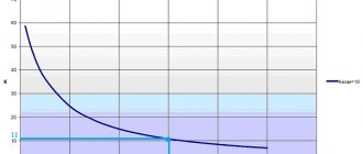
The requirements for current transformers used in our country are regulated by GOST 7746-2001 (1). Among other characteristics, this standard specifies a number of primary currents and secondary current values (1 and 5 A) with which CTs can be manufactured. Also regulated are the primary current measurement ranges at which the accuracy class must be maintained: from 5-120% for accuracy classes 0.5 and 0.2, from 1-120% for classes 0.5S and 0.2S. Thus, accuracy classes with the letter “S” differ from others by an increased measurement range in the area of minimum values (from 5% to 1%). In addition, there is a requirement of the PUE (clause 1.5.17) (2), according to which it is necessary to select the transformation ratio so that the current in the maximum load mode of the connection is at least 40% of the meter current, and in the minimum mode - at least 5%. And the meter current, as a rule, is equal to the secondary current of the CT, so the above requirement can be safely attributed to the metering winding of the measuring transformer. It is worth noting that the minimum operating requirement is contrary to GOST 7746, because makes the use of TT accuracy classes with the letter “S” inappropriate. As for the requirement of 40% in maximum mode, it is probably based on the desire to minimize CT errors of classes without “S” (see Fig. 1), while for classes 0.2S and 0.5S it would be more appropriate to apply the criterion “20%”, due to the increase in errors when the primary current decreases below this value (see Fig. 2).
Rice. 1. Current and angular errors of CT accuracy classes 0.2; 0.5; 1
Rice. 2. Current and angular errors of CT accuracy classes 0.2S; 0.5S
So, when choosing a CT transformation ratio, it is necessary to “kill two birds with one stone”: not only to “fit” into the range specified by GOST 7746-2001, but also to comply with the requirement of the PUE.
How to calculate the error
The error of instrument transformers is determined by their design feature. The accuracy is affected by the geometric dimensions and shapes of the magnetic cores, the number of turns and the diameter of the winding wire. The material from which the magnetic core is made also has a great influence.
Such characteristics of electromagnetic materials at low currents of the first winding have an error of 1-5%, so their accuracy is very low. Designers strive to achieve class at this scale. Amorphous materials are used instead of structural steels.
To calculate the accuracy class, use the following formulas:
- error in current value: (delta)I = I2 – I1, where I2 is the current in the secondary winding, I2 is the power circuit current;
- error in shift angle: (alpha) = (alpha)2 – (alpha)1, where (alpha)2 = 180 degrees, (alpha)1 – actual shift angle.
Errors in angle and current magnitude explain the effect of magnetizing voltage.
What requirements must be met for commercial electricity metering?
Modern technologies make it possible to produce transformers from 6 to 10 kV with the number of coils up to four pieces. Each reel has its own accuracy class. It is selected based on the area of application. Each provides its own set of testing.
For commercial metering devices, coils with ratings of 0.2S and 0.5S are used. They have high magnetic field permeability. The letter "S" indicates testing of the transformer at five points in the range from 1-120% of the rated voltage.
The check scheme looks like 1x5x20x100x120. For classes 1; 0.5 and 0.2 testing is performed at four points 5x20x100x120%. For relay and automatic protection, three points 50x100x120 are used. Such transformers are classed with the letter “Z”. Requirements for the accuracy class are presented in GOST 7746-2001.
Accuracy class is the most important characteristic of a current transformer
The accuracy class of a current transformer is one of the most important characteristics of a CT, which indicates that its measurement error does not exceed the values established in regulatory documents. The error, in turn, depends on many factors.
Currently, it is possible to manufacture current transformers for 6-10 kV with a number of windings up to four, and each winding can be made with its own accuracy class. For example, 0.5/10Р, 0.5S/10Р, 0.2S/0.5/10Р, 0.2S/0.5/5Р/10Р.
The accuracy class for each winding is selected based on its purpose. Each accuracy class has its own test program.
For commercial metering, as a rule, windings with accuracy classes of 0.5S and 0.2S are used. The letter “S” indicates that the current transformer is tested at five points from 1% to 120% (1-5-20-100-120) of the rated current. Windings of accuracy classes 1, 0.5, 0.2 are checked only at four points: 5-20-100-120% of the rated current. For relay protection, windings with accuracy classes 10P or 5P are used and these windings are checked at three points: 50-100-120% of the rated current of the transformer. Such windings correspond to accuracy class “3”.
More detailed requirements for accuracy classes of current transformers are presented in GOST 7746-2001.
Below is a table of permissible errors for various accuracy classes:
Permissible errors for various CT accuracy classes
Requirements for accuracy classes of current transformers represent a certain range within which the transformer errors must fit. The higher the accuracy class, the narrower the range.
The difference between accuracy classes 0.5S and 0.5 (0.2S and 0.2) is that the winding error of class 0.5 is not standardized below 5% of the rated current. Apparently, this is why the PUE requires that the minimum current in the secondary winding of the transformer be at least 5%. In my opinion, this requirement has long been outdated, because The error of current transformers with an accuracy class of 0.5S is normalized starting from 1%.
Difference between accuracy classes 0.5S and 0.5
The use of current transformers of accuracy classes 0.5S and 0.2S makes it possible to reduce under-metering of electricity several times with low load on power transformers.
It turns out that it is possible to manufacture current transformers with different transformation ratios of measuring and relay windings. For example, the measuring winding is 200/5 (cf. tr. 40), relay winding 400/5 (cf. tr. 80). But it is worth keeping in mind that checking the current transformer for resistance to short-circuit currents. should be carried out along the winding with a minimum transformation ratio.
I recommend reading:
Are you working in the Dialux program?
How to use regulatory documents?
Assessment of the degree of physical wear of electrical equipment
The effect of electric current on the human body
Table of permissible errors for commercial accounting
For commercial metering devices there is an error table.
| Class | Primary voltage as a percentage of rated value | Current error limit in percent | Angle error limit |
| 0,2 | 5 | 0,75 | 30 |
| 20 | 0,35 | 15 | |
| 100-120 | 0,2 | 10 | |
| 0,5 | 5 | 1,5 | 90 |
| 20 | 0,75 | 45 | |
| 100-120 | 0,5 | 30 |
The requirements for the accuracy class of converters are the ranges within which the errors must fall. As accuracy increases, the spread of values decreases.
The difference between converters with and without the “S” marking, for example, 0.5 and 0.5S, is that the former are not rated below 5% of the rated current.
What is the difference between accuracy classes 0.5 and 0.5 s
The current transformer is an important link in a complex chain of information and measurement systems. At the same time, the accuracy of the readings of such equipment is of particular relevance, because with a low value, such equipment will lose its suitability. All requirements for the main accuracy classes for these measuring instruments are specified in the current standard. The term accuracy class itself is not a metrological term; it was invented by instrument creators and later adopted by metrologists.
There are different measurement accuracy classes for these transformers, based on which you can select the most accurate device.
Each such device gives a certain amount of error; not all kW spent are taken into account, as a result of which energy sales companies incur certain losses every year. The error in taking into account a small eye always has a negative value; this is important to know when making the necessary calculations. The most common accuracy classes today are 0.5 S. What is the difference in these 2 fairly similar quantities? This needs to be sorted out.
Benefits of using high precision transformers
Instrument transformers with a high accuracy class have a number of advantages:
- resistance of measuring parameters to magnetization by direct voltage;
- high coefficient of electrical resistance of the materials used;
- reduction of losses due to eddy currents and magnetization reversal of the rod;
- high accuracy class margin;
- long service life;
- reduction in dimensions and materials for manufacturing, which affects the overall weight of the installation;
- high resistance to electrical energy theft.