No matter how electronics develops, it is still not possible to abandon such a device as a transformer. Each reliable power supply and voltage converter contains this electromagnetic device with galvanic isolation of the windings. They are widely used both in production and in everyday life, and are a static electromagnetic device that works on the principle of mutual induction. Such devices consist of two main elements:
- closed magnetic circuit;
- two or more windings.
The windings of transformers do not have any connection with each other, except inductive. It is designed to convert only alternating voltage, the frequency of which, after transmission through the magnetic circuit, will be unchanged.
Calculation of the transformer parameters is necessary so that one voltage is supplied to the input of this device, and a reduced or increased voltage of a different specified value is generated at the output. In this case, it is necessary to take into account the currents flowing in all windings, as well as the power of the device, which depends on the connected load and the purpose.
Any even simple calculation of a transformer consists of an electrical and structural component. Electrical part includes:
- Determination of voltages and currents flowing through the windings;
- Determination of transformation ratio.
Structural ones include:
- Core dimensions and device type;
- Choice of transformer core material;
- Possible options for closing housing and ventilation.
Magnetic induction flows through one square centimeter of the cross-section of the magnetic circuit; its unit of measurement is Tesla. Tesla, in turn, is an outstanding physicist, after whom she is named. This value directly depends on the frequency of the current. And so at a frequency of 50 Hz and, say, 400 Hz, the induction (Tesla) values will be different, which means the dimensions of the device decrease with increasing frequency.
After this, the voltage drop and losses in the magnetic circuit are determined; at the stage of electrical calculation, all these values are determined only approximately. Calculation of the load in the transformer is key in its execution. In welding, for example, the load feature is expressed from the short circuit mode. The large value of the short circuit current is associated with the low value of the transformer resistance under these operating conditions.
The most important element of all formulas for this calculation is the transformation ratio, which is defined as the ratio of the number of wound turns in the primary winding to the number of turns in the secondary winding. If there are not two windings, but more, then, accordingly, there will also be several such coefficients. If the winding voltages are known, then it can be calculated as the ratio of the voltages of the primary winding to the secondary.
Calculation of a single-phase transformer
Features of the application and design of welding transformers
When calculating step-down single-phase current transformers, as the most common in everyday life, you first need to find out its power. Of course, you can lower the voltage in other ways, but this is the most effective and also provides galvanic isolation, which means the ability to connect a power load.
For example, if the voltage of the primary winding is 220 Volts, which is typical for standard single-phase current networks, then the secondary voltage must be determined by the load that will be connected to it. This can be either lower or higher voltage. For example, to charge car batteries, a voltage of 12-14 Volts is required. That is, the secondary voltage and current must also be known in advance.
Approximate power will be equal to the product of current and voltage. It is also worth considering efficiency. For power devices it is approximately 0.8–0.85. Then, taking into account this efficiency, the calculated power will be:
Calc = P*efficiency
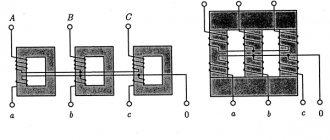
It is this power that forms the basis for calculating the cross-section of the core on which the windings will be wound. By the way, there can be several types of these magnetic cores, as shown in the figure below.
Next, using this formula we determine the cross section
S (cm2) = (1.0 ÷1.3) √Р
The coefficient 1–1.3 depends on the quality of electrical steel. Electrical steel includes pure iron in the form of sheets or strips 0.1–8 mm thick, or in the form of rolled products (round or square) of various sizes.
After which the number of turns per volt of voltage is determined.
N = (50 ÷70)/S (cm2)
We take the average value of the coefficient 60.
Now knowing the number of turns per volt, it is possible to calculate the number of turns in each winding. All that remains is to find the cross-section of the wire that will be used to wind the windings. Copper is the best material for this, as it has high conductivity and cools quickly when heated. Wire type: PEL or PEV. By the way, heating of even the most ideal electromagnetic device is inevitable, so when manufacturing a network transformer, the issue of ventilation is also relevant. To do this, at least provide a natural ventilated structure on the body by cutting holes.
The current in the winding is
I=P/U
The cross-sectional diameter of the conductor for the winding is determined by the formula:
D= (0.7÷0.9)√I
where 0.7-0.9 is the current density coefficient in the conductor. The higher its value, the less the wire will heat up during operation.
There are many methods for calculating characteristics and parameters, this one is the simplest, but also approximate (imprecise). A more accurate calculation of transformer windings is used for production and industrial needs.
How to calculate the number of turns of the primary winding?
Yes, until now we have proceeded from the assumption that the primary winding is intact. What to do if it turned out to be torn or burned to the ground?
A broken winding can be unwound, the break restored, and re-wound. But the burnt winding will have to be rewound with a new wire.
Of course, the easiest way is to count the number of turns when removing the primary winding.
If you don’t have a counter, and you, like me, use a device based on a hand drill, then you can calculate the amount of reduction of the drill and count the number of full turns of the drill handle. Until I came across a revolution counter at the market, I did just that.
But, if the winding is severely damaged or does not exist at all, then you can calculate the number of turns using the given formula. This formula is valid for a frequency of 50 Hertz.
ω = 44 / (T * S)
ω – number of turns per volt,
44 – constant coefficient,
T – induction value in Tesla,
S is the cross-section of the magnetic circuit in square centimeters.
Example.
The cross-section of my magnetic circuit is 6.25 cm².
The magnetic core is twisted and armored, so I choose 1.5 T induction.
44 / (1.5 * 6.25) = 4.693 volts/volt
We determine the number of turns of the primary winding taking into account the maximum network voltage:
4.693 * 220 * 1.05 = 1084 vit.
Permissible network voltage deviation accepted in most countries: -10… +5%. Hence the coefficient is 1.05.
The magnitude of induction can be determined from the table.
| Type of magnetic circuit | Magnetic induction max (T) at transformer power (W) | ||||
| 5-15 | 15-50 | 50-150 | 150-300 | 300-1000 | |
| Armor stamped | 1,1-1,3 | 1,3 | 1,3-1,35 | 1,35 | 1,35-1,2 |
| Armor twisted | 1,55 | 1,65 | 1,65 | 1,65 | 1,65 |
| Toroidal twisted | 1,7 | 1,7 | 1,7 | 1,65 | 1,6 |
You should not use the maximum induction value, as it can vary greatly for magnetic cores of different quality.
Return to top menu
Pages 1 2 3 4
July 5, 2010 (20:38) in Power supplies, DIY, Technology
Calculation of a three-phase transformer
Features of the application and selection of measuring current transformers
Manufacturing a three-phase transformer and its precise calculation is a more complex process, since here the primary and secondary windings already consist of three coils. This is a type of power transformer, the magnetic circuit of which is most often made using the rod method. Here such concepts as phase and linear voltages already appear. Linear ones are measured between two phases, and phase ones between a phase and ground. If a three-phase transformer is designed for 0.4 kV, then the linear voltage will be 380V, and the phase voltage 220V. The windings can be connected in a star or triangle, which gives different values of currents and voltages.
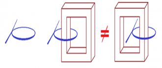
The windings of a three-phase transformer are located on the rods in the same way as in a single-phase one, i.e., the low voltage LV windings are placed closer to the rod, and the higher voltage HV windings are located on the lower voltage windings.
High-voltage three-phase current transformers are calculated and manufactured exclusively in industrial conditions. By the way, any step-down transformer, when switched back on, acts as a voltage-increasing device.
How to calculate transformer power
Most often, the need to calculate the power of a transformer arises when working with welding equipment, especially when the technical characteristics are unknown in advance.
The power of the transformer is closely related to the current and voltage at which the equipment will function normally. The simplest option for calculating power is to multiply the voltage value by the amount of current consumed by the device. However, in practice, not everything is so simple, primarily due to differences in the types of devices and the cores used in them. As an example, it is recommended to consider W-shaped cores, which are most widely used due to their availability and relatively low cost.
Calculation of a toroidal transformer
The task and features of grounding transformers.
This design of transformers is used in electronic equipment; they have smaller dimensions, weight, and increased efficiency. Due to the use of a ferrite rod, there is virtually no interference, which makes it possible not to shield these devices.
A simple calculation of a toroidal transformer consists of 5 points:
- Determination of the power of the secondary winding P=Un*In;
- Determination of the overall power of the transformer Pg=P/efficiency. Its efficiency is approximately 90-95%;
- Core cross-sectional area and dimensions
- Determining the number of turns per volt and, accordingly, the number of turns for the required voltage.
- Calculation of the current in each winding and selection of the conductor diameter is done in the same way as in single-phase power transformers described above.
Selection of current transformers for a 0.4 kV electric meter
Electricity metering with a current consumption of more than 100A is carried out by transformer connection meters, which are connected to the measured load through measuring transformers. Let's consider the main characteristics of current transformers.
1 Rated current transformer voltage.
In our case, the measuring transformer should be 0.66 kV.
2 Accuracy class.
The accuracy class of measuring current transformers is determined by the purpose of the electric meter. For commercial accounting, the accuracy class must be 0.5S; for technical accounting, 1.0 is allowed.
3 Rated current of the secondary winding.
Usually 5A.
4 Rated current of the primary winding.
This parameter is the most important for designers. Now we will consider the requirements for choosing the rated current of the primary winding of an instrument transformer. The rated current of the primary winding determines the transformation ratio.
The transformation ratio of an instrument transformer is the ratio of the rated current of the primary winding to the rated current of the secondary winding.
The transformation ratio should be selected according to the design load, taking into account operation in emergency mode. According to the PUE, the use of current transformers with an increased transformation ratio is allowed:
1.5.17. It is allowed to use current transformers with an increased transformation ratio (according to the conditions of electrodynamic and thermal resistance or busbar protection), if at the maximum load of the connection the current in the secondary winding of the current transformer is at least 40% of the rated current of the meter, and at a minimum operating load - at least 5 %.
In the literature you can also find requirements for the selection of current transformers. So, a current transformer should be considered overestimated in terms of transformation ratio if, at 25% of the calculated connected load (in normal mode), the current in the secondary winding will be less than 10% of the rated current of the meter.
Now let’s remember the mathematics and look at these requirements using an example.
Let the electrical installation consume a current of 140A (minimum load 14A). Let's choose a measuring current transformer for the meter.
Let's check the measuring transformer T-066 200/5. Its transformation coefficient is 40.
140/40=3.5A – secondary winding current at rated current.
5*40/100=2A – minimum current of the secondary winding at rated load.
As you can see 3.5A>2A – the requirement is met.
14/40=0.35A – secondary winding current at minimum current.
5*5/100=0.25A – minimum secondary winding current at minimum load.
As you can see 0.35A>0.25A – the requirement is met.
140*25/100 – 35A current at 25% load.
35/40=0.875 – current in the secondary load at 25% load.
5*10/100=0.5A – minimum secondary winding current at 25% load.
As you can see, 0.875A>0.5A – the requirement is met.
Conclusion: the T-066 200/5 measuring transformer for a 140A load is selected correctly.
For current transformers, there is also GOST 7746-2001 (Current Transformers. General Technical Conditions), where you can find the classification, main parameters and technical requirements.
When choosing current transformers, you can be guided by the data in the table:
Selection of current transformers by load
Please note that there are typos there
I recommend reading:
Fuse selection
Calculation of overhead lines (VLI) based on voltage loss
Program for calculating the loads of public buildings
When choosing an electric stove, they don’t think about this, and then they bite their elbows
Calculation of a transformer for a semi-automatic welding machine
The semi-automatic welding machine is designed for welding with mechanical supply of a special welding wire instead of an electrode. The power source of such a device is also based on a powerful transformer. The calculation is based on the principle of its operation, the output of which should be 60 Volts at idle. It operates in short-circuited mode, so heating of its windings is normal. The calculation is also similar in principle, only in this case it is also worth taking into account the power during prolonged welding
Pdl = U2I2 (PR/100)0.5 *0.001.
The voltage and strength of one turn is measured in volts and it will be equal to E=Pdl0.095+0.55. Knowing these values, you can proceed to a full calculation.
Calculation of a pulse transformer of a push-pull converter
The advantage of push-pull converters is their simplicity and the ability to increase power. In a properly designed push-pull converter, a constant current passes through the winding, so there is no strong core bias. This allows you to use a full magnetization reversal cycle and get maximum power. Since it is performed on a ferrite core, the calculation of the output voltage of the transformer is similar to a conventional toroidal one.
You can simplify the transformer calculation options by using special calculation calculators, which are offered by some online resources. One has only to enter the desired data, and the machine will provide the necessary parameters of the planned electromagnetic device.