Power source using hydraulics as an example
Let's look at a water tower that has automatic water supply. That is, no matter how much water we consume from the tower, its water level will remain unchanged.
Schematically it will look like this:
A tower with automatic water supply can be considered a power source. In chemical power supplies, a discharge occurs, which leads to the voltage level decreasing during prolonged operation. And what is voltage by analogy with hydraulics? This is the same water level)
Let's cut off the top part of the water tower for clarity. We will get a cylinder that is filled with water. Let's take the ground level as a reference point. Let it be equal to zero.
Now the final question. In which case will the pressure on the bottom be greater? When there is little water in the tower
or when the tower is completely flooded with water so that even the water overflows its edges
Of course, when the tower is only half filled with water , the pressure at the bottom of the tower is less than when the tower is full of water .
I think there is no need to explain that if there is no water in the tower at all, then there will be no pressure at the bottom of the tower.
A battery or accumulator works on the same principle.
On electrical diagrams, its designation looks something like this:
Also, to obtain the required voltage, single-cell power supplies are connected in series. In the diagram it looks like this:
Any battery or DC source has two poles: “plus” and “minus”. The minus is the ground level, as in our example with the water tower, and the plus is the voltage, by analogy with hydraulics this will be the same water level.
Combined operation of several power supplies for one load
Many beginners in electronics often have problems with insufficient power (current) of power supplies or insufficient voltage. To get around this problem, several sources are often connected in parallel or in series. What happens and how to do it correctly will be discussed below.
Parallel and series connection of elements has long been known and used in practical circuitry to obtain specified values of elements. Using an example of connecting resistors, it looks like this:
Picture 1
But a resistor or capacitor has only one main parameter - the value and connection option simply changes their resulting (total) value.
In practice, parallel (sometimes electrochemical) and series connections of power supplies are often used.
A series connection is used to increase the resulting voltage, and a parallel connection is used to increase the total current consumption.
Series connection of electrochemical power supplies
When connected in series, the parameters (E and Ri) are simply summed up,
Figure 2
Most importantly, you should know:
As I already said, each power source (of any type) has its own characteristics, which can be reduced to static characteristics that completely determine its characteristics - Ri, U(E); These characteristics of chemical current sources can vary from instance to instance or randomly over time (they depend on many parameters at each stage of the technological process of their production);
There are no two absolutely identical power sources, just like any electronic components. (although in order to somehow limit the scatter, grouping of components is used, according to a number of ratings and a range of accuracy).
Therefore, with a series connection, the operating time of chemical current sources is determined by the worst in the chain. As it loses capacitance, its internal resistance will increase and limit the current drawn by the load.
With a parallel connection, everything is much more complicated.
This is where most of the problems arise.
Parallel connection of electrochemical power supplies
When connecting electrochemical power elements (sources) in parallel, problems arise if measures are not taken.
The fact is that these elements have several parameters that determine their characteristics.
This:
Voltage (EMF) is E, and internal resistance is Ri.
It’s worth clarifying right away that these parameters are purely individual and therefore they are quite rarely repeated even in the same game.
Figure 3
Let's look at Figure 3, with a parallel connection of two different power sources (electrochemical element) having equal internal resistance (For example, 0.25 ohms, total 0.5) and different output voltages (U1 = 2.2 V, U2 = 2.1 V , ΔU=0.1 V) a flow current Iper equal to 0.2 A appears between them.
This current will exist even when the load is turned off, until the voltage at the sources is equal. When the best electrochemical element is discharged into a worse one, this is a loss of their total capacity.
Therefore, parallel connection of individual elements of electrochemical current sources is not recommended. It is possible to parallel connect (redundant) serial batteries of cells using special protection devices (see Fig. 6) against overflow currents or switches.
Photovoltaic cells - solar cell elements
A slightly different situation occurs when connecting solar cell elements in parallel, which is determined by the properties of the solar cell itself. This is the generation of current under the action of light quanta falling on a flat pn junction of a sufficiently large area. The solar cell has a current-voltage characteristic similar to a semiconductor diode with corresponding deviations inherent in large-area pn junctions.
Therefore, there are no flow currents for the solar cell. But the presence of ΔU in parallel-connected elements leads to the fact that with low current draw, the element with a lower voltage is simply turned off. And with high power take-off, the load current of each element is different and is determined by the load current on each element at a given load voltage U. see fig. 5.
Figure 4
Let's look at the example of the volt-ampere characteristic of a solar battery element, what happens when they are connected in parallel, as shown in Fig. 1b. An approximate graph of the current-voltage characteristic is given below.
Figure 5
In Fig. 5 we see that at equal voltage Un, element SC3 generates a current I1 less than the current generated by element SC4 equal to I2. As a result, the total load current is equal to:
Iload = (I1+I2)
That is, for a given Un, the power supplied by elements connected in parallel is equal to:
Series connection of power supplies
Now let's imagine this situation. What will happen if in our trimmed water tower full of water we add another one full of water on top? Schematically it will look something like this:
Do you think the pressure on the ground will decrease or increase? It is clear that it will increase! Yes, and exactly twice as much! Why did it happen? The water level has become higher, therefore, the pressure on the bottom has increased .
If the negative of one battery is connected to the positive of another battery, then their total voltage is summed up.
A fully charged battery will look like a tower completely filled with water, given that the automatic water supply pump is running. By analogy, a pump is an EMF.
A half-dead battery will look something like this:
We can say that the pump can no longer cope.
A battery set to “zero” will look like this:
The automatic water supply pump has broken down.
Naturally, if you connect a fully charged and half-dead battery in series, their total voltage will look something like this:
Let's demonstrate all this in practice. So we have 2 lithium-ion batteries. I marked them with numbers 1 and 2. I brought out a red wire from the plus of each battery, and a black wire from the minus.
Let's measure the voltage of battery No. 1 using a multimeter. I also wrote how to do this in the article How to measure current and voltage with a multimeter.
On the first battery we have a voltage of 3.66 Volts. This is a typical value for a lithium-ion battery.
In the same way we measure the voltage on battery No. 2
Oh, what a coincidence). The same 3.66 Volts.
In order to connect these batteries in series, we need to do something like this:
Just like in towers, we need to connect the base of one tower to the top of another tower. In power sources, such as batteries or batteries, we need to connect the minus of one battery to the plus of the other. That's what we'll do. We connect the plus of one battery with the minus of the other and we get... the sum of the voltages of each battery! As you remember, on the first battery we had a voltage of 3.66 V, on the second also 3.66 V. 3.66 + 3.6 = 7.32 V.
The multimeter shows 7.33 V. We will attribute 0.01 V to measurement error.
This property works not only with two batteries, but also with an infinite number of them. I don’t think it’s worth saying that if you put 100 of these batteries in a row, connect them in series and touch the outer poles with your bare hands, then all this can even end in death.
Parallel connection of power supplies
But what happens if the power supplies are connected in parallel? Let's look at this from the point of view of the same hydraulics. We have the same towers, in which there is water to the very edges:
No, we will not be perverted here. We will simply connect our towers at the very base with a pipe:
Will the pressure at the bottom of each tower change? I think no. It will remain the same as in one of the towers. What has changed? Just the volume of water . It has doubled in size.
But you can say that in the first case we also had 2 times more water!
Yes, this is all true, but what is important here is that the pressure on the bottom of the tower has changed and has also become twice as large. If we make an inset of the same diameter right at the foot of the water tower, then in the case where the water towers stand one on top of the other, the force of the water flow will be twice as fast as if we made exactly the same inset in the picture where we connected the water towers with a pipe. I voiced this idea in more detail in an article about Ohm’s Law.
If we project this whole idea onto our power supplies, it turns out that with a series connection we have the voltage summed up, and with a parallel connection the current strength must be summed up. But this does not mean that the load, which consumed, for example, 1 Ampere, after we connect it to two parallel power sources, will consume 2 Amperes. With a parallel connection, the voltage remains the same, but the battery capacity increases. But the load will still consume the same 1 Ampere, otherwise all this would contradict Ohm’s law.
It's time to look at all this using a real example. So, we have already taken measurements. It remains to connect two power sources in parallel, in our case these are li-ion batteries:
As you can see, the voltage has not changed.
When connecting power supplies in parallel, the condition must be met that they must have the same voltage.
Just think about what could happen if one of the towers is empty?
I think it is not difficult to guess that water from one tower will flow into another tower until their level is equalized (the law of communicating vessels), if the pump of one tower breaks down and it is empty.
It's the same with power supplies. Power supplies of different voltages must not be connected in parallel . This is fraught with the fact that you will kill healthy batteries, and dead ones will remain dead or charge a little. If the difference between the battery voltages is large, then a crazy amount of current can flow in such a circuit, which will cause heating and even fire of the batteries.
Do not connect power supplies of different voltages in parallel
In practice, several sources of electrical energy are connected into a group - a battery of electrical energy sources. The connection to the battery can be serial, parallel or mixed.
In a series connection, the positive pole of the previous source is connected to the negative pole of the next one.
The total EMF of the circuit is equal to the algebraic sum of the EMF of the individual elements, and the internal resistance of the battery is equal to the sum of the source resistances:
Fig.7
e=Si=1ei,
r=Si=1ri,
This can be explained by the fact that with a series connection, the electric charge alternately passes through a source of electrical energy and acquires energy in each of them. The internal resistance of the battery also increases.
When identical sources are connected in series with emf e and internal resistance r, the emf of the battery and its internal resistance are equal.
eb=e*n,
Rb=R*n
where n is the number of sources.
Ohm's law for a complete circuit with identical current sources connected in series is written as;
I=(e*n)/(R+r*n)
where e and r are the emf and internal resistance of one source, R is the resistance of the external section of the circuit, I is the current strength in the circuit.
Fig.8
For example, a complete circuit contains several current sources, the emf of which is equal to E1, E2, E3 and the internal resistance is r1, r2, r3, respectively. The emf acting in the circuit is equal to:
eb=e1 -e2+e3-e4
The battery resistance is:
r,, = r, + r, + r, + g.
At the same time, we take into account that positive emfs are those that increase the potential in the direction of bypassing the circuit, i.e. the direction of circuit bypass coincides with the transition inside the source from the negative pole of the source to the positive one.
Series connection of current sources is used in cases where it is necessary to increase the voltage on an external circuit, and the resistance of the external circuit is large compared to the internal resistance of one source.
Rice. 9
When connecting sources in parallel, all of them are positive
the poles are connected to one conductor, and the negative ones to the other.
The total EMF of the circuit (the entire battery is equal to the EMF of one source: eb = e, and the internal resistance of the battery is:
Rb=r/n
where n is the number of parallel connected sources.
With a parallel connection, the current of one source of electrical energy no longer passes through the others, and therefore each charge receives energy from only one source. The resistance of a battery is less than the resistance of one source, since only a portion of the charges moving in the external circuit pass through each source of electrical energy.
Ohm's law for a complete circuit with parallel connection of identical current sources is written as:
I=e/(R+r/n)
If you replace one current source with a battery of parallel connected sources, the current in the circuit increases.
Parallel connection of current sources is used in cases where it is necessary to increase the current in an external circuit without changing the voltage, and the resistance of the external circuit is small compared to the resistance of one source.
If the emfs of the sources are different, then for voltage current sources and emfs in different parts of the circuit it is convenient to use Kirchhoff’s rules, formulated in 1847 by the German Physicist Gustav Robert Kirchhoff (1824-1887).
1. First rule (node rule).
The algebraic sum of current strengths converging at any node is equal to zero:
SIi=0
i= 1
where n is the number of conductors converging at a node. A node in a branched circuit is a point at which at least three conductors converge. Currents flowing towards a node are considered positive, and currents flowing away from a node are considered negative.
Rice. 10
Current node. I1+I2+I4=I3+I5 or I1+I2-I3+I4-I5=0.
2 Second rule (contour rule).
In any closed circuit isolated in a branched electrical circuit, the algebraic sum of the products of current strengths /; to the corresponding resistance ri is equal to the algebraic sum of all electromotive forces in this circuit:
Go to page: 1
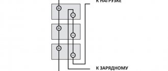
Series-parallel connection of power supplies
Who’s stopping you from connecting batteries or batteries simultaneously in series and in parallel? But is that really possible? Can). Using an example with water towers, it might look like this:
Here we see two towers, each of which consists of two turrets, and these two large towers are connected by a pipe.
Very often, a series-parallel connection is used in electric vehicles. I recently made a battery for my electric bike from li-ion 18650 batteries. My electric bike required a voltage of 36 Volts. So, now let's turn on the logic. One battery produces 3.6 Volts. To get 36 Volts, I need to connect 10 batteries in series.
To make it easier to understand, I will draw them not according to GOST:
Hooray! I got 36 volts for my electric bike. But the problem is that one such battery can deliver a current of 2800 milliamps to the load for 1 hour or 2.8 amperes for 1 hour. This parameter is indicated on batteries as mAh. I wrote about this in detail in this article “How to measure current and voltage with a multimeter.”
The fact that I connected all the batteries in series does not mean that their capacity has increased 10 times. Only the voltage increased 10 times, since I connected them in series . That is, the total amount turned out to be 36 Volts and the same 2800 mAh as for one battery.
Therefore, in order to increase the capacity, I must connect exactly the same branch of batteries in parallel to this branch, otherwise my electric bike will not travel even a couple of kilometers. I want to ride all day!
No sooner said than done. We connect another branch of 36 Volts. You haven't forgotten the rule that when connected in parallel, the voltage should be the same? As a result, we get something like this:
In total, we received the same notorious 36 Volts, but the capacity has doubled. 2800 mAh +2800 mAh = 5600 mAh. Well, with such a battery you can drive a little further. But this also seemed not enough to me, so I added 2 more branches. As a result, my homemade battery for an electric bicycle should schematically look like this: