The connection of resistors is the relative position of these elements in the circuit relative to each other and the power source. You can separately select serial and parallel connections of resistors. When both options are present in the circuit, then such a connection is called mixed.
We know that a resistor is an electronic component that has electrical resistance and power dissipation. If there are several resistors in a circuit, then to obtain the total resistance they resort to calculations according to the rules of series or parallel connection. In addition to the general resistance, groups of resistors, according to Ohm's law, affect the voltage and current in sections of the circuit. And in this review, the methodology for calculating the total resistance for various types of resistor connections will be discussed. An illustrative example with a mixed connection of resistors will also be considered, where in addition to resistances, voltages and current strength in different sections will be calculated.
It is worth immediately noting that in this topic the power dissipation of resistors is taken out of the brackets. Power is important when selecting and combining resistors in a circuit, but this is a separate topic. In addition, all the considered examples were taken taking into account a 220 V alternating voltage source. Why is this so? You will learn about this in the last paragraph of the publication.
Series connection of resistors
A series connection of resistors is such a mutual arrangement of components in which the current moves in one direction and has a common value for each resistor. With such a connection, the voltage at each section will be proportional to the resistance of a particular resistor in the circuit.
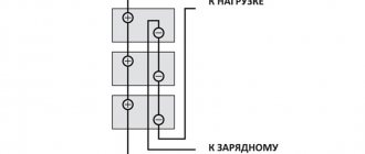
Schematic diagram of serial connection:
As you can see, there are three resistors connected in series in the circuit (there may be more). The resistance of the first resistor R1 = 20 Ohms. Second R2 = 70 Ohm. Third R3 = 10 Ohm.
To calculate the total (equivalent) resistance in a series connection, you need to add up all the nominal resistances of the resistors included in the circuit:
R = R1 + R2 + R3 + … + Rn.
R = 20 + 70 + 10 = 100 Ohm.
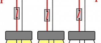
For clarity, the presented diagram shows the voltages in each of the three sections. And the voltage drop occurs depending on the resistance of a particular resistor. The current in the circuit is common to all resistors ( I = I1 = I2 = I3 ). Therefore, according to Ohm’s law, the current strength at a known power source voltage (in this case U = 220 V) is determined by the formula:
I = U / R = U / (R1 + R2 + R3 + … + Rn).
I = 220 / (20 + 70 + 10) = 220 / 100 = 2.2 A.
Formulas for finding the voltage on a section of a circuit with a known current strength (in this case I = I1 = I2 = I3 = 2.2 A):
- U1 = I × R1.
- U2 = I × R2.
- U3 = I × R3.
- Un = I × Rn.
Accordingly, U1 = 2.2 × 20 = 44 V; U2 = 2.2 × 70 = 154 V; U3 = 2.2 × 10 = 22 V. As a result, the sum of the potential differences across the resistors is equal to the total potential difference of the entire circuit (220 V).
The three resistors considered in a series circuit can be replaced with one with a resistance of 100 Ohms:
If you can replace several resistors with one, then a logical question arises why such a combination is used. In simple words, we can answer that sometimes it is impossible to select a resistor with the required parameters or it is necessary to create more complex electronic circuits. In this case, they resort to serial, parallel or mixed connection in the circuit.
In a chain of series-connected resistors, the main role is played by the one with the highest resistance. It is this that greatly influences the overall resistance. For example, if you connect three resistors with a nominal value of 1, 10 and 100 ohms, the result will be a composite resistor with a resistance of 111 ohms. If you remove the 100 ohm resistor, the total resistance of the chain drops sharply to 11 ohms. And if you remove the 10 ohm resistor, the resistance decreases slightly to 101 ohms.
What is the current power for series and parallel connection
The power of an individual resistive element is determined using the formula
P = U²/R or P = I²R, which can be derived from the formula for calculating the power of an electrical circuit P = UI according to Ohm’s law.
Parallel power
Having calculated the resistance of each element separately, we calculate the power of each using the formula P = I²R, where
- R is not the nominal resistance of the resistive element, but calculated for a given circuit;
- I – current strength in the circuit.
With a parallel connection, more current flows through a smaller resistor - the power dissipation on this resistive element will be greater than on the others.
Important! When calculating a parallel circuit, the power of the resistance with the smallest rating should be taken into account.
Power in series connection
Having calculated the resistance of each resistive element separately, we calculate the power of each using the formula P = U²/R, where
- R is the resistance we calculated for a specific circuit;
- U is the voltage drop across a given resistive element.
Help: The total power of a circuit in a series and parallel connection can be found by adding up the calculated powers of the individual elements included in the circuit Ptotal = P1+P2+P3+…+Pn.
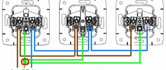
Parallel connection of resistors
A parallel connection of resistors is a mutual connection of components in which both terminals of one resistor are connected to the corresponding terminals of another resistor or resistors.
With this connection, the voltage in the entire circuit and in each section is the same and equal to the voltage of the power source U = U1 = U2 = U3 = Un . Each resistor carries its own current. The sum of the currents of all resistors gives the total current of the circuit: I = I1 + I2 + I3 + ... + In . Accordingly, the total conductivity of a parallel circuit is equal to the sum of its individual conductances. Conductivity is the reciprocal of resistance, so the equivalent resistance of resistors connected in parallel is determined by the following ratio:
1 / R = 1 / R1 + 1 / R2 + 1 / R3 + … + 1 / Rn . The reciprocal value of the total resistance of the circuit is equal to the sum of the reciprocal values of the resistances of parallel-connected conductors.
Let's calculate the total resistance for the above example with parallel connection of resistors:
1/R = 1/20 + 1/70 + 1/10 ≈ 0.164.
R ≈ 1 / 0.164 ≈ 6.097 Ohm.
For clarity, let’s simulate in the Electronics Workbench program the replacement of three parallel-connected resistors with one (R = 6.097 Ohm):
As you can see, the calculation was made correctly, since the current in the circuit with a 6.097 Ohm resistor is equal to the current in the parallel circuit (36.08 A ≈ 36.14 A).
Let us highlight the main features of parallel connection of resistors:
- The total resistance is always less than the resistance of any resistor connected in parallel.
- Increasing the number of resistors connected in parallel leads to a decrease in the total resistance and an increase in the total current in the circuit.
- If two resistors with the same resistance are connected in parallel, then the total resistance of these resistors will be exactly two times less than the resistance of each of the resistors included in this chain.
- If resistors of the same value are used in the circuit, then the formula for the total resistance is simplified and takes the form R = R1 / N (R1 is the nominal resistance of the resistor; N is the number of resistors with the same nominal resistance).
Solving problems on the topic:
By connecting conductors we mean connecting resistors - devices made based on the resistance of conductors. In previous lessons, parallel and serial connections were discussed. In this lesson, we will look at problems involving a mixed connection of conductors, that is, when the circuit contains both a series and a parallel connection.
To solve problems, first consider the formulas for relating various quantities in parallel and serial connections:
If the conductors are connected in series, then the current strength in them is the same and is equal to the current strength in the circuit. In this case, the total voltage in the circuit will consist of the sum of the voltages on each conductor. And if we talk about the resistance of this section of the circuit, in which the conductors are connected in series, then it is equal to the sum of the resistances of the conductors.
In a serial connection everything is different. The current strength in each branch of this circuit will be different, while the total current strength in the circuit will be calculated as the sum of the current strengths in the conductors. The voltage on conductors connected in series will be the same. The total resistance of this section of the circuit, the so-called “equivalent resistance” R, will be calculated using the following formula:.
It is also worth noting that a parallel connection is usually used when turning on household appliances, and a series connection is usually used to create a long, unbranched circuit.
Task No. 1
Let's consider the following problem. A section of the circuit consists of two series-connected resistances, each of which is equal to 1 ohm. Another resistance is connected in parallel to these two resistors, the value of which is 2 ohms. This entire circuit is connected to a current source, which creates a voltage of 2.4 V at the ends of this connection. It is necessary to determine the current strength in the entire electrical circuit (Fig. 1).
Rice. 1. Conditions and drawing of problem No. 1
As you can see, resistors R1 and R2 are connected in series, resistor R3 is connected in parallel to them. The source gives a voltage of 2.4 V, respectively, in section AB the voltage will also be 2.4 V. The current strength that needs to be found is the current flowing through ammeter A.
This connection of conductors is called unbranched. The industry usually makes a set of resistors with well-defined resistances, but any different resistances may be needed for experimentation. Then, using such circuits, you can create the required resistance for an experiment or device.
Next, you need to determine the equivalent resistance of the unbranched part. First, let's see what the resistance R' of the AB circuit section, which contains only resistors R1 and R2, is equal to. They are connected in series, then R′=R1+R2=2 [Ohm]. Now you can redraw the electrical circuit by replacing resistances R1 and R2 with their equivalent resistance R' (Fig. 2).
Rice. 2. First replacement with equivalent resistance
Now we can say that section AB includes not three, but two resistances: R3 and R'. These two resistances are connected in parallel, respectively, you can find the total resistance of the electrical circuit using the formula. Expressing R and substituting the values, we get:
It is worth noting that the resistances were connected, but the total resistance was still equal to 1 ohm. Now the electrical circuit can be replaced with the following (Fig. 3):
Rice. 3. Second replacement with equivalent resistance
In Fig. 3, resistance R=1 Ohm is called equivalent resistance, since three resistances have been replaced by one. To calculate the current in a circuit, you need to use Ohm's law for a section of the circuit: . The voltage across the resistance R is the voltage at section AB (Fig. 1), which, in turn, is equal to 2.4. Then . This will be the current value in the electrical circuit, which will be shown by the ammeter.
Mixed connection of resistors
Mixed resistor connection is a combination of series and parallel connection. This combination is sometimes called a series-parallel connection.
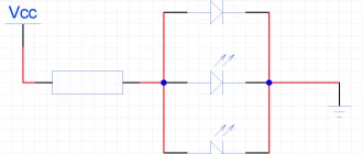
Example of a circuit with a mixed connection of resistors:
To calculate the equivalent resistance of such connections, the entire circuit is divided into the simplest sections and the following algorithm is followed:
| The total resistance of sections with parallel connection of resistors is determined. | |
| If these sections contain resistors connected in series, then their total resistance is first calculated. | |
| After intermediate calculations, the circuit is redrawn, and a circuit of equivalent resistances connected in series is obtained. | |
| Next, the resistance of the resulting simple circuit is calculated. |