What is a capacitor and its main characteristics
A capacitor is a radio component that works as a storage device for electrical energy. To make it clearer how it works, it can be thought of as a kind of small battery. Indicated by two parallel lines.
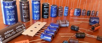
Designations of various types of capacitors in the diagrams. Most often, electrolytic capacitors fail, so it’s worth remembering their designation
The main characteristic of any type of capacitor is capacity. This is the amount of charge that it is able to accumulate. It is measured in Farads (abbreviated simply as the letter F or Ф), or rather, in smaller units:
- microfarads - µF is 10-6 farads,
- nanofarads - nF is 10-9 farads;
- picofarads - pF is 10-12 farads.
The second important characteristic is the rated voltage. This is the voltage at which long-term trouble-free operation is guaranteed. For example, 4700 uF 35 V, where 35 V is the nominal voltage of 35 volts.
For large capacitors, the capacitance and voltage are indicated on the case
You cannot place a capacitor in a circuit with a higher voltage than that indicated on it. Otherwise, it will quickly fail.
You can use 50 volt capacitors instead of 25 volt capacitors. But this is sometimes impractical, since those that are designed for higher voltage are more expensive, and their dimensions are larger.
Parallel and combined connection
There are other connection methods, namely combined and parallel connection of capacitors. Other physical laws apply to them.
Parallel capacitors
Capacitor energy
The voltage of the entire group when connecting capacitors in parallel is equal to the voltage of the smallest of them. That is, if there is a circuit of three capacitors for 16, 25 and 50 V, then the maximum that can be applied to them is 16 V. In such a circuit, the full voltage of the power source will be applied to each individual capacitor.
The capacity of such a battery is cumulative. This is caused by the virtual addition of the areas of the plates of all individual capacitors. In the language of physics it looks like this:
Ctotal par = C1 + C2 + … + Cn.
Why is such a connection needed? It is used to increase the capacitance of capacitors, for example, in the high-voltage part of welding inverters and many powerful power supplies.
Additional Information. A parallel connection allows you to reduce the overall internal resistance of the assembly, and therefore its heating. This way you can increase the service life of the container.
The combined (mixed) compound is the most complex. It contains both serial and parallel elements. Calculation of the parameters of such circuits is given with experience. For simplicity, it is customary to study it in a triangle, breaking it down into simpler parts.
Mixed compound
From the diagram it is obvious that capacitors C1 and C2 are connected in series. Their total capacity can be calculated using the formula described above - Ctotal last. Further the scheme is simplified. There are already two parallel capacitors Ctot.seq and C3. Calculated using the above formula Ctotal par. As a result, a difficult-to-understand circuit element turns into one equivalent capacitor. This technique describes a simplification algorithm with which you can calculate much more complex capacitor figures (square, cube, etc.).
Parallel connection of capacitors
Parallel connection of capacitors is a connection in which the capacitors are connected by both contacts. As a result, several capacitors can be connected to one point. When connected in parallel, one large capacitor is formed with a plate area equal to the sum of the plate areas of all individual components. Since the capacitance of capacitors is directly proportional to the area of the plates, the total capacitance Ctot in a parallel connection is equal to the sum of the capacitances of all capacitors in the circuit.
Parallel voltage
All capacitors connected in parallel receive the same voltage. This happens because there are only two points between which there can be a potential difference (voltage). In other words, we can say that with a parallel connection, all capacitors are connected to the same voltage source. The capacitor current during the transition period depends on its capacitance and voltage change:
- ic — capacitor current
- C - Capacitance of the capacitor
- ΔVC/Δt – Rate of voltage change
It will be interesting➡ How much do ceramic capacitors cost?
In a parallel connection, a separate current will flow through each capacitor, depending on the capacitance of the capacitor:
What is it and how does it work
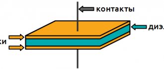
In the simplest case, a capacitor consists of two conductive plates (plates) separated by a dielectric layer.
Between the plates there is a layer of dielectric - a material that does not conduct electric current well.
The plates are supplied with direct or alternating current. At the beginning, while the energy is stored, the energy consumption of the capacitor is high. As the container “fills,” it decreases. When the charge is fully charged, there is no current consumption at all, the power source seems to turn off. At this time, the capacitor itself begins to release the accumulated charge. That is, it temporarily becomes a kind of power source. That's why it is compared to a battery.
Where and what are they used for?
As already mentioned, it is difficult to find a circuit without capacitors. They are used to solve a variety of problems:
- To smooth out surges in network voltage. In this case, they are placed at the input of devices, in front of microcircuits that are demanding on power parameters.
- To stabilize the output voltage of power supplies. In this case, you need to look for them before leaving.
Electrolytic cylindrical capacitors are often seen - Touch sensor (touch pads). In such devices, one of the “plates” of capacitors is a person. Or rather, his finger. Our body has a certain conductivity. This is what is used in touch sensors.
- To set the required rhythm of work. The charging time for capacitors of different capacities is different. In this case, the charge/discharge cycle of the capacitor remains constant. This is used in circuits where it is necessary to set a certain rhythm of work.
- Memory cells. The memory of computers, phones and other devices is a huge number of small capacitors. If it is charged, it is one, if it is discharged, it is zero.
- There are starting capacitors that help “accelerate” the engine. They accumulate a charge, then release it sharply, creating the required “push” to accelerate the motor.
- In photo flashes. The principle is the same. First, the charge is accumulated, then released, but converted into light.
Capacitors are common and their applications are wide. But you need to know how to connect them correctly.
Electrical capacity
When connecting devices for charge condensation, as a rule, the technician is interested in the electrical capacitance that will result.
Electrical capacity shows the ability of a two-terminal network to accumulate charge and is measured in farads. It may seem that the higher this value, the better, but in practice it is not possible to create all possible containers in the world, moreover, this is often not necessary, since all devices used every day use standard condensation devices.
You can connect several devices for condensation in a circuit, creating one condensing container, and the value of the characteristic value will depend on the type of connection, and there are long-known formulas for its calculation.
How to properly connect capacitors
To find out how to connect a capacitor correctly, you need to figure out exactly what type it is. There are a huge variety of these electronic devices. All capacitors are divided into two groups:
- polar (electrolytic) - when connecting them, it is necessary to take into account where the part has a positive and negative contact;
- non-polar (all others) - these capacitors are capable of operating on alternating current; they do not have positive and negative terminals.
Then you need to consider the design of the electronic component. From this point of view, capacitors can be:
- Inferential. They are connected to the board using thin copper legs, coated (tinned) with a layer of solder for protection.
- For surface mounting (SMD). Mainly used in compact electronics. Very miniature, often not exceeding 1 mm in diameter.
It is also important to take into account the operating voltage of the capacitor. This is especially important for electrolytic devices of this type, because if their rated voltage is exceeded, they will most likely explode, spraying boiling electrolyte in all directions.
Important! There are two notches on the cover of the electrolytic capacitor. These weak points serve to instantly depressurize the product in the event of excessive internal pressure. When repairing and adjusting equipment, avoid directing the notches onto your face or clothing. In an emergency, hot electrolyte may splash out from them.
The maximum voltage threshold is no less critical for other types of capacitors, especially those with small dimensions and unable to withstand overloads for a long time.
The last but not least important factor to consider when connecting capacitors is their capacitance. It is measured in microfarads (after Michael Faraday). This is their main characteristic, which is why capacitors are often called electrical capacitances. In some electronic devices, this parameter can deviate significantly, both downward and upward. In others, an error of 1% is unacceptable.
Design and operating principle
And one more very important point. Calculation of capacitor ratings Legend: Sp - starting, Wed - working. There are several options, but most often electricians install a capacitor in the circuit.
In some designs, a centrifugal switch is installed, which opens the contacts when a certain rotation speed is reached.
Next, knowing the operating voltage and the required capacity, we select capacitors according to the parameters: types and required quantity. Additionally, a phase shift can be obtained by using a starting phase with a higher resistance value and a lower inductance value.
Let's start with the fact that there are two standard schemes for connecting an electric motor to a three-phase network: star and triangle. Active resistors, inductors and capacitors can be used for this.
And one end of the starting winding, for one of the workers. Here, each winding is used for its own operating voltage, hence the power.
Determining pairs of wires belonging to one winding The second task, determining the beginning and end of the windings, is somewhat more complicated and requires a battery and a pointer voltmeter. However, in this case the rotation speed will decrease.
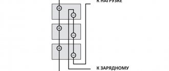
A phase is supplied to one terminal, zero to the other, and the capacitor group is switched on to the third. They even have labels that indicate that you can connect to both a three-phase network and a single-phase network. Connecting a capacitor. How to connect a capacitor to an electric motor. Scheme.
There is no capacitor of the required value: what to do
Very often, novice home craftsmen, having discovered a breakdown of the device, try to independently discover the cause. Having seen a burnt part, they try to find a similar one, and if this fails, they take the device for repair. In fact, it is not necessary that the indicators coincide. You can use smaller capacitors by connecting them in a circuit. The main thing is to do it right. In this case, 3 goals are achieved at once - the breakdown is eliminated, experience is gained, and family budget funds are saved.
Let's try to figure out what connection methods exist and what tasks the series and parallel connection of capacitors are designed for. Often it is impossible to do without connecting capacitors into a battery. The main thing is to do it right
How to connect capacitors
In electrical engineering there are two main types of connecting parts - parallel and series. Capacitors can also be connected using any of the above methods. There is also a special one - a bridge circuit. It has its own area of use.
The circuit can have series and parallel connection of capacitors
Parallel connection of capacitors
In a parallel connection, all capacitors are combined by two nodes. To connect capacitors in parallel, we twist their legs in pairs, crimp them with pliers, and then solder them. Some capacitors have large bodies (banks) and small terminals. In this case, we use wires (as in the figure below).
Connecting capacitors into a battery: methods of execution
There are 3 connection methods, each of which has its own specific purpose:
- Parallel - performed if it is necessary to increase the capacity while leaving the voltage at the same level.
- Consistent - the opposite effect. The voltage increases, the capacitance decreases.
- Mixed - both capacity and voltage increase.
Now let's look at each of the methods in more detail.
Parallel connection: diagrams, rules
It's actually quite simple. With a parallel connection, the calculation of the total capacitance can be calculated by simply adding all the capacitors. The final formula will look like this: Total = С₁ + С₂ + С₃ + … + Сn. In this case, the voltage on each of their elements will remain unchanged: Vtotal = V₁ = V₂ = V₃ = … = Vn.
It turns out that such an installation involves connecting all the capacitor plates to the power points. This method is the most common. But a situation may arise where it is important to increase the voltage. Let's figure out how to do this.
Serial connection: less commonly used method
When using the method of connecting capacitors in series, the voltage in the circuit increases. It consists of the voltage of all elements and looks like this: Vtot = V₁ + V₂ + V₃ +…+ Vn. In this case, the capacity changes in inverse proportion: 1/Comt = 1/С₁ + 1/С₂ + 1/С₃ + … + 1/Сn. Let's look at changes in capacitance and voltage when connected in series using an example.
Given: 3 capacitors with a voltage of 150 V and a capacity of 300 μF. Connecting them in series, we get:
- voltage: 150 + 150 + 150 = 450 V;
- capacity: 1/300 + 1/300 + 1/300 = 1/C = 299 uF.
This connection is made if there is a risk of breakdown of the capacitor dielectric when voltage is applied to the circuit. But there is another way of installation.
Good to know! Series and parallel connections of resistors and capacitors are also used. This is done in order to reduce the voltage supplied to the capacitor and prevent its breakdown. However, it should be borne in mind that the voltage must be sufficient to operate the device itself.
Mixed connection of capacitors: diagram, reasons for the need for use
This connection (also called series-parallel) is used if it is necessary to increase both capacity and voltage. Here, calculating the general parameters is a little more complicated, but not so much that it is impossible for a novice radio amateur to figure it out.
Let's create a calculation algorithm.
- the entire circuit needs to be divided into separate parts, the parameters of which are easy to calculate;
- calculate denominations;
- We calculate the general indicators, as with sequential switching.
Parallel and series connection of capacitors
Circuit elements can be connected in two ways:
Let us illustrate these connections using the example of two capacitors (Fig. 1).
series connection of capacitors
Rice. 1. Series connection of capacitors
Logical charging of capacitors occurs as shown in Fig. 1. Coming from the circuit, the electron stops on the left plate (plate) of the capacitor. At the same time, thanks to its electric field (electrification through influence), it knocks out another electron from the right plate, which goes further into the circuit (Fig. 1.1). This resulting electron goes to the left plate of the next capacitor connected in series. And everything repeats itself again. Thus, as a result of the “passage” of “one” electron through a series chain of capacitors, we obtain a charged system with charges of equal value on each of the capacitors (Fig. 1.2).
In addition, the voltage on a series-connected bank of capacitors is the sum of the voltages on each of the elements (analogous to the series resistance of the conductors).
Rice. 2. Series connection of capacitors
Part of the tasks of school physics concerns the search for the total electrical capacity of a section of a circuit; the logic of such a search is: find such an electrical capacity that can be used to replace the circuit so that the voltage and charge parameters remain unchanged (Fig. 2). Let the charge on both capacitors be (remember that they are the same), the electrical capacitances be , and the corresponding voltages be and .
- where is the voltage across the first capacitor,
- - electrical capacity of the first capacitor,
- - capacitor charge.
- where is the voltage across the second capacitor,
- - electrical capacity of the second capacitor,
- - capacitor charge.
- where is the voltage of the full circuit,
- - electrical capacity of the common capacitor,
- - charge of the common capacitor.
Keeping in mind that the capacitors are connected in series, we get:
Or in general:
- where is the electrical capacity of series-connected capacitors,
- - the sum of the return capacities.
For a circuit of two serial connections:
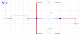
parallel connection of capacitors
Rice. 3. Parallel connection of capacitors
The parallel connection of capacitors is shown in Figure 3. When introducing an electron into the system, it has the choice of going to the top or bottom capacitor. With a large number of electrons, the filling of the capacitor plates occurs in direct proportion to the electrical capacity of the capacitors.
Rice. 4. Parallel connection of capacitors. Search for total electrical capacity
Let's try again to solve the problem of finding the total capacitance of the capacitors (Fig. 4). We remember that when connected in parallel, the voltages on the elements are the same, then:
- where is the charge on the first capacitor,
- - electrical capacity of the first capacitor,
- — voltage on the first capacitor.
- where is the charge on the second capacitor,
- - electrical capacity of the second capacitor,
- — voltage on the second capacitor.
- where is the charge on the common capacitor,
- - electrical capacity of a full capacitor,
- - voltage across the common capacitor.
Taking into account that , we get:
Or in general:
- where is the electrical capacity of parallel-connected capacitors,
- - the sum of the electrical capacities of a series-connected circuit.
Conclusion: in problems in which a circuit is present, it is necessary to consider which specific connection is being considered, and then use the appropriate logic of reasoning:
- for a series connection, the charges of all capacitors are the same: .
- the voltage in the entire circuit is the sum of the voltages on each of the elements: ,
- The total electrical capacity of a chain of capacitors connected in series is equal to: .
- the charge of a system of capacitors is the sum of the charges on each of them: ,
We advise you to study Checking the voltage in the outlet
Current when capacitors are connected in series
Electric current is of two types: direct and alternating. This is of great importance for the operation of containers.
Capacitor and DC
Marking of tantalum SMD capacitors
No direct current passes through the capacitor at all. This is also true for a line of series-connected containers. This effect is again explained by the design of the electronic device itself. The capacitor has two metal plates. In simple electrolytic devices they are made of aluminum foil. Between them there is a thin layer of dielectric (aluminum oxide). If a potential difference (voltage) is applied to the plates, current will flow, but only for a very short time until the capacitor is fully charged. Further, the movement of charge carriers will stop, because they will not be able to pass through the dielectric. At this moment we can say that the electric current is zero, and the capacitor does not allow it to pass through.
Capacitor and alternating current
With alternating current, charge carriers periodically change their direction. In the case of a household network, the change occurs 50 times per second. Therefore, they say that the frequency of the current in the socket is 50 Hz.
Important! Capacitors are able to accumulate and hold a charge for a long time. When working with containers charged from a 220 V network, they should always be discharged with a resistance of 100-1000 ohms. Failure to follow the rule will one day result in an unpleasant electric shock.
The capacitor will definitely pass alternating current, but not necessarily all of it. The number of charge carriers that can pass through this electronic device depends on the capacitance of the capacitor, the voltage applied to it and the frequency of changes in the direction of charges. Mathematically this is expressed as follows:
I = 2pfCU.
Here I is an electric current with frequency f passing through a capacitor of capacitance C, if a voltage U is applied to its plates. 2 is just a number, and p = 3.14.
This ability of capacitors to limit alternating current is widely used in audio engineering to build various sound filters. By changing the capacitance, you can influence the signal frequency that it transmits.
Capacitance based filter
Mixed connection of capacitors
A mixed connection (series-parallel) of capacitors is used when it is necessary to increase the capacity and operating voltage of the capacitor bank.
Let's look at the mixed connection of capacitors using the examples below.
Capacitor Energy
where Q
- charge of the capacitor or capacitors to which voltage
U ;
C is the electrical capacitance of a capacitor or battery of connected capacitors to which voltage
U .
Thus, capacitors serve to accumulate and store the electric field and its energy.
15. Define the concepts of three-ray star and triangle of resistance.
Write down the formulas for converting a three-ray star of resistance into a triangle of resistance and vice versa.
Convert the circuit to two nodes (Figure 5) Figure 5 - Electrical circuit
6.EXCHANGE DIAGRAMS
To facilitate the calculation, an equivalent circuit of the electrical circuit is drawn up, i.e., a circuit that displays the properties of the circuit under certain conditions.
The equivalent circuit shows all the elements whose influence on the calculation result cannot be neglected, and also indicates the electrical connections between them that are present in the circuit.
1. Replacement diagrams for electrical circuit elements
In calculation diagrams, the energy source can be represented by an EMF without internal resistance, if this resistance is small compared to the resistance of the receiver (Fig. 3.13.6).
When r = 0 internal voltage drop Uо = 0, therefore
the voltage at the source terminals at any current is equal to
EMF: U = E =
const.
In some cases, the source of electrical energy in the design diagram is replaced by another (equivalent) circuit (Fig. 3.14, a),
where instead of EMF
E,
the source is characterized by its short circuit current IK, and instead of internal resistance, internal conductivity
g = 1/ r .
We advise you to study Homemade television antenna: for dvb and analog signal
The possibility of such a replacement can be proven by dividing equality (3.1) by r:
U r =
E r - I ,
where U r =
Io
is a certain current equal to the ratio of the voltage at the source terminals to the internal resistance;
E r = I K
- source short circuit current;
Introducing new notations, we obtain the equality I K =
Io + I ,
which is satisfied by the equivalent circuit in Fig.
3.14, a.
In this case, for any voltage at the terminals; source, its current remains equal to the short circuit current (Fig. 3.14.6):
I=Iк=const.
A source with a constant current that does not depend on external resistance is called a current source.
The same source of electrical energy can be replaced in the design circuit by an EMF source or a current source.
Laws of series and parallel connection of conductors
For a detailed understanding in practice of both types of connections, we present formulas explaining the laws of these types of connections. Power calculations for parallel and series connections are different.
In a series circuit, there is the same current in all conductors:
I = I1 = I2.
According to Ohm's law, these types of conductor connections are explained differently in different cases. So, in the case of a series circuit, the voltages are equal to each other:
U1 = IR1, U2 = IR2.
In addition, the total voltage is equal to the sum of the voltages of the individual conductors:
U = U1 + U2 = I(R1 + R2) = IR.
The total resistance of an electrical circuit is calculated as the sum of the active resistances of all conductors, regardless of their number.
In the case of a parallel circuit, the total voltage of the circuit is similar to the voltage of the individual elements:
U1 = U2 = U.
And the total strength of the electric current is calculated as the sum of the currents that exist in all conductors located in parallel:
I = I1 + I2.
To ensure maximum efficiency of electrical networks, it is necessary to understand the essence of both types of connections and apply them expediently, using the laws and calculating the rationality of practical implementation.
Mixed connection of conductors
Series and parallel resistance circuits can be combined in one electrical circuit if necessary. For example, it is possible to connect parallel resistors in a series circuit to another resistor or group of resistors; this type is considered combined or mixed.
In this case, the total resistance is calculated by summing the values for the parallel connection in the system and for the series connection. First, it is necessary to calculate the equivalent resistances of resistors in a series circuit, and then the elements of a parallel circuit. Serial connection is considered a priority, and circuits of this combined type are often used in household appliances and appliances.
So, by considering the types of conductor connections in electrical circuits and based on the laws of their functioning, you can fully understand the essence of the organization of circuits of most household electrical appliances. For parallel and series connections, the calculation of resistance and current is different. Knowing the principles of calculation and formulas, you can competently use each type of circuit organization to connect elements in the optimal way and with maximum efficiency.
Mixed connection
But, it is worth considering that to connect different capacitors, it is necessary to take into account the network voltage. For each semiconductor, this indicator will differ depending on the capacitance of the element. It follows that individual groups of small-capacity semiconductor biterminals will become larger when charging, and vice versa, a large-sized electrical capacitance will require less charging.
Scheme: mixed connection of capacitors
There is also a mixed connection of two or more capacitors. Here, electrical energy is distributed simultaneously using parallel and series connections of electrolytic cells in a circuit. This circuit has several sections with different connections of condensing two-terminal networks. In other words, on one the circuit is connected in parallel, on the other - in series. This electrical circuit has a number of advantages compared to traditional ones:
- Can be used for any purpose: connecting an electric motor, machine equipment, radio equipment;
- Simple calculation. For installation, the entire circuit is divided into separate sections of the circuit, which are calculated separately;
- The properties of the components do not change regardless of changes in the electromagnetic field or current strength. This is very important when working with opposite two-terminal networks. The capacitance is constant at a constant voltage, but the potential is proportional to the charge;
- If you need to assemble several non-polar semiconductor two-terminal networks from polar ones, then you need to take several single-pole two-terminal networks and connect them in a back-to-back (triangle) manner. Minus to minus, and plus to plus. Thus, by increasing the capacitance, the operating principle of a bipolar semiconductor changes.
How to check the quality of connection of capacitors in a circuit
The most ideal case is when we have an appropriate type of voltmeter on hand. It costs around one thousand rubles.
This is not so much, considering that together we get a device for measuring resistance, direct and alternating voltage, and currents.
The socket for measuring the capacitor (see photo on the left) consists of two narrow slots into which the legs should be inserted.
According to our observations, there is no difference which side to insert the electrolytic capacitor. Although it is better to follow the instruction manual.
Then you need to somehow mark them, or lay them out according to a diagram drawn on paper, where you can put all the numbers (by the way, this is usually done in all Chinese technology).
Then you should calculate using the formulas exactly what value should be obtained and check it with a tester. Does not work? This means that the quality of the contacts is poor - use less twisting.
CAPACITOR CONNECTIONS
If it is necessary to increase the total capacitance of the capacitors, then they are connected to each other in parallel (Fig. 9, a
). With this connection method, the total area of the plates increases compared to the plate area of each capacitor. The total capacitance of capacitors connected in parallel is equal to the sum of the capacitances of the individual capacitors and is calculated by the formula Ctot = C1 + C2 + C3+
(10)
This can be confirmed as follows.
Capacitors connected in parallel are under the same voltage, equal to U volts, and the total charge of these capacitors is equal to q coulombs. In this case, each capacitor respectively receives a charge q 1, q 2, q 3, etc. Therefore,
q total = q 1 + q 2 + q 3 +
From formula (8) it follows that the charge
qtot = Ctot U (11)
and charges q 1 = C 1 U; q 2 = C 2 U; q 3 = C 3 U.
Substituting these expressions into formula (11), we obtain:
C total U= C 1 U + C 2 U + C 3 U.
Dividing the left and right sides of this equality by the value U equal for all capacitors, after reduction we find:
C total = C 1 + C 2 + C 3
Example
. Three capacitors with a capacity C 1 = 2 μF; C 2 =0.1 µF and C 3 =0.5 µF are connected in parallel.
Calculate their total capacity.
C total = C 1 + C 2 + C 3 = 2 + 00.1 + 0.5 = 2.6 μF.
The total capacitance of capacitors having the same capacitance and connected in parallel can be calculated using the formula
Ctot = Cn, (12)
where C is the capacitance of one capacitor,
n is the number of capacitors.
Example.
Five capacitors with a capacity of 2 μF each are connected in parallel. Determine their total capacity.
C total = Cn = 2·5 = 10 μF.
Capacitors are connected in series (Fig. 9, b) when the operating voltage of the installation exceeds the voltage for which the insulation of one capacitor is designed. In this case, the right plate of the first capacitor is connected to the left plate of the second, the right plate of the second to the left plate of the third, etc. The total capacitance of the capacitors with this connection decreases. The reciprocal of the total capacitance of capacitors connected in series is equal to the sum of the reciprocals of the capacitances of individual capacitors:
This can be confirmed as follows. The total voltage on the capacitors U is the total on each capacitor U 1, U 2, U 3, then
U total = U 1 + U 2 + U 3.
From Formula (8) it follows that the voltage
U total = (14)
and the voltage
Substituting these expressions into formula (14), we obtain:
Let us divide the left and right sides of this equality by the value q and after reduction we find:
Example. Three capacitors C1=2 µF, C2=4 µF and C3=8 µF are connected in series. Determine their total capacity.
If capacitors having the same capacitance are connected in series, then their total capacitance can be calculated using the formula
Example.
Four capacitors with a capacity of 1000 pf each are connected in series. Determine their total capacity. Solution.
If two capacitors of different capacitance are connected in series, then their total capacitance can be found using the formula
Example.
Two capacitors C 1 =200 pF
and C 2 =300 pf connected in series. Calculate their total capacity.
As can be seen from the above examples, the total capacitance of capacitors connected in series is always less than the smallest capacitance included in the connection.
Capacitors are selected according to their capacitance and the operating voltage that is supplied to its plates when connected to the circuit. When the voltage exceeds the permissible value, a breakdown of the dielectric in the capacitor occurs. This voltage is called breakdown voltage. The breakdown of the dielectric is accompanied by an electrical discharge - a spark with a characteristic crackling sound. A capacitor with a broken dielectric is not suitable for use.
Each dielectric has a certain electrical strength, i.e., the ability to resist breakdown. Electrical strength (Table 2) is usually measured in (v/cm
) and is determined by the formula
where U is voltage, V
d—dielectric thickness, cm.
Many people, when assembling a particular device, often think about how to connect capacitors in a parallel or series connection. Not every denomination is produced by industry, so the task of providing a design with a bunch of containers occurs here and there. When connected in parallel, the denominations are added, and when connected in series, a more complex formula is used. There are also tuning capacitors; these are definitely included in circuits where it is necessary to provide the necessary resonant characteristics. In this case, it is also necessary to solve the above problem. The problem is that often the assembly of some kind of induction heater is literally done on your knees, there is a whole pile of iron, there are no pads at hand, and you are too lazy to solder - what to do?
Series connection of capacitors.
If the connection of capacitors into a battery is made in the form of a chain and the plates of only the first and last capacitors are directly connected to the connection points in the circuit, then such a connection of capacitors is called serial ( Figure 3).
Figure 2. Series connection of capacitors.
When connected in series, all capacitors are charged with the same amount of electricity, since only the outer plates (1 and 6) are charged directly from the current source, and the remaining plates (2, 3, 4 and 5) are charged through influence. In this case, the charge of plate 2 will be equal in magnitude and opposite in sign to the charge of plate 1, the charge of plate 3 will be equal in magnitude and opposite in sign to the charge of plate 2, etc.
The voltages on different capacitors will, generally speaking, be different, since charging capacitors of different capacities with the same amount of electricity always requires different voltages. The smaller the capacitance of the capacitor, the greater the voltage required in order to charge this capacitor with the required amount of electricity, and vice versa.
Thus, when charging a group of capacitors connected in series, the voltages on small capacitors will be greater, and on large capacitors - less.
Similar to the previous case, we can consider the entire group of capacitors connected in series as one equivalent capacitor, between the plates of which there is a voltage equal to the sum of the voltages on all capacitors of the group, and the charge of which is equal to the charge of any of the capacitors of the group.
Let's take the smallest capacitor in the group. There should be the greatest tension on it. But the voltage across this capacitor is only a fraction of the total voltage that exists across the entire group of capacitors. The voltage across the entire group is greater than the voltage across the capacitor with the smallest capacitance. And from here it directly follows that the total capacitance of a group of capacitors connected in series is less than the capacitance of the smallest capacitor in the group.
To calculate the total capacitance when connecting capacitors in series, it is most convenient to use the following formula:
For the special case of two series-connected capacitors, the formula for calculating their total capacitance will be:
Comparison of different options
| Capacity | Voltage | |
| Parallel | Increases | Doesn't change |
| Sequential | Decreases | Increases |
| Mixed | Changes | Increases |
To select a connection, you can use the following table. On the left is the type of connection of devices, on top is the properties of the device for charge condensation.
If you need to increase the capacity, then you need to use a parallel connection, and if you increase the voltage, then a serial connection. If both are required, then it will be necessary to calculate the mixed connection of capacitors in the circuit.