About the capacitor
This device has the ability to store electrical charge. Between its plates is a dielectric layer that creates insulation for a pair of conductive surfaces. The main characteristic of the device is capacity - the ability to accumulate charge. In terms of technology, the most common types of capacitors are electrolytic and electrostatic. The choice of element used depends on the characteristics of the electrical circuit and what function it should perform.
The device of a simple capacitor
The capacitor consists of two metal plates - electrodes, also called plates, between which there is a thin layer of dielectric.
Actually, all capacitors are designed in exactly this (or almost this) way, except that the material of the plates and dielectric changes.
To increase the capacitance of a capacitor without increasing its size, various tricks are used. For example, if we take two covers in the form of long strips of foil, put at least the same polyethylene between them and roll it all up like a roll, we will get a very compact device with a large capacity. This is exactly how film capacitors are designed.
If instead of polyethylene you take paper and impregnate it with an electrolyte, then a thin layer of oxide will form on the surface of the foil, which does not conduct current. Such a capacitor will be called electrolytic.
There are many different types of capacitors: paper, film, aluminum oxide and tantalum, vacuum, etc. In our tutorial we will use oxide electrolytic capacitors due to their high capacity and availability.
Capacitor symbols
Electric current power
In Russia, there is a system of conventional graphic symbols, including the UGO of the capacitor. A separate GOST, which is part of the Unified System of Design Documentation, is dedicated to the visual representation of these devices, as well as resistors. International standards – IEEE – are also used.
Constant capacitor
Such elements are produced with and without polarization. Small non-polarized products have a wide range of applications and can be connected in different directions. In the diagram they are indicated by two parallel short lines located at right angles to the connection lines. The device’s casing indicates its capacity, often without units of measurement (0.1 is 1 microfarad).
Important! Abroad, the abbreviation MFD is sometimes used to indicate capacity. It means microfarads.
Graphic representation of an element with constant capacity
Capacitor number code
The first pair of characters shows the capacity, the number after them shows the number of zeros. The unit of measurement is picofarad. Sometimes such markings contain letters; they indicate the percentage tolerance and the rated voltage.
Polarized capacitors
The most common type of polar capacitor element is electrolytic. Such products are produced in the form of cylinders or in axial design. The first option is somewhat more compact and cheaper. Its terminals are located on one side, while the axial options are on different sides. Since the devices are relatively large, the rated voltage (it is relatively low) and capacitance are indicated on their cases.
Important! When connecting these products, the polarity must be strictly observed, otherwise they may malfunction or even explode.
This is how polarized elements are shown in diagrams
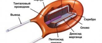
Tantalum capacitors
These products are extremely compact; they are used in cases where it is important to minimize dimensions. In the past, they were marked with two colored stripes (each color corresponding to a number) and a speck of white or gray (in the first case, the microfarad value of the stripes was divided by 10, in the second by 100). If you turn the object with the spot facing you, there will be a plus pole on the right side. A stripe indicating voltage was also drawn near the terminals. Modern models are marked with digital parameter values.
Variable capacitors
Due to the very low capacitance, these parts have a narrow scope of application - they are mainly used in radio circuits. Graphically, variable elements are represented by the traditional symbol of a pair of short parallels crossed out with an inclined arrow. Capacity is indicated not by a clear number, but by a range.
Designation of variable products
Capacitor trimmers
These are superminiature products mounted directly on a printed circuit board. Since the capacity indicator changes only during adjustment work, such elements are called tuning elements. The graphical representation differs from the standard one for variable capacitors only in that instead of a point, the arrow is equipped with a perpendicular dash.
Ionistor
This product has a two-layer structure and a fairly large capacity (up to 10 F). At the interface of the electrode surface and electrolyte in such devices, a space of static charge carriers appears. Unlike electrolytic variations, the method of storing energy here is an electrostatic field. The combination of a large surface area and a small thickness of space provides such a high capacity value. Denoted as a symbol of a capacitor element with a vertical line perpendicular to it, placed in a circle. At the same time, in the upper right and lower left quarters, into which the symbol and vertical divide the circle, there are lines similar to the graph of a half-sine wave.
Capacitors | Operating principle and marking of capacitors
Capacitors perform many useful functions in electronic device circuits despite their simple design. If you disassemble several radio-electronic devices to detail and count them, it turns out that the number of elements discussed in this article will exceed the number of other individual radio-electronic devices, including resistors. In view of this circumstance, we should pay special attention to the design, structure and principle of operation of capacitors.
Operating principle of a capacitor
To better understand the principle of operation of a capacitor, consider its design. The simplest capacitor consists of two metal plates called plates. Between the plates there is a dielectric, that is, a substance that practically does not allow electric current to pass through. The covers, as a rule, have the same geometric dimensions (square, rectangle, circle) and are equal in area. The plates are made of aluminum, copper or precious metals. The presence of precious metals in the composition of the plates causes an increased hunt on radio markets for Soviet samples of this radio-electronic element.
Dry paper, ceramics, porcelain, air, etc. are used as a dielectric located between the plates.
The principle of operation of a capacitor is as follows. If one plate is connected to the plus of an electric current source, and the second to the minus, then both plates will be charged with opposite charges. Charges will continue to be held on the plates even after the power source is disconnected. This is explained by the fact that charges of different signs (“+” and “-”) tend to attract each other. However, this is prevented by a dielectric (material that does not conduct charges) located in their path. Therefore, the charges distributed over the entire area of the plates remain in their places and are held by forces of mutual attraction.
Dielectric polarization
This phenomenon is called the accumulation of electrical charges. And a capacitor is called an electric field accumulator, since an electric field acts around each charge, under the influence of which the dielectric is polarized, that is, its molecules become polar - they have clearly defined positive and negative poles. The poles of the molecules of a non-conducting substance are oriented along the lines of the electric field created by the charges located on the plates. Moreover, the negative pole of the molecule is directed towards the positive plate, and the positive pole - towards the negative one.
The ability to accumulate electrical charges is characterized by the capacitance of the capacitor, hence its designation on the drawings of electrical circuits C (English: apacitor - accumulator). Similar to the capacity of a vessel - the larger the capacity of the vessel, the more liquid it can hold.
The capacitance of a capacitor refers to the main parameter and is measured in farads [ F ], named after the outstanding English physicist Michael Faraday.
Please note: it is correct to say not “one farad”, but “one farad”.
A capacitor has a capacitance of one farad, which accumulates a charge of one coulomb if a voltage of one volt is applied to the plates.
Previously, one could often hear the statement that a capacity of 1 F is a lot - almost the capacity of our planet. However, now, with the advent of supercapacitors, they no longer say this, since the capacity of the latter reaches hundreds of farads. However, most electronic circuits use drives smaller than C —picofarads, nanofarads, and microfarads.
Capacitor capacitance calculation
Calculating the capacitance of capacitors is quite simple. It is determined by three parameters: plate area S , distance between plates d and dielectric type ε :
The physical meaning of this formula is as follows: the larger the area of the plates, the more charges can be located (accumulated) on it; The greater the distance between the plates and, accordingly, between the charges, the lower the force of their mutual attraction - the weaker they are held on the plates, so it is easier for the charges to leave the plates, which leads to a decrease in their number, and therefore a decrease in the capacity of the electric field storage device.
Dielectric constant ε shows how many times the charge of a capacitor with a given dielectric exceeds the charge of a similar storage device if there is a vacuum between its plates of the same area and located at the same distance. For air, ε is equal to unity, that is, practically no different from vacuum. Dry paper has a dielectric constant twice that of air; porcelain - four and a half times ε = 4.5. Capacitor ceramics have ε = 10..200 units.
An important conclusion follows from this: in order to obtain maximum capacity while maintaining the same geometric dimensions, a dielectric with maximum dielectric constant should be used. Therefore, ceramics are used in widely used flat-plate capacitors.
Capacitor in DC and AC circuits
Since there is a dielectric between the plates of the capacitor, electric current cannot flow from one plate to another, therefore, an open circuit is formed for direct and alternating current. Therefore, we can confidently say that the capacitor does not allow direct current to pass through! It also does not allow alternating current to pass through, but the alternating current constantly recharges the storage device, which creates the picture of alternating current passing through the plates of the capacitor.
If a constant voltage is applied to the plates of a discharged capacitor, an electric current will begin to flow in the circuit. As it charges, the current will decrease and if the voltages on the plates and the power source are equal, the current will stop flowing - a break in the electrical circuit will form.
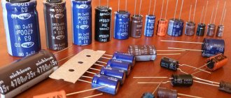
Fixed capacitors
The capacity of such capacitors is not intended to be changed during the operation of radio-electronic equipment. They are distinguished by the widest variety and geometric sizes - from a match head to huge cabinets and are most widely used in printed circuit boards of electronic devices. The most common specimens are shown in the photo.
Variable capacitors KPE
To change the capacitance of a separate unit of an electrical circuit directly during operation of an electronic device, variable capacitors (VCA) are used. KPIs were mainly used in old-style receivers to tune the oscillating circuit to the resonant frequency of the radio station. However, now, instead of KPIs, varicaps are used - semiconductor diodes, the capacitance of which is determined by the value of the supplied reverse voltage. Now it is enough to change the voltage supplied to the varicap to change the capacitance of the latter, and as a result, the frequency of the oscillatory circuit.
As a rule, KPI consists of a number of parallel metal plates separated by air, so their dimensions are very significant. Varicaps, on the contrary, have much smaller dimensions, which is why they replaced the KPE.
Trimmer capacitors
Trimmer capacitors are used in final tuning units of electronic equipment. Most often they are found in various kinds of oscillatory circuits or in devices related to frequency formation; in measuring instruments. They can also be found in digital oscilloscope probes. There they are used to eliminate the intrinsic capacitance of the measuring probes, which makes it possible to eliminate errors as much as possible when performing measurements of high-frequency signals.
Electrolytic capacitors
The main difference and advantage of electrolytic capacitors is their large capacity with small dimensions. Due to this property, they are widely used as electrical filters to smooth out rectified voltage, which makes them an integral part of any power supply.
Structurally, the electrolytic capacitor is made of aluminum foil, which serves as one of the plates. The foil is wound into a roll in the form of a cylinder, which allows you to increase the active area of the lining. An oxide layer is applied to the foil, which is a dielectric. The second plate is an electrolyte or semiconductor layer. For this reason, electrolytic capacitors are polar (non-polar ones are used much less frequently), that is, polarity must be observed when connecting them to the circuit. Otherwise, it will fail, most often it will explode. Therefore, you should be extremely careful when connecting such a radio-electronic element to an electrical circuit, which is often forgotten to do when replacing this component.
The negative terminal of the new electrolytic capacitor is shorter than the positive one, and the corresponding minus sign is applied to the housing next to it. In Soviet marking, on the contrary, the positive terminal is marked, on the side of which a “+” sign is applied to the housing.
Also, the housings of electrolytic capacitors must contain the values of three main parameters: nominal capacitance value , maximum permissible voltage and maximum operating temperature .
If everything is clear with the capacity and permissible temperature, then special attention should be paid to the voltage.
An electrolytic capacitor must not be supplied with a voltage greater than that indicated on the housing . Otherwise it will explode. Most developers of electronic equipment advise not to exceed the voltage on the plates more than 80% of the permissible value.
Designation of capacitors in circuits
In electrical diagram drawings, the designation of capacitors is strictly standardized. However, this radio-electronic element can always be recognized in the circuit by two parallel, adjacent vertical lines. Two vertical lines indicate two facings. These dashes are signed with the Latin letter C , next to which the serial number of the element in the circuit is indicated, and below or on the side the capacitance value in microfarads or picofarads is indicated.
Capacitor markings
As electronics develops, so does the element base. Since many countries produce their own radio-electronic elements, their markings differ from the markings of radio-electronic elements in other countries. Therefore, in the first stages of industrial electronics production, many different types of marking were used, but the desire for unification led to more or less streamlining. This made it possible to bring the marking of capacitors to general rules. And the advantage here is obvious - a radio-electronic element produced in one country can now quite easily be matched with an analogue produced in another country. It would be ideal to reduce all types of designations and markings to a single type, which has already been almost completely accomplished.
However, Soviet capacitors, distinguished by a small but varied marking, are still in wide circulation. Everything was involved in Soviet markings - numbers, letters and colors. Moreover, both numbers and letters, as well as colors, numbers and letters, were applied to the housings of the elements. The numbers indicate the value, the letters indicate the units of measurement.
The more common type of marking consists of numbers that indicate the capacity in picofarads , not to be confused with farads! You should always remember that, unlike resistors, which are marked in ohms, the basic dimension, regardless of the marking method, is picofarads (if the numbers are separated by a comma, then microfarads ). In general, capacitance starts from picofarads .
Also, previously only color marking was used - a solid color with a colored dot. The parameters can only be determined using the reference book.
The types of markings discussed above are gradually going out of use, but they are always remembered by specialists who repair Soviet equipment in which radioelements have the “old” designation.
The most successful and perfect way to designate electronic elements is digital coding. Digital coding of capacitors, like resistors, involves the use of only three digits. This approach allows for many combinations to be implemented. The two digits on the left indicate the mantissa, that is, the significant number, and the last - third digit shows how many zeros need to be added to the previous two digits. 153 is indicated on the drive case , then its capacity is 15 × 10 3 = 15000 pF = 15 nF = 0.015 μF.
In addition to capacity, drives are characterized by a number of basic parameters, which are discussed below.
Marking of SMD capacitors
The marking of SMD capacitors can be applied to the case in the form of digital coding, but in the vast majority it is a somewhat confusing encryption consisting of one or two letters of the Latin alphabet. If there are two letters, then the first one indicates the manufacturer, which interests us to a lesser extent. But the second or only letter denotes the mantissa, in the same way as in digital coding. The remaining digit shows the number of zeros after the mantissa. You can decipher the digital value of a letter using the table below.
SMD drives with similar characteristics also differ in size. A number of standard sizes are shown in the table and figure below. It is especially important to take into account the dimensions of radio-electronic elements when designing printed circuit boards.
The marking of electrolytic SMD capacitors is practically no different from their output counterparts. A negative pad is indicated by a black mark on the flat side of the housing on the side of the corresponding pad. The permissible voltage in volts and capacitance in microfarads are also indicated.
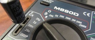
Quite often there are cases that do not have any markings on them. Only a capacitance meter can help here.
Series connection of capacitors
Connecting capacitors in series allows you to apply a higher voltage to their plates than to a separate storage device. The voltage on the plates is distributed depending on the capacitance of the element.
If two drives have the same capacity, then the supplied voltage is distributed equally between them. However, the total capacity will be half that of a separate drive.
In general, the rule to remember is that when capacitors are connected in series together, they can withstand higher voltages, but this comes at the cost of reduced capacitance.
Parallel connection of capacitors
This connection method is the most common in practical applications, since the capacity of one drive is not always enough, especially in electrical filters of high-quality power supplies. Parallel connection of capacitors realizes the summation of the capacitances of individual storage devices. This is quite easy to remember, based on the formula above, which shows that as the area of the plates increases, the capacitance increases.
Therefore, when connecting capacitors in parallel, there is a kind of increase in the area of the plates, due to which they are able to accumulate a larger number of electrical charges.
The main parameters and ratings of capacitors are discussed here.
More articles on this topic
- Zener diode | Operating principle and marking of zener diodes
- Characteristics of capacitors
- RESISTORS | Resistor markings
- Proteus | Simulation of microcontroller operation
Marking of domestic capacitors
Post-Soviet manufacturers label their products in quite detail and in a unified manner. In rare cases, there may be some differences in the designations.
Capacity
This parameter is always specified first; for fractional numbers its encoding consists of three characters. The first digit is the integer part of the number reflecting the value of the capacitance, the third is the fractional part, the second position is a letter indicating the unit of measurement: m - millifarad, n - nanofarad, p - picofarad. For example, 3n6 is 3.6 nanofarads. Integer values are indicated as follows: a number and next to it a unit of measurement with the added letter F (3 pF - 3 picofarads).
Important! If the denomination is not indicated, the whole number indicates that the value was indicated in picofarads, the decimal fraction - in microfarads.
Rated voltage
If the size of the product is sufficient, the indicator is indicated according to the standard scheme: 180 V (or V) - 180 volts. On miniature capacitors, the value is coded with a Latin letter, for example, 160 V - with the letter Q.
Date of issue
It is customary to indicate it in four digits: the first two are the last digits of the year of manufacture, the second two are the month (9608 - August 1996).
Location of markings on the body
Since indicating the parameters is very important for installing the circuit, these indicators are placed on the very first line on the device body. The capacity is always indicated at the beginning.
Color marking of domestic radioelements
This is an encoding using 4 color bands, where each color corresponds to a specific number. The first two bars show the capacitance in picofarads, the next is the permissible deviation, and the last is the rated voltage.
Marking of imported capacitors
For American and other imported products, the capacity encoding looks like this: the first two digits are the value in picofarads, the third is the number of zeros.
Color coding of imported capacitors
It consists of five stripes. The initial pair is the capacitive value in pF, the next bar is the number of zeros, the fourth is an indicator of possible deviation, the fifth is the voltage rating.
The information about capacitors in the diagrams is intended to inform specialists working with them about the types of devices used and their main characteristics. When choosing the element to use, you need to pay attention to the markings.
Constant capacitor
Divided into two main types:
- polarized;
- non-polar.
Small-sized non-polarized capacitor elements can be connected in any direction. There are different types, but ceramic is the most widely used and suitable for most purposes.
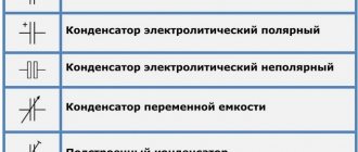
On electrical circuits they are indicated by a pair of short parallel lines perpendicular to the connecting circuit lines. The capacitance value of the element is often placed nearby.
Designation of a capacitor with a constant capacitance
Important! Sometimes in foreign schemes the designation MFD is found. These are not megafarads, but μF.
Possible capacity units:
- micro (μ) means 10 to the -6 power of farad;
- nano (n) – 10 to the -9 degree farad;
- pico (p) – 10 to the -12 degree farad.
The capacitance value is also applied to the surface of the capacitor itself. It is often indicated without unit symbols, especially on small elements. For example, 0.1 is 1 µF = 100 nF.
Sometimes writing units is used instead of a decimal point. If the designation 4n7 appears, this means 4.7 nF.
Capacitor number code
Digital code is often used on small items where printing is difficult:
- the first two numbers are the initial digits of the capacity value;
- the third shows the number of zeros, and the value itself is measured in pF;
- letters may indicate tolerances and voltage ratings.
For example:
- 102 means 1000 pF, not 102 pF;
- 472J is 4700 pF (J indicates 5 percent tolerance).
Important! Non-polar capacitors usually have a capacitance of less than 1 µF.
Video
Coffee capsule Nescafe Dolce Gusto Cappuccino, 3 packs of 16 capsules
1305 ₽ More details
Coffee capsules Nescafe Dolce Gusto Cappuccino, 8 servings (16 capsules)
435 ₽ More details
SIP phones