GOST 2.789-74 ESKD. Symbols are conventional graphic. Heat exchangers
INTERSTATE STANDARD
UNIFIED SYSTEM OF DESIGN DOCUMENTATION
CONDITIONAL GRAPHIC NOTATIONS.
HEAT
EXCHANGER EQUIPMENT GOST 2.78
9- 74
INTERSTATE COUNCIL FOR STANDARDIZATION, METROLOGY AND CERTIFICATION
Minsk
STATE STANDARD OF THE USSR UNION
| Unified system of design documentation CONDITIONAL GRAPHIC NOTATIONS. | GOST 2.789-74 |
By Resolution of the State Committee of Standards of the Council of Ministers of the USSR dated April 29, 1974 No. 1039, the introduction date was established
from 01.01.75
1. This standard establishes conventional graphic designations of heat exchangers in the design documentation of all industries.
2. Conventional graphic symbols of heat exchangers should be constructed from combinations of conventional graphic symbols of housing elements and elements that carry out heat exchange.
Designations of housing elements are in accordance with GOST 2.788-74.
The designations of the elements that carry out heat exchange must correspond to those established in the table. 1.
Examples of constructing conventional graphic symbols for heat exchangers are given in Table. 2.
If there is no need to explain the specific features of elements and devices, they should be depicted using simplified external outlines or general designations based on functional characteristics in accordance with GOST 2.780-96 should be used.
3. Designations of heat exchangers, which have their own graphic symbols, must correspond to those established in table. 3.
4. The dimensions of the designations are not established by the standard. Designations must ensure clarity of the diagram and be drawn in the relationships in which they are made in this standard.
Table 1
| Name | Designation |
| 1. Tubular elements: a) with fixed tube sheets | |
| b) with floating head | |
| c) with a floating head and oil seal | |
| d) with U-shaped pipes | |
| e) with field tubes | |
| e) with U-shaped pipes and separate tube sheets | |
| g) twisted | |
| h) spiral | |
| i) flat | |
| 2. Direct heat transfer elements: a) liquid or gas distributors, heating or cooling | |
| b) centrifugal sprayers | |
| c) nozzle sprayers | According to GOST 2.784-96 |
| d) open flame sprayers | |
| e) radiation heating elements | |
| 3. Warming or cooling shirts | |
| 4. Heat regenerators | |
| 5. Electric heaters | According to GOST 2.745-68 |
table 2
| Name | Designation |
| 1. Shell and tube heat exchangers: a) with fixed tube sheets at pressure in the pipes and inter-tube space above atmospheric | |
| b) with fixed tube sheets at a pressure in the pipes higher and in the inter-tube space lower than atmospheric | |
| c) with a temperature compensator on the casing at pressure in the pipes and inter-pipe space above atmospheric | |
| d) with a floating head at a pressure in the pipes and inter-tube space above atmospheric | |
| e) with U-shaped pipes at pressure in the pipes and inter-pipe space above atmospheric | |
| e) with an oil seal at a pressure in the pipes and interpipe space above atmospheric | |
| g) with a vapor space, with a floating head at a pressure in the pipes and inter-tube space above atmospheric | |
| h) with a steam space, with U-shaped pipes at pressure in the pipes and inter-tube space above atmospheric | |
| i) twisted at pressure in pipes and inter-pipe space equal to atmospheric | |
| 2. Tubular heat exchangers without casing: a) submerged spiral | |
| b) submerged flat | |
| c) irrigation | |
| 3. Heat exchanger with direct heat transfer | |
| 4. Heat exchanger with external heating | |
| 5. Heat exchanger with electric heating | |
| 6. Regenerative heat exchanger | |
| 7. Bias capacitor |
Table 3
| Name | Designation |
| 1. Sheet heat exchangers: a) spiral | |
| b) plate collapsible | |
| c) plate semi-collapsible | |
| d) plate welded block | |
| e) all-welded plate | |
| e) lamellar ribbed | |
| g) lamella | |
| 2. Air-cooled heat exchanger | |
| 3. Heater | |
| 4. Cooling towers | |
| APPENDIX according to GOST 2.793-79. | |
Conditional graphic designations in schemes. Designations for general use (GOST 2.721-74)
This indicates the presence of a protective contact to which grounding is connected.
Switching devices on the diagrams should be shown in the position taken as the initial one, in which the starting contact system is de-energized. If the standard does not contain the required designation, then it is compiled based on the principle of operation of the element, designations adopted for similar types of devices, devices, machines in compliance with the design principles stipulated by the standard.
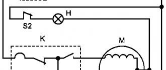
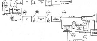
An example of a schematic diagram of a milling machine. If the diagram shows only the power part of the installation, then it is called single-line; if all elements are shown, then it is called complete. I - Branches. It contains a minimum of symbols.
In addition, contacts can perform different functions: contactor, disconnector, switch, etc. E - Electrical connection with the device body.
Using the letter designation, the name of the element is determined, if this is not clear from the drawing, technical parameters, quantity. The symbols reflect only the main function of the contact - closing and opening the circuit. The circuit diagram must clearly identify all the elements included in the installation and shown in the diagram. Letter designations In addition to the fact that the elements on the diagrams have conventional graphic names, they have letter designations, also standardized by GOST
Examples of UGO in functional diagrams
Below is a picture depicting the main components of automation systems.
Examples of symbols for electrical appliances and automation equipment in accordance with GOST 21.404-85
Description of symbols:
- A – Basic (1) and acceptable (2) images of devices that are installed outside the electrical panel or junction box.
- B - The same as point A, except that the elements are located on the remote control or electrical panel.
- C – Display of actuators (AM).
- D – Influence of MI on the regulating body (hereinafter referred to as RO) when the power is turned off:
- RO opening occurs
- Closing RO
- The position of the RO remains unchanged.
- E - IM, on which a manual drive is additionally installed. This symbol may be used for any RO provisions specified in paragraph D.
- F- Accepted mappings of communication lines:
- General.
- There is no connection at the intersection.
- The presence of a connection at the intersection.
UGO in single-line and complete electrical circuits
There are several groups of symbols for these schemes; we present the most common of them. To obtain complete information, you must refer to the regulatory documents; the numbers of state standards will be given for each group.
Power supplies.
To designate them, the symbols shown in the figure below are used.
UGO power supplies on schematic diagrams (GOST 2.742-68 and GOST 2.750.68)
Description of symbols:
- A is a constant voltage source, its polarity is indicated by the symbols “+” and “-”.
- B – electricity icon indicating alternating voltage.
- C is a symbol of alternating and direct voltage, used in cases where the device can be powered from any of these sources.
- D – Display of battery or galvanic power supply.
- E- Symbol of a battery consisting of several batteries.
Communication lines
The basic elements of electrical connectors are presented below.
Designation of communication lines on circuit diagrams (GOST 2.721-74 and GOST 2.751.73)
Description of symbols:
- A – General display adopted for various types of electrical connections.
- B – Current-carrying or grounding bus.
- C – Designation of shielding, can be electrostatic (marked with the symbol “E”) or electromagnetic (“M”).
- D - Grounding symbol.
- E – Electrical connection with the device body.
- F - On complex diagrams, consisting of several components, a broken connection is thus indicated; in such cases, “X” is information about where the line will be continued (as a rule, the element number is indicated).
- G – Intersection with no connection.
- H – Joint at intersection.
- I – Branches.
Designations of electromechanical devices and contact connections
Examples of the designation of magnetic starters, relays, as well as contacts of communication devices can be seen below.
UGO adopted for electromechanical devices and contactors (GOSTs 2.756-76, 2.755-74, 2.755-87)
Description of symbols:
- A – symbol of the coil of an electromechanical device (relay, magnetic starter, etc.).
- B – UGO of the receiving part of the electrothermal protection.
- C – display of the coil of a device with mechanical interlock.
- D – contacts of switching devices:
- Closing.
- Disconnecting.
- Switching.
- E – Symbol for designating manual switches (buttons).
- F – Group switch (switch).
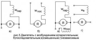
UGO of electric machines
Let us give several examples of displaying electrical machines (hereinafter referred to as EM) in accordance with the current standard.
Designation of electric motors and generators on circuit diagrams (GOST 2.722-68)
Description of symbols:
- A – three-phase EM:
- Asynchronous (squirrel-cage rotor).
- The same as point 1, only in a two-speed version.
- Asynchronous electric motors with phase-phase rotor design.
- Synchronous motors and generators.
- B – Collector, DC powered:
- EM with permanent magnet excitation.
- EM with excitation coil.
Designation of electric motors on diagrams
UGO transformers and chokes
Examples of graphic symbols for these devices can be found in the figure below.
Correct designations of transformers, inductors and chokes (GOST 2.723-78)
Description of symbols:
- A – This graphic symbol can indicate inductors or windings of transformers.
- B – Choke, which has a ferrimagnetic core (magnetic core).
- C – Display of a two-coil transformer.
- D – Device with three coils.
- E - Autotransformer symbol.
- F – Graphic display of CT (current transformer).
Designation of measuring instruments and radio components
A brief overview of the UGO of these electronic components is shown below. For those who want to become more familiar with this information, we recommend viewing GOSTs 2.729 68 and 2.730 73.
Examples of graphic symbols for electronic components and measuring instruments
Description of symbols:
- Electricity meter.
- Picture of an ammeter.
- Device for measuring network voltage.
- Thermal sensor.
- Fixed value resistor.
- Variable resistor.
- Capacitor (general designation).
- Electrolytic capacity.
- Diode designation.
- Light-emitting diode.
- Image of a diode optocoupler.
- UGO transistor (in this case npn).
- Fuse designation.
UGO lighting devices
Let's look at how electric lamps are displayed on a circuit diagram.
An example of how light bulbs are indicated on diagrams (GOST 2.732-68)
Description of symbols:
- A – General image of incandescent lamps (LN).
- B - LN as a signaling device.
- C – Typical designation of gas-discharge lamps.
- D – High-pressure gas-discharge light source (the figure shows an example of a design with two electrodes)
Designation of elements in the electrical wiring diagram
Concluding the topic of graphic symbols, we give examples of displaying sockets and switches.
An example of an image on the wiring diagrams of flush-mounted sockets
How sockets of other types are depicted is easy to find in the regulatory documents that are available on the Internet.
Designation of flush-mounted switches
Designation of sockets and switches
Video on the topic: