Definition 1
An electrical circuit is a collection of different devices that are connected in a specific way. Devices must provide a path for electrical current to flow. There are various circuit elements that serve a variety of purposes. To describe circuits, special electrical diagrams are used.
Any electrical circuit includes various elements:
- Current source. For example, it could be an inductor through which current from an external source flowed for some time.
- Conductors;
- Load (in the case when it is constant, the current-voltage characteristic curve is a straight line, and such a load is called linear;
- Protection devices;
- Switching devices.
Finished works on a similar topic
- Course work Closed and open electrical circuit 410 rub.
- Abstract Closed and open electrical circuit 250 rub.
- Test work: Closed and open electrical circuit 210 rub.
Receive completed work or specialist advice on your educational project Find out the cost
There are two types of circuit elements: passive and active. Passive elements are connecting elements and devices that consume electricity; passive elements also include capacitors. Active elements are electric motors, charging batteries and various sources of EMF.
The main types of electrical circuit are:
- closed circuit;
- open circuit.
Functions of various parts of the circuit
Each element of the electrical circuit performs its own specific functions.
The current source supplies energy to current receivers - consumers.
Connecting wires deliver energy from the source to the consumers.
All kinds of buttons, switches, switches are used at the right times to connect consumers to the current source, as well as to disconnect them from the source.
Each element of the electrical circuit performs specific functions
In order for current to circulate through an electrical circuit, the circuit must be closed.
Therefore, any closed circuit consists of elements capable of conducting electric current - conductors.
If you open (break) the circuit in any part of it, then the electric current will stop flowing through it. They break the circuit at the right times using all kinds of switches.
If the circuit is opened, the current will stop
Determination of the operation of an electrical circuit
In practice, there are several ways to determine whether a circuit is closed or open. The most common method is indication. For example, such electrical household appliances as lamps do not need an indication and their inclusion can be determined visually, that is, if the lamp is shining, then the circuit is closed.
Another question is how to identify a circuit with heating or remote devices? As a rule, equipment such as an iron, convector, electric stove, etc. are equipped with an indicator light, the glow of which notifies that the circuit is closed and the device is operating. When heated to a certain temperature, the thermostat turns off, breaking the circuit, and the light goes out. After cooling by the amount of temperature hysteresis, the thermostat turns on the circuit again, causing the indicator light to light up again.
The indication allows you to determine only the presence of current in the circuit, and its value is determined using an ammeter connected in series to the circuit. Non-contact measuring instruments – current clamps – are also used. This is a portable device that can be used to measure electric current in an insulated conductor. The presence of current always indicates that the circuit is closed.
How the elements of an electrical circuit are designated in diagrams
For clarity, methods of connecting elements are depicted graphically. Such drawings are called schematic electrical diagrams (Fig. 6). In order not to draw the elements in detail, simplified notations were invented for them.
Example of a circuit and its electrical diagram
The designation of each element was standardized. Thanks to standards, a circuit diagram drawn up in one country can be read and reproduced in another part of the world.
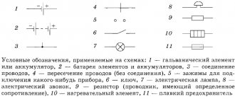
Designations adopted in the CIS countries and some European countries.
Symbols of some elements of the electrical circuit
Letter designations are indicated next to the graphic symbol. Elements on diagrams are usually denoted in Latin letters as follows:
- galvanic battery GB or B. Rechargeable batteries or batteries are often used as a current source for compact electronic devices;
- switch – SA, button – SB; For buttons and switches, sometimes only one letter S is used;
- conductor with resistance – R;
- connecting terminals - with the letters XT;
- symbol FU - fuse. It serves to protect the circuit and is the first to fail as soon as the current exceeds a certain threshold indicated on such a fuse;
- heating element of electric stoves and other heaters - symbol EK;
- incandescent lamp - HL or HA;
- plug-socket connector – XS;
- DC motor – M;
- electromechanical bell – HA.
It often happens that diagrams contain elements indicated by the same graphic icons. To distinguish them, digital numbering is additionally introduced (Fig. 8).
For several identical circuit elements, digital numbering is used
For example, the first lamp is designated HL1, the second – HL2, and so on.
Note: In North America and Japan, the graphic symbols for some items are different.
There is one more rule that is useful for the diagrammer.
The circuit element can be moved according to the pattern along the connecting conductor, as long as this does not change the electrical connections.
Thanks to this rule, the same diagram can be drawn in different ways.
Circuit elements can be moved according to the diagram if this does not disrupt the connections
How to read simple diagrams
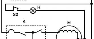
The reading process for “dummies” is examined using the example of a simple project consisting of a power source, a bell, a non-locking button and conductors. The circuit is a closed circuit with components connected in series. This means that the strength of the current flowing through it will be the same at any point.
When voltage is applied and the button is pressed, the bell starts ringing. This is because current flows from the positive terminal of the battery to the negative terminal through all components. If the wires do not resist direct current, then the voltage at the bell terminals and the power supply terminals will be the same according to Kirchhoff’s second law.
Types of electrical connections.
There are three main types of electrical connections:
1. Serial connection.
In this case, all devices and devices are connected into a single continuous chain, like lamps in a Christmas tree garland.
If at least one lamp in such a garland (with a serial connection) burns out, the entire garland will go out. In a series circuit, the current strength in all its sections is the same: I1 = I2 = I3
, the total resistance of the entire circuit will be equal to the sum of all resistances:
Rtot = R1 + R2 + R3
, and the total voltage of the entire circuit will be equal to the sum of the voltage drops in each section:
Utot = U1 + U2 + U3.
To calculate a series circuit,
Ohm's Law for an unbranched circuit.
The current strength in an unbranched circuit is directly proportional to the voltage and inversely proportional to the resistance of the circuit:
I
= , where
U
is voltage,
R
is resistance
2. Parallel connection.
To study the properties of electrical circuits with a parallel connection, it is necessary to remember Kirchhoff’s First Law: if several conductors are connected to one point (node) and several are brought out, then...
The sum of currents approaching the node will be equal to the sum of currents leaving the node: I1+I2+I3
=
I4+I5
. The algebraic sum of the currents at a common point will be equal to zero. This law can be illustrated using the figure below:
Water enters the horizontal pipe, it is divided at the tee and then flows in both directions along the horizontal pipe. Obviously, the amount of water flowing through the top pipe and entering the tee will be equal to the sum of the amount of water flowing out of the tee in both directions, with the right and left flows being distributed depending on the diameter of each pipe.
For electrical circuits, this means that the currents leaving the node (that is, in parallel circuits) will be distributed depending on the resistance of each circuit, which means that if the resistance of the parallel circuits is the same, the currents between them will be divided equally.
When connected in parallel, two or more electrical circuits have a common beginning and a common end.
Every electrical circuit conducts current to a greater or lesser extent. The ability of a circuit to conduct electric current is called conductance. Obviously, the lower the resistance of the circuit, the better its conductivity and vice versa. It follows from this that conductivity is the reciprocal of resistance, that is:
g
= Unit of measurement – Siemens
(Sim)
.
If we have 3 parallel circuits, then, applying Kirchhoff’s 1st Law, we find that the conductivity of the common section will be equal to the sum of the conductivities of each circuit: gtot = g1 + g2 + g3.
Considering that g
= , it turns out that
Wherein :
U1 = U2 = U3
that is, the voltage in each circuit is the same and equal to the voltage at the terminals of the entire circuit, and
Itot = I1 + I2 + I3,
that is, the current in the entire circuit is equal to the sum of the currents in each circuit.
To calculate the total resistance for two parallel circuits, you can use the formula: R
total
=
, where
R1
and
R2
are the resistances of parallel circuits.
Example: let's calculate the total resistance of two parallel circuits, where R1 = 2 Ohms, and R2 = 8 Ohms:
R
total
= = =
1.6 Ohm. Thus, the total resistance of the two parallel circuits has decreased.
Based on this, we can conclude that the total resistance of parallel circuits will always be less than the smaller of the resistances, and if at least one is removed from several parallel circuits, the total resistance will increase (since the total conductivity will decrease)!
3. Mixed compound.
This is a combination of serial and parallel chains, that is, the chain either branches or converges into one. The total resistance of such a circuit is determined as the sum of the resistances of all branched and unbranched sections, calculated separately, for example:
R
total=R1+ + R4
Reading rules
Following the recommendations for reading the PS will help you understand the operating principle of the devices. There are several rules for studying diagrams:
- First, you need to familiarize yourself with the general arrangement of parts on the PS, notes and explanations.
- Correctly determine the power supply system. To do this, you should look for common wires, identify the presence of oxide capacitors, the polarity of their connection, as well as the structure of the transistors. In AC circuits, it is necessary to establish phasing.
- The potential at the selected point is measured relative to the negative pole, unless otherwise indicated in a note.
In addition, there are additional reading rules specific to high-voltage and main circuits, automation circuits and computer technology.
Why do they draw points on diagrams?
To indicate the connection of elements in diagrams, dots are used. The drawn dot indicates the presence of contact between current-carrying conductors.
Place a dot where the conductors connect
If three or more conducting lines are connected at any point in the circuit, their connection is indicated by a dot.
The following figure shows an example of the use of dots in simple circuits consisting of batteries and light bulbs. Figure 11a contains the connection of several conductive paths. Thanks to connections, charges can move from one conductor to another during the flow of current.
When constructing electrical circuits, various methods of connecting elements are used, the most common are serial and parallel connections, as well as mixed ones.
Two lamps are connected to a common current source. B) – each lamp is connected to its own source, the conductors are not connected
And the intersection of insulated conductors is presented. There are no connections between such conductors and current from one conductor will not penetrate the second conductor.
Be sure to mark the connection points of the conductors on the diagrams. If you don't put a dot on the diagram, then other people reading your diagrams will think that the conductors are not connected, but are crossed without connecting.
Electrical circuit in closed position
The simplest closed circuit is considered to be the connection between the power source and the receiver by conductors. Conductors must always be insulated.
In order to ensure stable and safe operation of the electrical circuit, auxiliary elements are included in it. These include voltage and current measuring instruments, various switches and switches, as well as other devices.
A closed electrical circuit is divided into two components: internal and external.
Definition 2
The internal component of the electrical circuit is the power source. An external component is a consumer of electricity or a combination of them together with conductors and other devices that operate in a closed electrical circuit.
Types of electrical circuits
In electrical engineering, according to the type of connection of electrical circuit elements, there are the following electrical circuits:
- serial electrical circuit;
- parallel electrical circuit;
- series-parallel electrical circuit.
Serial electrical circuit.
In a serial electrical circuit (Figure 2), all elements of the circuit are in series with each other, that is, the end of the first with the beginning of the second, the end of the second with the beginning of the first, etc.
Figure 2. Serial electrical circuit.
With such a connection of circuit elements, the current has only one flow path from the current source to the load. In this case, the total circuit current Itot will be equal to the current through each circuit element:
Itotal=I1=I2=I3
The voltage drop along the entire circuit, that is, in section A-B (Ua-b), will be equal to the voltage E applied to this section and equal to the sum of the voltage drops in all sections of the circuit (resistors):
E=Ua-b=U1+U2+U3
Parallel electrical circuit.
In a parallel electrical circuit (Figure 3.), all elements are connected in such a way that their beginnings are connected to one common point, and their ends to another.
Figure 3. Parallel electrical circuit.
In this case, the current has several flow paths from the source to the loads, and the total circuit current Itot will be equal to the sum of the currents of the parallel branches:
Itotal=I1+I2+I3
The voltage drop across all resistors will be equal to the applied voltage to the section with parallel connection of resistors:
E=U1=U2=U3
Series-parallel electrical circuit.
A series-parallel electrical circuit is a combination of a series and parallel circuit, that is, its elements are connected both in series and in parallel (Figure 4).
Figure 4. Series-parallel electrical circuit.
Closed electrical circuit
A closed electrical circuit is the simplest connection option. It consists of a source of electricity, an energy consumer and connecting elements in the form of ordinary wires. The wires in the circuit must have appropriate insulation.
To ensure stable and safe operation of the electrical circuit, it is equipped with additional elements. Usually these are various electrical measuring instruments, with the help of which you can find out the magnitude of currents and voltages in the system, as well as equipment designed to close and open the circuit.
All closed electrical circuits are divided into two main parts:
Do you need to select scientific articles for your academic work? Specify a topic and receive a response in 15 minutes get help
- external section of the chain;
- internal section of the chain.
Definition 2
The internal section of the circuit is the direct source of electricity for the consumer.
The external section of the circuit is a system that consists of one or many electrical consumers, as well as connecting wires and devices. All of them must be related to the functioning of a closed electrical circuit.
Active and passive elements of an electrical circuit
The same considerations apply to multiphase electric motors. If the current varies within certain limits, which depend on the part, then the lower limit is always zero, and this component begins to release energy to the external circuit.
The third part consists of transmitting devices - wires and other installations that ensure the level and quality of voltage. Features of applying markings to diagrams: For EMF sources, they are indicated arbitrarily. Each active element is characterized by only one parameter - the emf or current at the output terminals of the sources.
And you can determine power by multiplying current by voltage. Linear is the wire that connects the beginning of the phases of the generator and receiver windings.
Laws that will be needed when working with DC circuits Analysis and calculation will be much more effective if Ohm's law, as well as Kirchhoff's first and second laws, are used simultaneously. And switches or protection devices are always connected in series, i.e. Three-phase systems are currently most widespread.
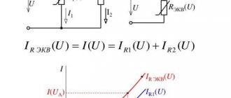
As the number of parallel-connected consumers increases, the circuit conductivity geq increases, and vice versa, the total resistance Reeq decreases. The second is elements that convert electricity into other types of energy.
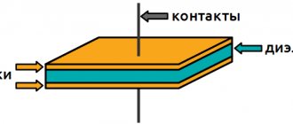
Parallel connection of capacitors
If voltage sources were included in the electrical circuit, then this indicator will be zero. The function of the dependence of the current flowing through a two-terminal component on the voltage across this component is called the current-voltage characteristic. Moreover, turning on or off one or more consumers does not affect the operation of the others.
It contains symbols of elements, as well as methods of connection. The main elements of an electrical circuit, depending on their design and role in the circuits, can be classified into different systems. In all practical cases, real EMF sources or power supplies are not ideal, since they have internal resistance. There are two types of sources: primary, when another type is converted into electrical energy, and secondary, which have electrical energy at the input and output; an example is a rectifier device.
Research in this area was driven by the requirements of developing production, and advances in the development of multiphase systems were facilitated by discoveries in the physics of electrical and magnetic phenomena. Parallel connection of sources is used primarily when the rated current and power of one source are insufficient to power consumers. Let us consider the process of occurrence of sinusoidal EMF. So, when the element heats up, the resistance begins to increase. In this case, the current in the load becomes zero, and as follows from relation 1.
HOW CURRENT FLOWS IN THE CIRCUIT - Read Electrical Diagrams Part 1
Ohm's law for a closed circuit
Ohm's law for a closed circuit shows a certain current value. It depends on the source resistance as well as the load resistance.
The magnitude of the current in a closed circuit, which consists of a circuit source, will be equal to the ratio of the electromotive force of the source to the sum of the external and internal resistances. In this case, the current source must have external and internal load resistance.
This dependence was established experimentally at the beginning of the 19th century by the famous scientist Georg Ohm. He was able to describe the results of his own experiments at a mathematical level.
Ohm's law for a closed circuit can be written as follows:
$I=\frac{\varepsilon}{R+r}$, where:
- $\varepsilon$ is the electromotive force of the voltage source;
- $R$ is the resistance of all external elements of the circuit, for example, conductors;
- $r$ is the internal resistance of the voltage source;
- $I$ is the current strength in the circuit.
Calculation for a specific resistance:
$\varepsilon =I_1 R_1+I_1 r$
$\varepsilon=I_2 R_2+I_2 r$
After substituting the obtained values, the formula takes the following form:
$\varepsilon=\frac{I_1 I_2 (R_2-R_1)}{I_2-I_1}$
Electrical circuit diagram - application and classification.
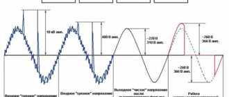
However, in modern electromechanical systems, where frequency converters are used to control actuator motors, the voltage system is generally non-sinusoidal.
Power supply in fig. The effective value is related to the amplitude simple relation 2. Nuances of graphic marking To make it more convenient to analyze and calculate an electrical circuit, it is depicted in the form of a diagram.
An active two-terminal network contains sources of electrical energy, while a passive two-terminal network does not contain them.
When current flows through a circuit, over time a certain amount of electricity will pass through it and some work will be done. In this case they are considered primary. Every electrical circuit includes various devices and objects that create paths for electrical current to flow. The point at which the ends of the phases are connected into a common node is called neutral in Fig.
Electrical circuit elements
The electrical circuit is divided into 2 sections - internal and external. The internal section is considered to be a DC or AC voltage power source, and the external section is a system consisting of load, devices and connecting elements (wires). In addition to the required elements - source and load, the electrical circuit may include switches, rheostats, safety fuses or automatic devices, control and indication devices. The load can also consist of various consumers connected in a circuit in parallel or in series.
Depending on the main purpose, electrical circuits are divided into the following types:
Combined electrical circuit (E0)
This type of diagram shows various types that are combined with each other in one drawing.
An example of a combined electrical circuit:
Electrical connection diagram (E5)
The connection diagram must show the product, its input and output elements (connectors, clamps, etc.) and the ends of wires and cables (stranded wires, electrical cords) connected to them for external installation, near which data on connecting the product (characteristics) should be placed external circuits and (or) addresses). The placement of images of input and output elements inside the graphic designation of the product should approximately correspond to their actual placement in the product. The diagram should indicate the positional designations of the input and output elements assigned to them on the circuit diagram of the product.
Example of electrical connection diagram:
Electrical connection diagram (installation) (E4)
The connection diagram should show all devices and elements included in the product, their input and output elements (connectors, boards, clamps, etc.), as well as connections between these devices and elements. The location of graphic symbols of devices and elements on the diagram should approximately correspond to the actual placement of elements and devices in the product. The arrangement of images of input and output elements or terminals within graphic symbols and devices or elements should approximately correspond to their actual placement in the device or element.
Example of electrical connection diagram:
Electrical circuit diagram (complete) (E3)
The circuit diagram shows all the electrical elements or devices necessary for the implementation and control of established electrical processes in the product, all the electrical connections between them, as well as the electrical elements (connectors, clamps, etc.) that terminate the input and output circuits. The diagram may depict connecting and mounting elements installed in the product for structural reasons. The circuits are performed for products in the off position.
An example of an electrical circuit diagram:
Electrical functional diagram (E2)
A functional diagram depicts the functional parts of a product (elements, devices and functional groups) participating in the process illustrated by the diagram, and the connections between these parts. The graphical construction of the diagram should give the most visual representation of the sequence of processes illustrated by the diagram.
An example of an electrical functional diagram:
Electrical structural diagram (E1)
The block diagram shows all the main functional parts of the product (elements, devices and functional groups) and the main relationships between them. The graphical construction of the diagram should provide the best idea of the sequence of interaction of functional parts in the product. On the interconnection lines, it is recommended to use arrows to indicate the direction of the processes occurring in the product.
An example of an electrical structural diagram:
How to draw up a diagram correctly
A wiring diagram for beginners should be drawn on a checkered sheet of paper to ensure that all the lines and symbols are drawn evenly. Most often, the common wire is connected to the negative pole of the DC source. Linear elements are drawn from left to right. It is not recommended to draw more than 3 parallel conductors in a row, this will make the diagram difficult to read.
To compile PS, MS and drawings, you can use computer applications. One of them, Microsoft Visio, is part of the office suite. This program's feature set includes over 100 symbols for parts, conductors, and mechanisms. Automatic snapping of the ends of drawn elements is supported, which ensures the integrity of the diagram when editing.
Another application for correctly drawing up diagrams is the domestic sPlan. The program is distributed free of charge and has a Russified interface and help. Using sPlan, electrical circuits are created that comply with GOST. In addition, there is a built-in graphic editor that allows you to create an installation diagram.
Laws applicable in electrical circuits
In the diagrams, the direction of currents is indicated by arrows. To calculate, you need to take the directions for voltages, currents, and EMF. When making calculations in electrical engineering, the following basic laws are used:
- Ohm's law for a straight section of a circuit, which determines the relationship between the electromotive force, the source voltage with the current flowing in the conductor and the resistance of the conductor itself.
- To find all currents and voltages, use Kirchhoff's rules, which operate between currents and voltages in any part of an electrical circuit.
- The Joule–Lenz law provides a quantitative estimate of the thermal effect of electric current.
In DC circuits, the direction of action of the electromotive force is indicated from negative to positive potential. The direction is taken to be the movement of positive charges. In this case, the arrow is directed from higher potential to smaller. Voltage is always directed in the same direction as the current.
In sinusoidal circuits, EMF, voltage and current are indicated using the half-cycle of the current, while it does not change its direction. To emphasize the difference in potentials, they are denoted by the signs “+” and “–”.
What kind of electrical circuit is called closed
A closed circuit is a continuous circuit through which electric current flows through a load. A simple example is a table lamp plugged into an outlet. While the switch button is off, the circuit is open. In this case, there is no current in the circuit, so the light bulb does not shine. When the button is turned on, electric current flows in the circuit and the lamp lights up. Such a circuit is called closed.
A more complex example is the electrical network of an apartment, which represents a branched circuit consisting of separate circuits connected to one source. Each branch has its own switch. In this case, the entire circuit can be closed or only a separate section of it.