Color designation in electrical installations of buses, wires, conductors
Tire color code
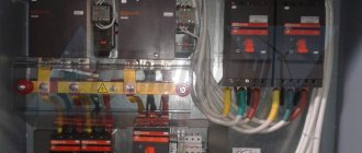
According to the sixth edition of the PUE, electrical installations must be able to easily recognize parts related to their individual elements (simplicity and clarity of diagrams, proper arrangement of electrical equipment, inscriptions, markings, colors).
The alphanumeric and color designations of tires of the same name in each electrical installation must be the same.
Tires must be marked:
1) with alternating three-phase current:
- A buses - yellow,
- B buses - green,
- C buses - red,
- zero working N - blue,
- the same tire, used as a zero safety tire, with longitudinal stripes of yellow and green colors;
2) with alternating single-phase current:
- bus A , connected to the beginning of the power source winding, is yellow,
- bus B attached to the end of the winding is red.
3) at constant current:
- positive bus [ + ] - red,
- negative [ − ] - blue,
- zero working M - blue;
4) redundant as a redundant main bus; if the reserve tire can replace any of the main tires, then it is indicated by transverse stripes in the color of the main tires.
• Single-phase busbars , if they are a branch from the busbars of a three-phase system, are designated as the corresponding three-phase current busbars.
The color coding must be carried out along the entire length of the tires if it is also provided for more intensive cooling or for anti-corrosion protection.
It is allowed to carry out a color designation not along the entire length of the busbars, only a color or only an alphanumeric designation, or a color in combination with an alphanumeric designation only at the points where the busbars are connected; if non-insulated busbars are not available for inspection during the period when they are energized, then it is permissible not to mark them. At the same time, the level of safety and visibility when servicing the electrical installation should not be reduced.
For color and digital designation of individual insulated or non-insulated conductors, colors and numbers must be used in accordance with GOST R 50462 * “Identification of conductors by colors or digital designations”.
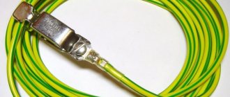
Protective grounding conductors in all electrical installations, as well as neutral protective conductors in electrical installations with voltages up to 1 kV with a solidly grounded neutral, including busbars, must have the letter designation PE and color designation in alternating longitudinal or transverse stripes of the same width (for busbars from 15 to 100 mm) yellow and green.
Zero working (neutral) conductors are designated by the letter N and the color blue. Combined neutral protective and neutral working conductors must have the letter designation PEN and a color designation: blue along the entire length and yellow-green stripes at the ends.
The alphanumeric and color designations of tires of the same name in each electrical installation must be the same.
Tires must be marked:
- 1) with alternating three-phase current: buses of phase A - yellow, phase B - green, phase C - red;
- 2) with single-phase alternating current, bus B, connected to the end of the power source winding, is in red, bus A, connected to the beginning of the power source winding, is yellow. Single-phase current buses, if they are a branch from the buses of a three-phase system, are designated as the corresponding three-phase current buses;
- 3) at constant current: positive bus ( + ) - in red, negative ( − ) - in blue and zero operating M - in blue.
———-
* Note: GOST R 50462 has been replaced by GOST R 50462-2009.
Wiring designation
According to PUE-7, electrical wiring must be able to be easily identified along the entire length of the conductors by color:
- blue color - to indicate the zero working or middle conductor of the electrical network;
- two-color combination of green and yellow - to indicate the protective or neutral protective conductor;
- a two-color combination of green and yellow along the entire length with blue marks at the ends of the line, which are applied during installation - to indicate the combined neutral working and neutral protective conductor;
black, brown, red, purple, gray, pink, white, orange, turquoise - to indicate the phase conductor.
Color designation according to functional purpose
Color identification of conductors according to the functional purpose of the circuits in which they are used (according to GOST 12.2.007.0):
- for conductors in power circuits - black;
- for conductors in control, measurement and signaling circuits of alternating current - red;
- for conductors in DC control, measurement and signaling circuits - blue;
- for neutral protective conductors - a combination of green and yellow;
- for conductors connected to the neutral working conductor and not intended for grounding - blue.
Wire Identification
According to GOST IEC 60204-1-2002 “ELECTRICAL EQUIPMENT OF MACHINES AND MECHANISMS”, if color marking is used to identify wires, the following colors can be used: black, brown, red, orange, yellow, green, blue (including light blue), violet, grey, white, pink, turquoise[1].
For safety reasons, the colors green and yellow should not be used if they could be confused with the green-yellow two-color combination.
The protective conductor must be easily recognizable due to its shape, location, marking or color. When color designation is used, it should be a two-color combination of green and yellow. It is used along the entire length of the wire. This combination is intended for protective conductor only.
On insulated wires, the two-color combination of green and yellow must be such that over a length of 15 mm one of the colors covers at least 30%, but not more than 70% of the surface of the wire, and the other color covers the remaining part.
When protective conductor is easily identifiable due to its shape, design, location (e.g., braided conductor), or when insulated conductor is not easily accessible, color coding along its entire length is not necessary. However, the ends or accessible parts shall be clearly marked with the graphic symbol 417-IEC-5019 [2] or a two-color combination of green and yellow.
When the circuit includes a neutral conductor, indicated by color, the latter shall be light blue (IEC 60446, 3.1.2). Where possible, light blue should not be used to indicate other wires. In the absence of a neutral wire, the light blue wire can be used for other purposes, but not as a protective wire.
When color designation is used, bare wires used as neutral wires should be marked with a light blue stripe 15 to 100 mm wide, a color that is duplicated on each sheath, equipment or in each accessible location, or painted light blue along the entire length .
Identification of other wires should be carried out using color (either as a whole, or in one or more stripes), numbers, letters, or a combination of these. The numbers must be Arabic, the letters must be Latin (uppercase or lowercase).
• Insulated unipolar rigid wires must have the following color designation:
- black - AC and DC power circuits;
- red - AC control circuits;
- blue - DC control circuits;
- orange - interlock control circuits powered by an external energy source.
Exceptions to the above are permitted:
- for internal cables on independent devices, purchased separately with a complete set of cables;
- when the insulating material used cannot be painted in the required colors;
- when multi-wire cable is used, except for the green-yellow two-color combination.
| [1] Note: The list of colors is taken from IEC 60757. |
| [2] |
| Graphic symbol 417-IEC-5019 |
https://www.electromonter.info
Wire colors in a single-phase network
Different colors of wire insulation become most relevant when the installation of electrical wiring is carried out by one person, and repairs and maintenance are carried out by another. The main purpose of color marking is to make it easy and quick to determine the purpose of any of the wires.
Phase wire colors
According to the PUE, phase wires in a single-phase electrical network can have the following insulation color - black, red, brown, gray, purple, pink, orange, white, turquoise. This color marking is quite convenient - when you see a wire with this color of insulation, it becomes clear that you have a phase in front of you (but it is still better to double-check, since in practice there are cases when the marking is not observed).
Zero working conductor or neutral
The neutral or neutral working conductor (N) is usually made with a wire with blue insulation.
Neutral protective conductor and neutral combined conductor
The neutral protective conductor (PE) has a yellow-green insulation color. The combined neutral and working conductor (PEN) has a blue color with yellow-green marks at the end, or vice versa - a yellow-green color with blue marks at the end.
If you do not have a wire of a suitable color, then installation can be done with a wire of any color (except for the protective PE conductor that is colored) by marking the ends of this wire with colored electrical tape or heat-shrink tubing, which have a color indicating the purpose of the conductor. You can also mark the ends of the conductor with the desired color in the case when the installation has already been carried out with a conductor of a different color.
Below are the colors that indicate phase, neutral, protective and combined conductors:
What letter and color designations should buses have for direct current?
| Positive bus (+) - in red, negative (-) - in blue and zero working M - in blue | Correct answer |
| Positive bus (+) - green, negative (-) - red and zero working M - blue | Incorrect answer |
| Positive bus (+) - in red, negative (-) - in blue and zero working M - in white | Incorrect answer |
| Positive bus (+) - green, negative (-) - blue and zero working M - blue | Incorrect answer |
What safety requirements do the PUE impose on fencing and closing devices?
| Must be designed so that they can only be removed or opened using keys or tools | Correct answer |
| They must have free access | Incorrect answer |
| The rules do not provide for special requirements | Incorrect answer |
What rooms are classified as electrical rooms?
| Premises containing electrical equipment with voltages above 220 V | Incorrect answer |
| Rooms or areas fenced off (for example, by nets) in which electrical equipment is located, accessible only to qualified service personnel | Correct answer |
| Any premises with electrical equipment with a power above 10 kW | Incorrect answer |
| Premises containing any electrical installations | Incorrect answer |
How often is electrical safety knowledge testing carried out for electrical personnel?
| At least once a year | Correct answer |
| At least once every six months | Incorrect answer |
| At least once every three years | Incorrect answer |
| At least once every five years | Incorrect answer |
Who should keep the keys to electrical installations?
| Registered with operational staff | Correct answer |
| Registered with repair personnel | Incorrect answer |
| Registered with the chief power engineer's service | Incorrect answer |
| Registered with the security service of the premises in which the electrical installation is located | Incorrect answer |
Which of the listed works can be classified as work performed as part of routine operation in electrical installations with voltages up to 1000 V?
| Removal and installation of electricity meters, other instruments and measuring instruments | Correct answer |
| Repair of starting and switching equipment installed on panels | Incorrect answer |
| Replacing lamps and cleaning luminaires at a height of more than 2.5 m | Incorrect answer |
| Any of the listed works | Incorrect answer |
What material should artificial grounding conductors be made of?
| Made from black or galvanized steel or copper | Correct answer |
| Made of copper and aluminum | Incorrect answer |
| Made from steel, copper and aluminum | Incorrect answer |
| Made from galvanized steel and aluminum | Incorrect answer |
How are dielectric gloves checked for punctures?
| By twisting them towards the fingers | Correct answer |
| By stretching and visual inspection | Incorrect answer |
| By immersing in water and checking that no air bubbles appear | Incorrect answer |
| By electrical testing | Incorrect answer |
What background should the warning sign “Caution! Electric voltage”, which is applied using a stencil to a reinforced concrete overhead line support?
| White | Incorrect answer |
| Yellow | Incorrect answer |
| The background is the color of the concrete surface | Correct answer |
How should you move in the “stepping” voltage zone?
| Just like on ordinary land | Incorrect answer |
| "Goose step" | Correct answer |
| Big steps very quickly | Incorrect answer |
| It doesn't matter which way you go | Incorrect answer |
How are zero working (neutral) conductors designated?
| Indicated by the letter N and green | Incorrect answer |
| Indicated by the letter N and white | Incorrect answer |
| Indicated by the letter N and blue color | Correct answer |
| Indicated by the letter N and the color yellow | Incorrect answer |
What letter and color designation should protective grounding conductors in electrical installations have?
| Must have the letter PEN and a blue color along the entire length | Incorrect answer |
| Must have the letter designation PE and color designation with alternating longitudinal or transverse stripes of the same width (for tires from 15 to 100 mm) of yellow and green colors | Correct answer |
| Must have the letter PEN and color designation: blue along the entire length and yellow-green stripes at the ends | Incorrect answer |
| Indicated by the letter N and blue color | Incorrect answer |
What should an employee do if he notices a malfunction in the electrical installation or protective equipment?
| Take corrective action | Incorrect answer |
| Immediately report this to your immediate supervisor, or, in his absence, to your superior manager. | Correct answer |
| Call a repair service | Incorrect answer |
| Troubleshoot yourself | Incorrect answer |
When is an extraordinary personnel knowledge test carried out?
| When new or revised rules and regulations come into effect for the Consumer | Incorrect answer |
| At the request of government supervisory and control authorities | Incorrect answer |
| When testing knowledge after receiving an unsatisfactory grade | Incorrect answer |
| If there is a break in work in this position for more than 6 months | Incorrect answer |
| In any of the above cases | Correct answer |
Which electrical safety group should employees from among the operational personnel who solely service electrical installations have?
| Not lower than group II | Incorrect answer |
| Not lower than group III | Correct answer |
| II or III group | Incorrect answer |
| IV group | Incorrect answer |
How are tires designated for single-phase alternating current?
Answers from Rostechnadzor on electrical safety (ES) for electrical personnel of organizations operating consumer electrical installations on certification questions for test tasks. Questions with correct answers are confirmed by an excerpt from the regulatory documentation on which the Olympox tests were compiled.
How are tires designated for single-phase alternating current?
• Bus B, connected to the end of the power source winding, is in red, bus A, connected to the beginning of the power source winding, is yellow.
• Bus B, connected to the end of the power source winding, is in green, bus A, connected to the beginning of the power source winding, is yellow.
• Bus A, connected to the end of the power source winding, is in blue, bus B, connected to the beginning of the power source winding, is green.
• Bus B, connected to the end of the power source winding, is in blue, bus A, connected to the beginning of the power source winding, is green.
Excerpt from regulatory documentation:
Rules for electrical installations-1
1.1.30. The alphanumeric and color designations of tires of the same name in each electrical installation must be the same. Tires must be marked:
1) with alternating three-phase current: buses of phase A - yellow, phase B - green, phase C - red;
2) with single-phase alternating current, bus B, connected to the end of the power source winding, is in red, bus A, connected to the beginning of the power source winding, is yellow.
Single-phase current buses, if they are a branch from the buses of a three-phase system, are designated as the corresponding three-phase current buses;
3) at constant current: positive bus (+) - in red, negative (-) - in blue and zero operating M - in blue. The color coding must be carried out along the entire length of the tires if it is also provided for more intensive cooling or anti-corrosion protection.
Standard color coding of wires and busbars
Colored insulation of conductors today is an essential attribute for successful and correct installation of electrical wiring. This solution is by no means a way to make wires beautiful and attractive to the consumer; it is a convenient color marking, standardized and regulated throughout the civilized world, which is, without exaggeration, a necessity.
Color-coded wires provide precise identification of each conductor. The color of the core insulation determines its purpose in a group of several conductors and facilitates the switching and installation process.
This solution eliminates possible errors that could lead to fatal electric shock or short circuit. Electrical repairs and maintenance are also safer when wires are accurately marked.
The standard set out in the PUE strictly defines the colors of the markings, and thanks to this standard it becomes possible to easily identify each conductor, each cable core in a group by color or alphanumeric code.
As a rule, the entire conductor has a certain color, but it is also permissible to mark only the ends of individual cores at switching points where it is possible to use colored electrical tape or colored cambrics. Next, we will look in more detail at how exactly such marking is carried out for single-phase, three-phase and direct current networks.
For three-phase AC networks
In three-phase alternating current networks, high-voltage transformer inputs both at stations and substations, as well as busbars, are painted in the following colors, according to the phases:
- Phase “A” is colored yellow;
- Phase “B” is colored green;
- Phase “C” is colored red.
For DC networks
DC circuits are characterized by only two buses: positive and negative. Here the positive wire (positive charge bus) is marked in red, and the negative wire (negative charge bus) is marked in blue, because the neutral and phase wires are fundamentally absent here. The middle wire (M) is marked blue.
In the case where a dc network containing two conductors is created by branching from a three-wire dc circuit, the conductors are marked in the same way as the corresponding conductors of the original three-wire circuit.
Phase, neutral and ground in electrical wiring
AC electrical networks are now always laid with multi-core wires insulated with cores of different colors, this greatly simplifies the installation process. If the wiring in the room is carried out by one installer, and in the future other people will carry out maintenance and repair of the network, they will no longer be forced to constantly identify “phase” and “zero”, they will simply be guided by color.
But in the old days this was a real problem, because the insulation was one color - either white or black. Now a standard has been developed, and in accordance with GOST R 50462 “Identification of conductors by colors or digital designations”, the cores are separate and in cables have strictly regulated designations.
The function of marking is to create the ability to quickly and easily visually determine the purpose of each specific conductor for any section of it; this is one of the main requirements of the PUE. What colors, according to GOST, should conductors have in AC electrical installations for voltages up to 1000 volts and with a solidly grounded neutral, which includes almost all residential buildings and administrative buildings?
