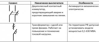
Designation of difavtomats on a single-line diagram
For a residual current circuit breaker (RCBO or difavtomat) there is no individual graphic and letter designation approved in GOST or SP.
Even in the modern GOST R IEC 60617-DB-12M-2015, which contains all conventional graphic signs for electrical circuits, which came into force in 2021, RCBOs are not presented.
Therefore, the designation of a difavtomat on electrical diagrams is formed in accordance with GOST 2.702-2011 “Unified System of Design Documentation (ESKD), which allows you to create schematic symbols of equipment or devices yourself, if they are not defined in other regulations, standards and rules.
According to it, the difavtomat on a single-line diagram is shown as follows:
note
Like the differential machine itself, its schematic view is formed by merging the designations AB (circuit breaker) and RCD, combining their graphic features.
Since state standards do not regulate the type of difavtomat, on all plans, a block with conventional graphic symbols (UGO) is necessarily added , in which a decoding and explanation of the symbols used is given.
Letter designation
The correct letter marking of the difavtomat on the diagrams is QF , only it fully complies with GOST 2.710-81 ESKD. At the same time, such a letter designation does not provide an accurate definition of the functions of the device and does not reveal the principle of operation.
Moreover, according to the same standard, both AV and residual current devices (RCDs) are marked. This often misleads electricians or electricians, so designers in electrical projects often independently enter markings: Q, QD, QFD, QDF, etc.
Difference between RCD and DIFAVTOMATA in the diagrams
Due to the external similarity of the difavtomat and the RCD on single-line diagrams, many confuse them, although, with a direct comparison, clear differences are visible:
The residual current circuit breaker, unlike the RCD, has additional graphic signs inherent in modular circuit breakers, these are automatic operation and the function of the circuit breaker (marked in the image above).
The function of the switch is often not shown by electrical circuit designers at all, they leave only a sign of automatic operation, therefore, it is better to always focus on it and then you will definitely not confuse these devices.
Source: https://RozetkaOnline.ru/poleznie-stati-o-rozetkah-i-vikluchateliah/item/205-oboznachenie-difavtomatov-na-odnolinejnoj-skhema
Designation of the difavtomat on the diagram
No person, no matter how talented and savvy he may be, can learn to understand electrical drawings without first becoming familiar with the symbols that are used in electrical installation at almost every step. Experienced specialists claim that only an electrician who has thoroughly studied and mastered all the generally accepted designations used in project documentation can have a chance to become a true professional in their field.
Greetings to all friends on the website “Electrician in the House”. Today I would like to pay attention to one of the initial issues that all electricians face before installation - this is the design documentation of the facility.
Some compose it themselves, while others are provided by the customer. Among the multitude of this documentation, you can find copies in which there are differences between the symbols of certain elements. For example, in different projects the same switching device can be graphically displayed differently. Has this ever happened?
It is clear that it is impossible to discuss the designation of all elements within one article, so the topic of this lesson will be narrowed, and today we will discuss and consider how the designation of ouzo is carried out on the diagram .
Every novice master must carefully familiarize himself with generally accepted GOSTs and the rules for marking electrical elements and equipment on plan diagrams and drawings.
Many users may disagree with me, arguing that why do I need to know GOST, I’m just installing sockets and switches in apartments.
Design engineers and university professors should know the schemes.
I assure you this is not so. Any self-respecting specialist must not only understand and be able to read electrical diagrams, but also must know how various communication devices, protective devices, metering devices, sockets and switches are graphically displayed on the diagrams. In general, actively use project documentation in your daily work.
Uzo designation on a single-line diagram
The main groups of RCD designations (graphic and alphabetic) are used very often by electricians. The work of drawing up work diagrams, schedules and plans requires very great care and accuracy, since a single inaccurate indication or mark can lead to a serious error in further work and cause the failure of expensive equipment.
In addition, incorrect data can mislead third-party specialists hired for electrical installations and cause difficulties when installing electrical communications.
Currently, any ouzo designation on a diagram can be represented in two ways: graphically and alphabetically.
Which regulatory documents should be referred to?
Of the main documents for electrical diagrams that refer to the graphic and letter designation of switching devices, the following can be distinguished:
- — GOST 2.755-87 ESKD “Conventional graphic designations in electrical circuits of devices, switching and contact connections”;
Source: https://kanalizaciya.online/elektrika/uzo-i-avtomaty/oboznachenie-difavtomata-na-sheme.html
List of the most important characteristics of automatic machines
Differential automatic machines (difavtomats) are designed on the principle of combining two protective functions in one device and have the capabilities of an automatic circuit breaker (AB) and an RCD.
As automatic devices, they protect power lines from overloads and short circuits (short circuits), and as RCDs, they protect a person from electric shock.
Important
The second protective function of these devices is explained by their ability to respond to the slightest leakage of electricity to the ground caused by a violation of the insulation of conductive parts or the touch of a living creature to them.
The built-in RCD circuit of a differential circuit breaker operates on the principle of comparing current components flowing in the forward and reverse branches of the controlled circuit. If the balance of these quantities is disturbed (the appearance of a current differential), the difference signal is sent to the executive relay, which instantly disconnects the dangerous section from the power line. What are the characteristics of difavtomats?
Operating current and speed
The design features of difavtomats are the reason that they have combined characteristics used in describing the operation of both AV and RCD. The main operating characteristic of these electrical products is the rated operating current, at which the device can remain turned on for a long time.
What you need to know about RCD
Before delving into issues related to the RCD installation scheme, we will consider the features of these devices, as well as the basic requirements for them, on the basis of which their selection is made. In this article we will not touch upon indexing, since delving into it requires serious knowledge in the field of electrical engineering, and this need also disappears due to the fact that the choice of a protective device will be made solely on the basis of the initial data. To do this, you need to complete several steps:
- Consider the need to connect a separate RCD with a machine or a difavtomat.
- Determine the rated current of the device. For a machine, it is important to select the value of this current one step higher than the cut-off current data; in the same case, if a dif-automatic machine is used, then the indicated value should be equal to the cut-off current.
- Using a simple calculation, calculate the cutoff value for extra current (overload). To calculate it, you need to know the maximum permissible current consumption, and then multiply the resulting value by 1.25. Next, you need to build on the table of values of the standard series of currents. If the result differs from the specified parameters, then it is rounded up.
- Determine the permissible leakage current. In conventional devices it is 30 or 100 mA, but there are exceptions. The choice will depend on the type of wiring.
If it is necessary to use a “fire” RCD, then you should decide on the type and location of secondary “vital” devices.
RCD device
Differential automatic: electromechanical, electronic, technical characteristics
What is a circuit breaker? A device that protects electrical wiring and electrical appliances from short circuits and overloads. What is an RCD? This is another device that responds to leakage current that occurs when insulation deteriorates or a person touches live parts.
These devices operate on different principles, but are united by one task: to protect electrical equipment and consumers from problems that arise during accidents in the electrical network. They are installed in distribution or group panels; cable lines leading to sockets are connected to them.
Cable lines are always protected from short circuits and overloads. But if it is necessary to provide protection against leakage, it is necessary to install an RCD as an additional protective device.
Connecting RCD and circuit breaker
The PUE obliges the installation of an RCD in the following cases:
- when consumers (sockets) are outdoors (on the street);
- to protect sockets and consumers in high-risk areas (bathrooms, showers);
- in cases where circuit breakers cannot effectively protect due to low short-circuit currents.
The last point requires some clarification. The further the consumer is from the power source (transformer at the substation), the greater the length of the electrical wiring between them.
Conductors have electrical resistance, so it increases between the source and the receiver.
During a short circuit, the current passing through the electrical wiring is limited by the small internal resistance of the source (the resistance of the secondary winding of the transformer) and the equivalent resistance of the conductors between the short circuit point and the source.
Therefore, the magnitude of the short circuit current decreases with increasing distance from the substation. At remote points, it is possible that the machine will not sense this current.
Of course, with a time delay its thermal protection will work. But if there is a short circuit to the housing connected to the PE bus of the shield, for this time it will be under a life-threatening potential.
This cannot be allowed; this is why the PUE prescribes the protection of such RCD consumers.
The PUE prohibits the installation of an RCD without installing a circuit breaker in series with it . Therefore, when using differential protection, the cable line is protected by two devices. Additional wires appear in the shield, its complexity increases slightly. In addition, the RCD also takes up additional space on the DIN rail. What if it’s already missing?
Differential automatic
To simplify the design of distribution panels and compact placement of elements inside them, differential circuit breakers are used. Their housing contains protection devices against short circuits, overloads, and leakage currents. In essence, this is a circuit breaker and an RCD in one housing.
Technical characteristics of differential automatic machines
A differential automatic machine has technical characteristics characteristic of both automatic machines and RCDs.
Rated current . It means the maximum possible current that the contact system of the device can pass without damaging it. The same value is used to calculate other characteristics of the device.
Cut-off response characteristics . The most common:
| Type C | 5-10 rated currents |
| Type D | 2-5 rated currents |
It is marked by applying the corresponding letter before the number indicating the rated current.
Marking of rated current and characteristics of the difavtomat
Example:
C40 – the rated current of the difavtomat is 40 A, the cutoff operates within the range (5-10)∙40 = 200-400 A.
The current value for a particular device lies in this range. It can only be known by measuring it using devices capable of producing and measuring such currents.
Residual current marking
Differential operating current . Takes values:
| Scale of differential currents of difavtomats, mA | ||||
| to protect outgoing lines | for introductory and group dial machines | |||
| 10 | 30 | 100 | 300 | 500 |
This figure is the upper ceiling of the leakage current value at which the difautomatic device will operate. The real current is measured by special devices that simulate the occurrence of difcurrent and measure its values at the moment of operation.
Type of residual current device . Marked with a letter index or a picture.
Marking of types of automatic devices and RCDs
It means to which shape of the current waveform the circuit breaker reacts.
| Marking | Current waveform | Application |
| AC | Sine wave only | Heating devices. |
| A | Sine and pulsating constant | Electronic household appliances, washing machines |
| IN | Sine wave, pulsating, constant smoothed | Industrial semiconductor devices |
Just like RCDs, differential circuit breakers are also selective. They differ from conventional ones only in the presence of a time delay for shutdown and increased electrodynamic stability.
Selective automatic devices are used as introductory protective devices. They need a time delay to allow the devices connected after the input to turn off the differential current.
If this does not happen, the selective machine is triggered. Electrodynamic stability is the maximum short circuit current that a device can withstand without damage.
For selective automatic circuit breakers, it is increased so that they can easily withstand long-term emergency modes with high currents.
Selective automatic devices are marked with letters, depending on the response delay.
| Letter designation | Response delay, ms |
| Type S | 200 – 300 |
| Type G | 60 – 80 |
Electromechanical or electronic – which is better?
By analogy with RCDs, difavtomats are manufactured either with an electromechanical residual current device or with an electronic one.
Connecting an RCD in an apartment
A typical diagram for connecting an RCD in an apartment is shown in the figure. It can be seen that the general RCD is switched on as close as possible to the input, but after the meter and the main (access) machine.
The inset also shows that in the TN-C system a general RCD cannot be turned on. If separate RCDs are needed for groups of consumers, they are turned on immediately BEHIND the corresponding machines, highlighted in yellow in the figure.
The rated current of secondary RCDs is taken a step or two higher than that of “your” machine: for VA-101-1/16 - 20 or 25 A; VA-101-1/32 - 40 or 50 A. But this is in new houses, and in old ones, where protection is most needed: there is no land, the wiring is poor? Someone there promised to enlighten me on the subject of connecting an RCD without ground. That's right, that's exactly what it came to.
- Remember, that:
- It is unacceptable to install a general RCD or a circuit breaker in an apartment with TN-C wiring.
- Potentially dangerous consumers must be protected by separate RCDs.
- The protective conductors of sockets or socket groups intended for connecting such consumers must be connected to the INPUT zero terminal of the RCD in the shortest possible way, see the diagram on the right.
- Cascade activation of RCDs is allowed, provided that the upper ones (closest to the electrical input RCDs) are less sensitive than the terminal ones.
A smart person, but unfamiliar with the intricacies of electrodynamics (which, by the way, many certified power electricians are guilty of) may object: “Wait, what’s the problem? We install a common RCD, connect all PEs to its input zero - and you’re done, the protective conductor is not switched, we are grounded without a ground!”
Yes, but not so. The PE segment with the corresponding zero segment and the equivalent consumer resistance R form a loop encircling the magnetic circuit of the differential transformer, see the operating principle of the RCD-D. That is, a PARASITIVE winding appears on the magnetic circuit, loaded at R. Although R is small (48.4 Ohm/kW), on a sine wave of 50 Hz the influence of the parasitic winding can be neglected: the radiation wavelength is 6000 km.
We also exclude the electromagnetic field of the installation and the cord to it from consideration. The first is concentrated inside the device, otherwise it will not pass certification and will not go on sale. In a cord, the wires pass close to each other, and their field is concentrated between them, regardless of frequency, this is the so-called. T-wave.
But in the event of a breakdown on the body of the electrical installation or in the presence of interference in the network, a short powerful current pulse jumps through the parasitic loop.
- Depending on specific factors (which can only be accurately calculated by a specialist with experience in scientific work and on a powerful computer), two options are possible:
- “Anti-differential” effect: a surge of current in the parasitic winding compensates for the imbalance of currents in phase and zero, and the RCD will, as they say, peacefully sniffle into the pillow when a crooked firebrand is already hanging on the wires. The case is extremely rare, but extremely dangerous.
- A “super-differential” effect is also possible: the pickup increases the imbalance of currents, and the RCD trips without leakage, prompting the owner to think painfully: why does the RCD trip every now and then if everything is in order in the apartment?
The magnitude of both effects depends strongly on the size of the parasitic loop; This is where her openness and “antenna” come into play. With a PE length of up to half a meter, the effects are negligible, but already with a length of 2 m, the probability of failure of the RCD increases to 0.01%. According to the numbers, this is small, but according to statistics - 1 chance in 10,000. When it comes to human life, this is unacceptable a lot of. And if in an apartment without grounding there is a web of “protective” conductors, then why be surprised if the RCD “knocks out” when you turn on the charging of your mobile phone.
In an apartment with an increased fire hazard, it is permissible, with the obligatory presence of individual consumer RCDs connected according to the recommended circuit, to install a general FIRE RCD with a 100 mA imbalance and with a rated current one step higher than that of the protective ones, regardless of the cut-off current of the machine.
In the example described above, for Khrushchev, you need to connect an RCD and an automatic machine, but not a automatic machine! When the machine is knocked out, the RCD must remain in operation, otherwise the likelihood of an accident increases sharply.
Therefore, the RCD in terms of its rating must be taken two steps higher than the machine (63 A for the disassembled example), and in terms of unbalance - one step higher than the final 30 mA (100 mA). Once again: in automatic machines the rating of the RCD is made one step higher than the cut-off current, so they are not suitable for wiring without ground.