Switch designation
A switch is a switching device designed to control lighting fixtures in the house.
During its switching on and off, the electrical circuit is closed or opened. Accordingly, when the switch is turned on, voltage is supplied to the lamp through a closed circuit, and it lights up. Conversely, if the switch is turned off, the electrical circuit is broken, the voltage does not reach the light bulb, and it does not light. The designation of switches in the drawings is made by a circle with a dash at the top:
As you can see, the dash also has a small hook at the end. This means that the switching device is single-key. The designation of a two-key and three-key switch will have two and three hooks, respectively:
Similar to sockets, switches can be external or internal. All of the above designations refer to devices for open (or outdoor) installation, that is, when they are mounted on a wall surface.
The hidden (or internal) installation switch in the diagram is indicated in exactly the same way, only with hooks directed in both directions:
Switches intended for installation outdoors or in rooms with high humidity have a certain degree of protection, which is marked in the same way as sockets - IP 44-55. In the diagrams, such switches are depicted with a circle filled in black inside:
Sometimes you can see on the diagram an image of a switch, in which the lines with hooks from the circle are directed in two opposite directions, as if in a mirror image. This is how a switch is designated, or, as it is otherwise called, a pass-through switch.
They also come in two-key or three-key types:
Specifics of switch symbols
The generally accepted designation of a switch on an electrical network diagram is as follows:
GOST 21.210-2014 states that there is no single icon for push-button models and dimmers. In clause 4.7. The document says that you can take arbitrary values.
Sometimes the drawings indicate an automatic switch type. Its symbol can be seen from the table.
The graphic symbols that are commonly used to denote a switch are shown in table form.
Table of degrees of protection
GOST 21.614-88 contains recommendations on symbols for groups of switches:
- for surface mounting (protection from IP20 to IP23);
- for hidden wiring (protection from IP20 to IP23);
- moisture-resistant devices (protection from IP44 to IP55);
- pass-through device for two positions with protection from IP20 to IP23;
- moisture-resistant walk-through models with protection from IP44 to IP55.
GOST R-52565-2006 notes that the pole of one switch must close only one line.
Marking of single-key and two-key models on electrical circuits
To designate a switch, you must specify the number of keys. For this purpose the following symbols are used:
Three-key devices are designated as a dash with a circle and three hooks.
Letter designations
In electrical diagrams, in addition to graphic symbols, alphabetic symbols are also used, since without the latter, reading the drawings will be quite problematic. Alphanumeric marking, just like UGO, is regulated by regulatory documents, for electrical this is GOST 7624 55. Below is a table with BO for the main components of electrical circuits.
Letter designations of main elements
Unfortunately, the size of this article does not allow us to provide all the correct graphic and letter symbols, but we have indicated regulatory documents from which all the missing information can be obtained. It should be taken into account that current standards may change depending on the modernization of the technical base, therefore, we recommend monitoring the release of new additions to regulations.
Graphic and letter symbols in electrical circuits
Just as it is impossible to read a book without knowing the letters, it is impossible to understand any electrical drawing without knowing the symbols.
In this article, we will look at the symbols in electrical diagrams: what types there are, where to find the decoding if it is not indicated in the project, how this or that element on the diagram should be correctly designated and labeled.
But let's start a little from afar. Every young specialist who comes to design begins either by folding drawings, or by reading regulatory documentation, or by drawing “this” according to this example. In general, normative literature is studied in the course of work and design.
It is impossible to read all the normative literature related to your specialty or even a narrower specialization. Moreover, GOST, SNiP and other standards are periodically updated. And each designer has to monitor changes and new requirements of regulatory documents, changes in the lines of electrical equipment manufacturers, and constantly maintain their qualifications at the proper level.
Remember Lewis Carroll in Alice in Wonderland?
“You have to run as fast as you can just to stay in place, and to get somewhere, you have to run at least twice as fast!”
This is not my way of whining about “how hard the life of a designer is” or boasting “look, what an interesting job we have.” That's not what we're talking about now. Given such circumstances, designers adopt practical experience from more experienced colleagues; they simply know how to do many things correctly, but do not know why. They work according to the principle “That’s the way it is here.”
Sometimes these are quite basic things. You know how to do it right, but if they ask “Why is this?”, you won’t be able to answer right away, referring at least to the name of the regulatory document.
In this article, I decided to structure the information regarding symbols, sort everything out, and collect everything in one place.
Representation of electrical equipment on plans
According to GOST 21.210-2014, a document regulating conventional graphic images of electrical equipment and wiring on plans, there are clear symbols for each type of electrical devices and the links connecting them: wiring, buses, cables. They are distributed for each type of equipment and unambiguously define it on the diagram in the form of a graphic or alphanumeric symbol.
The document provides views for:
- Electrical equipment, electrical devices and electrical receivers;
- Wiring lines and conductors;
- Tires and busbars;
- Boxes, cabinets, panels and remote controls;
- Switches, switches;
- Plug sockets;
- Lamps and spotlights.
Electrical equipment, electrical devices and electrical receivers
The category of electrical equipment includes: power transformers, oil switches, disconnectors and separators, short circuiters, grounding switches, automatic high-speed switches and concrete reactors.
Electrical devices and receivers include: simple electrical devices, general electrical devices with motors, electrical devices operating on an electric drive, devices with generators, devices that are motors and generators, transformer devices, capacitor and complete units, storage equipment, electric heating elements. Their designations are shown in the picture below.
Wiring and conductor lines
This category includes: wiring lines, control circuits, voltage lines, grounding lines, wires and cables, as well as their possible types of wiring (in a tray, under the baseboard, vertical, in a box, etc.). The tables below provide the main designations for this category.
Wiring lines are cables and wires capable of transmitting electricity over fairly long distances. Electrical devices that are capable of transmitting electricity over a short distance are most often called conductors. For example, from a current generator to a transformer and so on.
Tires and busbars
Busbars are cable devices that consist of conductor elements, insulation and distributors that transmit and distribute electricity in industrial premises. The symbols of tires and busbars are presented in the picture below.
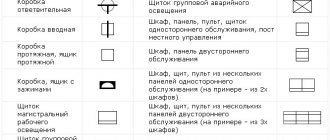
Boxes, cabinets, panels and remote controls
Among the boxes we can distinguish branch, inlet, broach, clamp. There are laboratory switchboards, regular and emergency lighting, and automatic switches. All these elements are needed to distribute electricity between individual sections of the circuit and devices. The designation conditions for these elements are presented in the picture.
Switches, switches and sockets
This includes plug sockets.
All these elements are used to switch, turn on and off electrical circuits.
This could be lighting or voltage changes. The following tables contain basic designations for this type of electrical elements.
Lamps and spotlights
Many circuits contain lamps, spotlights and other lighting elements. They are needed not only to signal certain circuit states, but also to illuminate some cases.
Monitoring and control devices
Such devices include meters, programmed devices, measuring instruments, pressure gauges, temperature controllers and time relays. Their main element is sensors sensitive to certain factors.
They have the following designations.
The article cannot contain the graphic and alphanumeric designations of all electrical devices and elements, but the most commonly used ones were discussed in detail. GOST documentation of schematic graphic designations of electrical elements on circuits of various types and types, as well as their decoding, was also described.
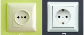
Main types of sockets
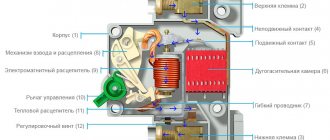
An electrical outlet (plug socket) is a device that allows you to quickly connect and disconnect various devices from the network.
Its main elements are:
- contacts – provide connection between the electrical network and the plug;
- block - ceramic housing for contacts and fastenings of the installation box (socket box);
- body - performs a decorative and protective role.
In the general sense of the word, the product can perform other functions. For example, connecting and disconnecting telephone communications, radio, Internet and even water supply in plumbing fixtures. Consequently, there are many structural and functional varieties of this type of connection.
The main types of sockets used in everyday life vary:
- depending on the installation method, there are overhead and built-in;
- by the number of nests - single or a block of two, three or more;
- by the number of connections - with and without a grounding contact;
- by purpose - antenna, for telephone and Internet, for household appliances, for powerful equipment.
The device is a surface-mounted device that is simple and universal to install. It does not require making deep holes in the wall, which is convenient for temporary placement or in industrial premises. The housing together with the block is attached to the desired surface and connected to open electrical wiring.
Since the installation is not carried out in the installation box, ordinary dowel nails are suitable for reliable fastening to the plane.
The built-in installation option has a more aesthetic appearance, since the main part of the product is immersed in the wall, and only the protective casing remains outside. Thus, nothing interferes with the perception of the interior of the room.
The wiring in this case is also rather hidden. For this type of fastening, a cylindrical hole is cut in the wall into which the installation box is mounted. It securely and securely fixes the socket in the wall.
According to the rules, it is recommended to install a device with a grounding contact at a distance of at least 500 mm from the gas pipeline
The version with two sockets is designed to connect two plugs to the network at once. With hidden installation, the block is placed in one socket box.
To increase their number (more than two), you will have to make an additional hole in the wall and combine the body with one frame if hidden installation is planned. If the model is overhead, then modular pads are added.
The European standard provides for the installation of an electric point at a height of 30 cm from the floor. This allows you to quickly find it in the dark by touch and comfortably use it for a person of average height
The modern type of socket is with a grounding contact. Used in networks with a grounding wire, which are safer than “phase-neutral” networks.
Additional terminals are attached to this wire. They first come into contact with the plug being connected, which prevents dangerous voltage and current from damaging faulty household electrical appliances. It also protects the equipment from network interference and electromagnetic interference from other devices.
The antenna has no voltage. It is used to connect the TV to the antenna cable. The only external difference is the appearance of the inlet hole in the housing.
It makes sense to place the socket block behind the TV if the location of its installation has been determined in advance, so as not to further clutter the space with cables
A computer socket is used to connect to the Internet and local networks. You can also connect a telephone cable to it.
The Internet and telephone cable connectors are the same in shape - RJ45 and RJ11/12, respectively. The first uses 8 contacts, and the second 4 or 6. But to connect to the Internet through a telephone jack, you will have to use a modem that uses a Dial-up connection.
Manufacturers of Internet cables do not recommend unwinding twisted pair cables larger than 13 mm when connecting to avoid problems connecting to the Internet.
Such devices can be made in a compact case or have the appearance of a regular 220 V. To connect a telephone with an old-style connector, you will have to install a socket with the appropriate input.
Designation of sockets and switches in drawings and diagrams
The designation of sockets and other electrical equipment is applied to the electrical circuits with the help of which installation work is carried out. Each element of the energy supply system has a designation that allows it to be identified.
The procedure for indicating symbols on diagrams is regulated by GOST. This standard was published relatively recently. The new GOST replaced the old Soviet standard. According to the new rules, the signs on the diagrams must coincide with the regulated ones.
The inclusion of other equipment in the circuit must meet the requirements of GOST. This document establishes standards for general use signs. The procedure for organizing the circuit of input distribution devices is also regulated by GOST
Designations are made in the form of graphic symbols, which are the simplest geometric objects, including squares, rectangles, circles, lines and points. In certain combinations, these graphic elements indicate certain components of electrical devices, machines and devices used in electrical engineering. In addition, the symbols represent the operating principles of the system.
Pointers on diagrams
Below is a graphic symbol that is usually used on working drawings.
Fittings are usually classified according to several criteria:
- degree of security;
- installation method;
- number of poles.
Due to different classification methods, there are differences among the symbols for connectors in the drawings.
Indicators on drawings for surface mounting
The receptacle symbols in the drawing below indicate the following characteristics.
- duality, single-pole and grounding;
- duality, single-pole and lack of grounding contact;
- single-pole, single-pole and protective contact;
- power socket with three poles and protection.
Signs for hidden installation
The picture below shows the following sockets:
- single with one pole and grounding;
- paired with one pole;
- power with three poles;
- single with one pole and without protective contact.
Symbols for waterproof sockets
The drawings use the following symbols for moisture-protected sockets:
- single with one pole;
- single with one pole and grounding device.
Socket and switch block indicators
To save space and also simplify the layout of electrical devices, they are often placed in a single block. In particular, this scheme allows you to save on gating. There may be one or more outlets nearby, as well as a switch.
The picture below shows a socket and a switch with one key.
Switch indicators with one and two keys
The picture below shows the following switches:
- external;
- invoices;
- internal;
- built-in
Below is a table showing the symbols of the fittings.
The table shows the wide range of possible devices. However, the industry produces more and more new designs, so it often happens that new fittings have already appeared, but the symbols for them are still missing.
0,00 / 0
220.guru
Designation of switches in the drawings
All switches are schematically depicted as a circle with a line on the top. One hook located at the top of the dash indicates a single-gang open type switch. Two hooks correspond to a two-gang switch. An icon with three hooks indicates a switch with three keys. (Figures 1,2)
In the case where a perpendicular strip is placed above the main line, this indicates a switch design intended for hidden installation (Figure 3). One, two or three lines correspond to a one-, two- or three-key switch.
If the circle is completely filled in black, it is an image of a moisture-resistant open type switch.
Figure 4 shows a circle intersected by a line with dashes located at the ends. Thus, pass-through switches in two positions are indicated on electrical diagrams. The circuit mirrors two ordinary switches. The number of perpendicular lines indicates the number of keys. The designation of moisture-resistant switches appears as a filled circle.
Figures 5, 6 and 7 show switches arranged together with receptacles in one block. This placement significantly saves space and facilitates installation. To connect, you only need one wire, laid in a single groove.
Figure 5 shows a regular switch connected to a standard outlet. The entire unit is designed for hidden installation. The next option (Figure 6) is more complex. It includes a grounded socket, as well as a one- and two-gang switch. Figure 7 shows a block consisting of two conventional switches and one socket.
Wiring diagram
Drawing up an electrical wiring diagram is necessary during the construction or major renovation of a house. This diagram is drawn up on a floor plan indicating the height of the cables and the installation locations of machines, sockets and switches.
This plan will be used not only by the person who compiled it, but also by installers, and subsequently by electricians who repair electrical wiring. Therefore, conventional images of sockets and switches in the drawings must be understandable to everyone and comply with GOST.
Designation of sockets on electrical diagrams
The symbol for a socket is a semicircle. The number and direction of lines extending from it show all the parameters of these devices:
- For hidden wiring, the semicircle is intersected by a vertical line. It is absent in devices for open wiring;
- In a single socket, one line goes up. In doubles there is a double dash;
- A single-pole socket is indicated by one line, a three-pole socket by three, diverging like a fan;
- Degree of protection from weather conditions. Devices with IP20 protection are depicted as a transparent semicircle, and with IP44-IP55 protection, this semicircle is painted black;
- The presence of grounding is indicated by a horizontal line. It is the same in devices of any configuration.
Symbol of sockets in the drawing
Interesting. In addition to electrical outlets, there are computer outlets (for the LAN cable), television outlets (for the antenna), and even vacuum outlets, to which the hose from the vacuum cleaner is connected.
Designation of switches on diagrams
The switches in all drawings look like a small circle with a line tilted to the right at the top. There are additional lines on it. By the number and type of these lines, you can determine the device parameters:
- a hook in the shape of the letter “G” is a device for open wiring, a transverse line in the shape of the letter “T” is for hidden wiring;
- line one - single-key switch, two - two-key, three - three-key;
- if the circle is filled in, then this is a device with a weather protection rating of IP44-IP55.
Symbol of switches
In addition to regular switches, there are pass-through and cross switches that allow you to control the light from several places. The designation of such devices in electrical circuits is similar to the usual ones, but there are two slashes: right-up and left-down. The symbols on them are duplicated.
Designation of switch block with socket
For ease of use and a more aesthetic appearance, these devices are installed in adjacent mounting boxes and covered with a common lid. According to GOST, such blocks are designated by a semicircle, the lines on which correspond to each device individually.
The following figure shows two examples of switch and socket blocks:
- design for hidden wiring from a socket with a grounding contact and a double switch;
- design for hidden wiring from a socket with a grounding contact and two switches: double and single.
Designation of switch block with socket
Symbols of other devices
In addition to sockets and switches, electrical wiring diagrams also use other elements that have their own symbols.
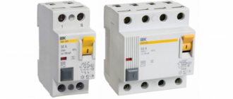
The designation of protection devices: circuit breakers, RCDs and voltage control relays is based on the image of an open contact.
The designation of a circuit breaker according to GOST consists of the required number of contacts connected to each other and a square on the side. This symbolizes the simultaneous operation of the protection system. Input circuit breakers in apartments are usually two-pole, and single-pole ones are used to disconnect individual loads.
Circuit breaker on conventional and single-line diagrams
There are no special designations according to GOST for RCDs and differential circuit breakers, so they reflect the design features. Such devices are a current transformer and an executive relay with contacts. In automatic machines, a circuit breaker for protection against overload and short circuit is added to them.
Image of RCD and differential circuit breaker in diagrams
The voltage control relay turns off electrical appliances when the voltage deviates beyond acceptable limits. Such a device consists of an electronic board and a relay with contacts. This can be seen in the diagram of such devices. It is depicted on the top cover of the case.
Voltage control relay circuit
Graphic symbols of lighting and illumination devices, including LED chandeliers, symbolize the appearance and purpose of the devices.
Symbols of lamps
Knowledge of the symbols of sockets and switches and other equipment on the drawings is necessary when drawing up a project, installing and repairing electrical wiring and other electrical equipment.
Rules for the design of drawings
When preparing drawings, you should pay close attention to five key aspects:
- sheet format and design;
- scale;
- lines;
- dimensions;
- fonts.
Practice shows that students make the largest number of mistakes when applying dimensions and other designations on drawings. To avoid any misunderstanding, let's look at each aspect in more detail.
Sheet format and design
Drawings are drawn up on sheets of a certain size. In educational institutions, A4 sheets are most often used, the parameters of which are 297 * 210 cm. The requirements for other sheet formats according to GOST are as follows:
The A4 format is placed exclusively vertically, unlike other main formats.
Frame
First of all, you should draw a frame that defines the boundaries of the drawing. Margin size: top, right, bottom – 5 mm from the outer edge of the sheet, left – 20 mm (this distance is used for filing the drawing). The frame is designed with solid thick lines, which can be easily drawn with a soft pencil, indicated by the letter B.
Sample frame design:
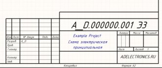
In the lower right corner is the main inscription of the drawing, which sets out key information regarding the drawn object and the author of the drawing.
Main inscription
The main inscription is present in all drawings without exception, regardless of format, scale, content, etc. It is located in the lower right corner of the sheet and is drawn with solid thick lines.
In educational institutions, the main inscription contains the following data:
- The name of the object that is presented in the drawing. For example, “steering wheel”. If the product name consists of several words, the noun comes first. For example, “the steering wheel is round.”
- Designation (number) of the drawing according to GOST 2.201-80. For example: UZ.KCh0213.011, where UZ is an educational institution, KCh is a drawing course, 02 is building number two, 13 is option thirteen, 011 is the serial number of the product.
- Designation of the part material. This column should be filled out only if the drawing shows a part.
- A letter that is assigned to a document. For example, the letter “U” is used for educational drawings.
- Product weight. Described in kilograms.
- Image scale.
- Serial number of the sheet.
- The total number of sheets that were drawn during the semester.
- Name of the educational institution (for example, TSU) and group number.
- Nature of the work.
- Last names of the student and teacher.
- Signatures of the student and teacher.
- Date the drawing was signed.
Sample title block design:
Scale
In practice, you may be faced with the need to draw up a drawing of very large products (for example, an airplane, a house, a ship, etc.) or very small ones (a part of a clock mechanism, part of a computer motherboard, etc.). Large life-size images do not fit on the sheet, and small ones cannot be drawn, since they are barely visible to the naked eye. It is in such cases that a scale is used, allowing small details to be enlarged and large ones to be reduced.
Scale is the ratio of the image dimensions in the drawing to the actual dimensions of the object. The scales of images and their designation in the drawings are standardized.
The standard allows the use of the following scales:
- Natural size – 1:1. This scale is used in rare cases, although it is the most convenient and simplest, since you can immediately understand what the actual size of the object is.
- Reduction scale – 1:2; 1:2.5; 1:4; 1:5; 1:10; 1:15; 1:20; 1:25; 1:40, etc. This type is used for very large objects.
- Magnification scale – 2:1; 2.5:1; 4:1; 5:1; 10:1; 20:1; 40:1; 50:1; 100:1. This variety is used to depict small items.
- Specific reduction scales are calculated using certain formulas. In particular, they are used for drawing bridges, factory facades, etc.
- Special scales of increase are also determined using special formulas. They are used for microscopic products.
The scales are written as follows: M1:2, M5:1, M1:1, etc. It is indicated next to the object.
An example of indicating the scale in a drawing:
Lines
When making drawings, lines of various thicknesses and styles are used. Each of them has its own purpose and features.
- Solid thick main line . Used to depict visible contours of objects, frames and graphs of the main inscription of the drawing.
- Dashed line . Used to depict invisible contours of an object.
- Dash-dotted thin line . This line divides the image into two equal parts. With its help, the axes of rotation and the center of circular arcs are shown.
- Solid thin line . Used for drawing extension and dimension lines.
- Dash-dotted thin line with two dots . Used when constructing flat patterns for a fold line.
- Solid wavy line . As a rule, it is used as a break line in cases where the image is too large and does not fit on one sheet.
Dimensions
Dimensions are used to determine the dimensions of an object.
- Angular dimensions . Demonstrate the magnitude of the angle between two lines, indicated on dimension lines and callouts in minutes, seconds and degrees.
- Linear dimensions . Used to determine the length, width, height, diameter, thickness and radius of an object or part of it. These dimensions are indicated in millimeters, without a unit of measurement.
Product dimensions are always shown as actual, regardless of the image scale.
Sample of dimensions in the drawing:
Fonts
When drawing up drawings, a special font is used with parameters specified by GOST, which determine:
- the size and inclination of letters and numbers to the base of the line;
- thickness of font lines;
- distance between characters.
Drawing fonts for students for Word according to GOST
Symbol of the socket on the diagram
One of the most common elements of a home's electrical system is the electrical outlet. On the diagram it may look like different symbols, which depend on the type and design of this device.
The most important stage in arranging electrical wiring is drawing up a plan for the placement of all its elements.
Proper application of all components of the electrical network to the electrical diagram ensures correct planning of the required amount of materials, as well as a high level of electrical safety.
Advice
A correctly drawn up diagram greatly facilitates the selection of the types of equipment needed.
The electrical wiring plan is drawn up taking into account the scale of the premises and the features of its layout.
Guiding Documents
In order to unify the symbols used in electrical circuits, GOST 21.614-88 “Conventional graphic images of electrical equipment and wiring on plans” was adopted back in Soviet times.
In accordance with this document, the simplest geometric shapes are used to designate all elements of the electrical network, making it easy to apply and also identify a particular element on an electrical circuit.
Strict requirements for the execution of such drawings eliminate confusion and double interpretation of all symbols printed on the diagram, which is extremely important when performing installation work in the electrical network
Designations of elements of an open installation
The simplest two-pole electrical socket of open installation without a grounding contact is depicted on the electrical diagram in the form of a semicircle with a line drawn perpendicular to its convex part.
The designation of a double socket differs from the previous one in the presence of two parallel lines. The graphic symbol corresponding to a three-pole product is a semicircle, the convex part of which is adjacent to three lines converging at one point and arranged like a fan.
Sockets for hidden electrical wiring
Concealed wiring is the most common type of home electrical network. To install it, devices are used that are built into the wall using special mounting boxes.
The only difference between the designation of such rosettes and the above figure is the perpendicular, lowered from the middle of the straight segment to the center of the circle.
Devices with increased protection from dust and moisture
The sockets considered do not have a high level of protection against the penetration of solid objects into their housing, as well as moisture. Such products can be used in interior spaces where operating conditions exclude such effects.
As for devices intended for installation outdoors or, for example, in bathrooms, according to the accepted classification, their degree of protection should be below IP44 (where the first digit corresponds to the level of protection against dust, the second - against moisture).
Such sockets are indicated on the diagram in the form of a semicircle completely shaded in black. As in the previous case, two-pole and three-pole waterproof sockets are indicated by the corresponding number of segments adjacent to the convex part of the semicircle.
Switches
The switch in the diagram is indicated in the form of a circle, to which a line is drawn at an angle of 45 with an inclination to the right side, having one, two or three perpendicular segments at the end (depending on the number of keys of the switch depicted).
The image of the hidden installation switches is the same, only the segments at the end of the inclined line are drawn in both directions from it at the same distance.
It is worth paying attention to the image of pass-through switches, which resembles two ordinary switches, mirrored from the center of one circle
Socket blocks
Often, in terms of a home electrical network, it is necessary to provide for the installation of blocks that include different numbers of the most common elements - sockets and switches.
The simplest block, containing a two-pole socket and a single-key hidden switch, is depicted in the form of a semicircle, from the center of which a perpendicular is drawn, as well as a line at an angle of 45, corresponding to the single-key switch.
Blocks containing different numbers of sockets and switches are drawn on the diagram in a similar way. For example, a hidden installation unit, which includes a two-pole socket, as well as one-key and two-key switches, has the designation:
Regulations
Standards regulating the compliance of designations used in technical documentation with elements of real electrical circuits were developed back in Soviet times. The main working document defining the rules for their introduction is GOST 21.614-88 “Conventional graphic images of electrical equipment and wiring on plans.” Since 2009, another version of the standards has been put into effect in our country under the designation GOST 2.701-2008 “ESKD. Scheme. Types and types. General requirements for implementation."
In accordance with these regulatory documents, the simplest geometric figures are used as suitable graphic images of real electrical circuits and their elements, namely:
- regular squares;
- circles, semicircles and truncated ovals;
- arbitrary rectangles, as well as points and lines of a given thickness.
Taken in various combinations, these elements completely cover the entire range of equipment used in electrical engineering, together with the circuits that control its operation. Based on them, it will be possible not only to find out how standard electrical installation products are schematically designated, but also to draw any electrical circuit yourself.