How to Install a Lamp Cord Switch | Home Guides
The most common types of lamps come with a switch next to the lamp socket, or they do not have a switch and are controlled by a wall switch after they are plugged into the socket. But some types of lamps, such as string lights, decorative lamps, or pendant lamps, are controlled by a switch on the lamp cord. These switches are almost always a rotary type switch that connects to the lamp's electrical cord; you turn them on by turning the switch wheel with your thumb.
Before starting work, remove the plug from the outlet. Never work with the cord connected.
Determine which wire is hot. Each cord has two wires coming from the plug. The smooth side, with no protrusions on the sheath covering the wire, will be the hot wire. This is the wire that will be used.
Determine where you want to install the switch. Make sure it is located along the cord in an easily accessible location to turn the light on and off. Where the switch is to be inserted, measure a 3/4 inch line. Mark the two ends with a permanent marker.
Place the blade of a utility knife through the center of the cord and into one of the marks. The center of the cord between the two wires will be slightly jagged. Press the tip of the blade into the plastic and separate the cord from mark to mark. Follow the recessed area exactly the same way you make this cut.
Cut the hot wire in half with wire cutters. Leave the second wire intact.
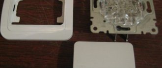
Unscrew the line switch with a small screwdriver. Pull it apart and mark the top and bottom with a permanent marker. This is important because the switch must be reassembled exactly the same way it was disassembled. Set the side with the rotary switch aside. The hollow side of the switch is the side that will be used.
Place the cord inside the hollow rotary switch housing. You will see two channels in the body. The intact wire will go into a free channel, and the cut wire will go into a channel divided in the middle by a plastic partition. Each end of the cut wire will rest against the plastic partition, so that there will be no connection between them. There is no need to strip the wire in this application.
Reassemble the switch in the same form in which it was disassembled. Tighten the screws on the switch housing securely. It is important. When you tighten the screws on the switch body, two pointed copper "arrows" will pierce the cut wire inside the switch and make an electrical connection. The connection will only be activated when the rotary switch is turned.
Connect the lamp and check. If the lamp does not light, unplug the lamp and retighten the switch housing screws.
.
How to Wire a DIP Switch (with Diagram)
In this tutorial, we will show you how to make a 2-way patch connection . A two-way switch connection means that you can control electrical equipment such as a light bulb using two switches located in different locations, typically found on stairs. The two-way switch can be controlled independently of any switch, which means that no matter the position of the other switch (ON/OFF), you can control the light with the other switch.
There are two methods to connect to 2-wire switching : one is 2-wire control and the other is 3-wire control . We have explained both methods below and both methods are demonstrated in the Video given at the end of this article.
Required Components
- Two DIP Switches
- Lamp
- AC power supply
- Connecting wires
How to Wire a DIP Switch Using Two Wire Control
This is the first two-way switching method, it is the old method. If you are going to install a new one, use the three-wire control method.
As you can see in the 2 way switch circuit diagram below , you will find that the phase/voltage is connected to the common wire of the first 2 way switch. PIN1 and PIN2 of the first switch are connected to PIN1 and PIN2 of the second switch, respectively. One end of the lamp is connected to the common terminal of the second switch, and the other end of the lamp is connected to the neutral line of the AC power source.
Note: Under 2-wire control method, when the switches are in the opposite state , the light will be in the off state , as shown in the diagram below:
The condition for obtaining the output in ON state is the same as in the Ex-nor truth table which is given below:
| Switch 1 | Switch 2 | Lamp status |
| 0 | 0 | 1 |
| 0 | 1 | 0 |
| 1 | 0 | 0 |
| 1 | 1 | 1 |
Where 0 represents the OFF state and 1 represents the ON state.
How to Wire a DIP Switch with a Three Wire Control
This is a new method for creating a two-wire switching connection because it is slightly different from the two-wire control method. This method is commonly used these days because it is more efficient than a two-wire control system.
As you can see in the DIP switch circuit diagram number , the common circuit of both switches is shorted. PIN1 of both switches is connected to the live phase or live wire and PIN2 of both switches is connected to one end of the lamp. The other end of the lamp is connected to the neutral of the AC source.
Note: Under 3-wire control method, when the switches are in the same state , the indicator light will be off as shown in the diagram below:
The condition of obtaining the output in ON state is the same as in the explosion-proof or logic gate truth table given below:
| Switch 1 | Switch 2 | Lamp status |
| 0 | 0 | 0 |
| 0 | 1 | 1 |
| 1 | 0 | 1 |
| 1 | 1 | 0 |
Where 0 represents the OFF state and 1 represents the ON state.
Application of two-way switching:
- Mostly on the staircase.
- Faulty operation of safety/circuit protection devices.
- Large hall with two entry/exit gates.
- To control any AC appliances such as fan or light from two places such as input and output.
.
Installation of a two-key switch
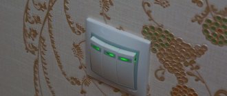
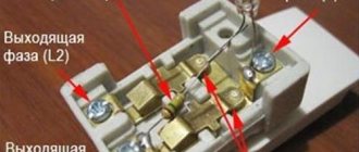
Legrand two-key pass-through switches are distinguished by the presence of a pair of contacts that are independent of each other. When you press the keys, they switch the upper lines to the lower ones, and at the same time the upper contacts are made with the absence of a final output. And the lower contacts are connected to the second, same pass-through switch.
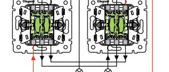
Knowing how the left and right groups of contacts are arranged, it is easy to understand how to connect a pass-through switch.
Connecting a pair of pass-through switches is extremely simple. The phase that leaves the electrical panel of the apartment or house is supplied to the contact of the second switch, while within the entire group the contacts are connected to each other by a jumper. And those contacts that are in the left group supply current to lighting devices independent of each other. It is important to consider one rule here. Under no circumstances should these two contacts be connected to each other. Then all four cross contacts need to be linked together as a pair.
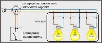
How to control a light bulb with a one way or one way switch?
How to connect a light switch? Controlling the lamp with a one-way switch
In today's basic home wiring installation guide, we'll show you how to wire a light switch to control a light point using a one-way or one-way switch.
In this tutorial, we will use a basic SPST (Single Pole Single Pole) to control a lamp/light bulb from one location.
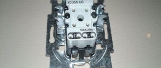
Before going into details, we must show the basic structure and working mechanism of a one-way switch , which is shown in the figure below:
Design and Operation of Single Pole Single Pole Switch
a simple step by step guide with diagram and wiring diagram that shows how to wire a light switch to control a light bulb/lamp from one place using a one way or one way switch?
Requirements:
- Single Pole Switch (SPST = Single Pole Through) x 1 No
- Lamp (bulb) x 1 No
- Short cable lengths x 3 No
Procedure:
This is similar to a sequential circuit i.e. all components are connected in series. Simply connect the neutral wire directly to the bulb and then connect the bulb to the switch via the middle wire. Then connect the live wire to the switch as shown in the picture below. The figure below shows the basic light switch connections and their positions i.e. when the switch is off, the circuit acts as an open circuit and the light bulb does not light up. To turn on the light bulb, switch S 1 must be closed to complete the circuit and heat the light bulb.
Connecting the light switch
In Fig. Below are the circuit diagrams and wiring diagrams of light switches which show how to wire a light switch?
How to connect a light switch
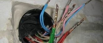
Also note that house wire colors may vary by area. Also, always use and connect a ground wire (straight bare wire to switches and electrical appliances from the ground in the distribution panel to reduce the risk of electric shock and hazard) that is not shown in the pictures above.
Good to know:
- Switches and Fuses must be connected across the line (live).
- Connecting switches in series is not the preferred way to connect appliances. parallel or series-parallel connection method is more reliable.
- This type of wiring requires fewer wires and cables.
Warning:
- Electricity is our enemy, if you give it a chance to kill you, remember, they will never miss it. Please read all the precautions and instructions when putting this guide into practice.
- Disconnect the power source before servicing, repairing, or installing electrical equipment.
- Never attempt to operate on electricity without proper guidance and care.
- Work with electricity only in the presence of persons with good knowledge, practical work and experience who know how to handle electricity.
- Read all instructions and warnings and follow them strictly.
- Contact a licensed electrician or utility company before making any changes to electrical connections.
- The author is not responsible for any loss, injury or damage resulting from the display or use of this information, or if you try any diagram in an incorrect format. So please! Be careful because it's all about electricity and electricity is too dangerous.
Tutorials for installing appropriate electrical wiring:
.
Operating principle of pass-through switches
Externally, an ordinary switch is practically no different from a pass-through switch, and it is impossible to visually distinguish them without revealing the design. The difference lies in the internal structure. A regular switch opens or closes a circuit carrying electric current, while a pass-through switch, connecting one line, disconnects the other. That is, in other words, when the pass-through switch is operating, no matter which pair of keys is pressed, the switch is ready for operation. We pressed the left one on one switch and the light went out. We pressed the second one on it, or the key on the second switch - the light comes on again. This is undoubtedly very convenient.
In other words, for a regular single-key switch both contacts are working, but for a pass-through switch there are as many as three. Because the second contact, which acts as an output contact, is connected to the second switch, a pair. And when connecting two-key pass-through switches, the number of contacts increases to six.
If you carefully examine the connection diagram below, you can easily cope with the installation of any pass-through switches and install all the necessary devices so that the circuit functions normally. The main thing is to follow safety precautions, not to work when the mains voltage is on, and to make sure that a workable circuit is used.
2-position switch - how to control one lamp from two or three places?
Two-Way Connection - Electrical Connection Diagrams
What is two-way switching?
Two-way switching connection is used to control electrical appliances and equipments such as fan, lighting points, etc. from different places using two-way switches. The most common use of a two-way switch connection is in staircase wiring, where a light point can be controlled from two, three, or even many locations. Regardless of the current position of the two-way switch (ON or OFF), a connected appliance, such as a light bulb, can be turned on/off by pressing a button.
Two or three way switch?
Two-way or three-way switch : "Three-way" is the North American (US) term for this type of switch and is used in the following manual. Most English speaking countries (UK/EU) call them "bilateral". The term for the pair of wires connecting two switches also varies: "ties" for the UK and "travelers" in the US.
Please don't kill me to mention this 2 way switch instead of 3 way switch as whatever we used is the same for the specific purpose.
Design and operation of a two-position switch
A double throw switch
is also known as a single pole double throw (SPDT) switch. The basic structure and working principle of a two-way switch is shown in (Figure 1) below.
Design and operation of SPDT (single pole, double pole) switch
How to Wire a DIP Switch
Below is a circuit diagram (Figure 2) that shows how to wire a two-way switch. switch and control the light bulb from two different places.
Note:
- The same goal can be achieved by using the following two-way switch connection shown in Fig.
- Connect the grounding wire to the connected electrical appliance as well as to the switches in accordance with the electrical codes of your region.
How to control a light from two places using a 2 way switch?
The following two-way dial-up connection can be used for the same purposes as those mentioned above in Fig. 1 i.e. to control the light point from two different locations using dip switches
How to control one lamp from three places using DIP switches?
In Fig. Figure 4 wiring diagram shows how to control the light point from three different locations using two dip switches and an intermediate switch.
In Fig. Figure 5 shows the same connection to control a light point from three locations using different symbols.
Two-way switching to control lighting from two places on the stairs
As we discussed above, the most common use of two way switches is to control a light point from different locations such as upstairs and downstairs i.e. front door and upper door. This diagram is shown below:
How to control lights from six places
Below is a wiring diagram that shows how to control a light point from six different locations using two DIP switches and four intermediate switches. Note that you can control even more light bulbs by adding more intermediate switches in the middle of the circuit.
Application of two-way switching
- It is used to control electrical equipment and appliances from two, three or even more different locations by adding additional intermediate switches.
- It is also used in staircase wiring where the light point can be controlled from two or more different locations.
- Used in large premises with two or more entrance and exit doors and gates.
- The main purpose of two-way switching is to control an AC or DC electrical appliance, device or equipment, especially light points, from two places.
You can also read:
.