How to properly connect machines and RCDs
Before starting work on connecting the machines, it is necessary to prepare all the devices:
- Mounting rail (sometimes it is already included with the finished shield). In other cases, you will need to measure the required length yourself and cut it with metal scissors.
- Screwdriver.
- Wire cutters.
- Wire stripper.
Connecting machines and RCDs - step-by-step instructions
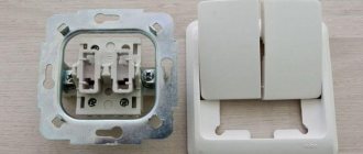
Step 1. To begin, you should attach two buses to a metal DIN rail: neutral and ground. This is easy to do; you just need to insert them at one end and then snap them into place.
This is what the tires should look like after installation.
Step 2. Now you need to secure the machines in series. At the bottom they have a special latch, which you just need to pull down and then secure the machine to the rail.
Each machine must be secured to the rail one by one.
Step 3. Next you need to take a three-core cable. As a rule, the ground wire is yellow, the neutral is blue, and the phase is white or pink (as in our case).
It is important not to mix up the power cable wires
Step 4. First we need to connect the neutral wire to the neutral bus. This is easy to do - you just need to unscrew the bolt with a screwdriver.
There is a hole for cables of different sections
Step 5. Now you need to connect the yellow ground wire to the ground bus.
This is done in the same way as in the previous version.
Step 6. The next step is to secure the power wire (pink). Contrary to many opinions, it should always come from the top. You should connect the wire, but you shouldn’t tighten it right away - the reason is that you will then have to supply the power wire to all other machines.
In this step, the wiring is connected “live”
Step 7. Seventh: you need to insert the power wire into the upper machine, and then insert one end of the additional jumper into the same hole.
Now you need to insert the jumper into the adjacent machine, and then into the other, alternately tightening the screws
Step 8
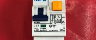
Now you need to pay attention to the last differential machine. On its body, as a rule, there is a connection diagram. The first input here will be designated by the letter N - this will be zero, the second input will be designated as I (L) - this will be the phase
The first input here will be designated by the letter N - this will be zero, the second input will be designated as I (L) - this will be the phase.
Step 9. Now it has become clear that the phase is at the second input, which means that the other end of the yellow jumper wire should be secured there. We tighten the screw by analogy with the previous options.
Thus, we have completed connecting the power cable that comes from the shield
Step 10. Now you need to connect the wires that come from the room. First, you will need to remove the insulation layer from their ends. A special tool is used to strip the ends of the wires.
Here you can turn the screw and set the wire thickness
Step 11. Here you should also connect the neutral wire to the corresponding bus.
You can unscrew any loose bolt
Step 12: Now you need to secure the ground wire again.
The wire must be tightened carefully, without catching the insulation layer.
Step 13. Now from below we fix the power wire that comes from the electrical device.
The following wiring, by the same analogy, will be connected only from below
Step 14. Now you need to take an additional wire, connect it to the zero bus, and then to the first input on the differential machine.
We fix the wire in the first hole of the difavtomat
Connection errors: how to avoid them
The question is often asked: how to connect an RCD correctly so that the circuit works without failures? As an answer, the following are the most typical miscalculations when connecting protective equipment without grounding.
- Interweaving of neutral conductors coming out of the device into a single unit. This provokes unreasonable alarms and makes it difficult to check the correct installation. To make sure that the assembly procedure without grounding is followed, plug the electrical appliance into the socket connected to the RCD. If it works, the circuit is assembled correctly.
- Connecting the grounding wires of sockets to the neutral wire of the RCD or to a homemade grounding circuit. This violates electrical safety standards: an amateur circuit often causes a short circuit. When connecting the grounding switches of the sockets to water supply or heating pipes, an electric shock can strike not only the people living in the apartment, but also their neighbors.
- Neutral and ground connection. In this case, the RCD simply will not operate, since it works due to the difference in current strength in the phase and neutral wires. The connection between zero and ground provokes stable power outages in the apartment. If the grounding circuit does not work, then the grounding wires from the devices coming to the electrical panel should be wrapped with insulating tape: otherwise, the conductive parts of the household appliances may be exposed to dangerous voltage.
How to properly connect an RCD. demonstrates a video clip that details the sequence of all operations - thanks to the visual lesson, even a non-professional can easily cope with installing single-level protection. If the circuit is more complex, requires the coordinated operation of several protective devices, and is associated with a grounding connection, it is better to order installation by a professional electrician - so as not to be constantly without power and to operate electrical appliances safely.
Purpose and operating principle of RCD
First of all, let's consider why this device is needed and for what purpose it is placed in the mains supply line. An unprofessional approach to these issues gives the impression that one circuit breaker is sufficient to reliably protect power lines. But ouzo is required in order to protect humans and animals from electric shock in the presence of its leaks.
A feature of devices of this class is their high sensitivity to very small currents, amounting to fractions of an ampere and always present in places of high humidity or damaged insulation. That is why installing an ouzo is the most reliable way to protect living organisms (including pets) from possible electric shock in a number of hazardous areas, found not only in city apartments, but also in private residential buildings.
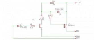
The operation of an RCD is based on the principle of comparing currents in a special differential unit with a direct and reverse tap from a single-phase line inserted into it (its inclusion in the supply circuit is shown in the figure below).
Let us consider the essence of the functioning of this device in more detail in the form of the following sequence of its states:
- In normal (standard) operating mode, forward and reverse currents flowing through the differential unit have the same amplitude values. In this case, the protective devices do not react in any way to changes in currents in the line, since the magnetic fields created by the inductive coils are mutually compensated (the currents through them are equal in magnitude);
- If there is a leak through a living organism (its value is measured in microamperes), a current difference appears in the differential or comparing unit, disturbing the balance of magnetic fluxes F1 and F2;
- The consequence of this is the formation of a control pulse supplied to the executive relay, which disconnects the line from the consumer (load).
Note! The speed of such shutdowns or actuation of the executive relay is usually calculated in fractions of seconds (more precisely, microseconds). In such a short time, current processes do not have time to spread throughout the body of a living organism, which means one hundred percent protection from electric shock
In such a short time, current processes do not have time to spread throughout the body of a living organism, which means one hundred percent protection from electric shock.
Is it necessary to install RCDs on sockets?
It may seem to you that this is completely banal, but let’s approach this issue more seriously with justification by regulatory documents. I constantly come across different people: some want to install RCDs everywhere, others don’t want
If you don’t want to deal with this issue, then install an RCD on all socket groups and 95% of the time you won’t be wrong.
The main regulatory documents that impose requirements for the installation of RCDs:
TKP 45-4.04-326-2018 (Electrical equipment systems for residential and public buildings).[1]
SP 256.1325800.2016 (Electrical installations of residential and public buildings. Design and installation rules). [2]
SP 6.13130.2013 (Fire protection systems. Electrical equipment). [3]
GOST R 50571.3-2009 Low-voltage electrical installations. Part 4-41. Security requirements. Protection against electric shock.[4]
There is something else in TKP 339-2011. We will not take SP 31-110-2003 into account, since SP 256.1325800.2016 is considered more important and reference to SP 31-110-2003 can only be made to the extent that does not contradict SP 256.1325800.2016. The PUE is also a rather dubious and ancient document, mostly recommended. Yes, and Appendix A from SP 256.1325800.2016 is recommended
It should be borne in mind that the RCD is only an additional protective measure.
Let's go through the basic requirements and recommendations:
16.3.2 Installation of RCDs is prohibited for electrical receivers, the disconnection of which can lead to dangerous consequences (disconnection of building safety systems, loss of information, creation of an immediate threat to human life, explosions, fires, etc.).
Installation of RCDs in lines supplying permanently installed equipment and lamps, as well as in general house lighting networks, is not required, except for those specified in 16.3.4. Permanently installed electrical equipment, even if it is connected via plug connectors, includes electrical equipment weighing more than 18 kg that does not have rollers for movement, as well as permanently fixed electrical equipment, regardless of the weight and presence of rollers. [1]
A.1.6 The need to use UDT is determined by the design organization based on ensuring safety in accordance with the customer’s requirements and duly approved standards and other regulatory documents.
A.4.11 UDTs, as a rule, should be installed in group networks that supply plug sockets. Installation of UDTs in lines supplying permanently installed equipment and lamps, as well as in general building lighting networks, is usually not required.
A.4.13 The installation of UDTs that operate to disconnect is prohibited for electrical receivers, the disconnection of which can lead to dangerous consequences: creating an immediate threat to human life, causing explosions, fires, etc. [2]
4.13 It is prohibited to install residual current devices or switches controlled by differential (residual) current, including those with built-in overcurrent protection, in the power supply circuits of SPS electrical receivers. [3]
411.3.3 Additional Protection On a.c. systems, additional protection by means of a residual current protective device (RCD) in accordance with 415.1 shall be provided for: - receptacles intended for general use, with a rated current not exceeding 20 A, used by general persons. . Note 1: An exception may be made for: - socket-outlets intended for use under the supervision of qualified or instructed personnel, for example in certain commercial or industrial premises, or - a special socket-outlet intended for the connection of a single electrical appliance. Note 2 - In Spain and Ireland, additional protection is provided for socket-outlets with a rated current of up to 32 A intended for use by ordinary persons; - mobile equipment with a rated alternating current not exceeding 32 A, which is used outside the building. (Dokipedia: GOST R 50571.3-2009 Low-voltage electrical installations. Part 4-41. Safety requirements. Protection against electric shock).[4]
And now I want to share my thoughts and design experience.
Almost always I try to install RCDs on socket groups. Yes, an RCD is not a cheap product, but it really increases the level of electrical safety and fire safety.
However, our standards say that it is not always necessary to install an RCD.
Connecting electrical appliances
Let's look at a few examples.
1 Fire and security alarm devices, video surveillance.
By and large, it is not worth installing an RCD on these lines because These devices are safety related and are stationary devices.
A socket is just a switching method.
2 Air conditioning.
I almost always install an RCD on the air conditioner. Who knows what will be connected: air conditioning or something else. In my opinion, the air conditioner is also a stationary equipment and the RCD need not be installed. Moreover, the outlet for the air conditioner is usually installed under the ceiling and is inaccessible to others. Those. both the socket and the air conditioner are out of reach.
3 Electric stove.
In the Russian Federation I do not install RCDs. In the Republic of Belarus the question is controversial, you can raise it, or you can not raise it, but it’s better to raise it.
4 Heat meter.
Previously, I always installed an RCD. I haven’t installed it in recent projects, I’m waiting for comments from the expert. The heat meter is also a stationary device.
5 Sockets in residential buildings during major renovations.
In my course on designing private housing, I touched on this topic in some detail. The bottom line is that in old houses, sometimes 2 groups can have a common zero, which means that RCDs in these groups will not work. Therefore, installing an RCD in old housing stock is not always possible.
6 Computers.
Recently I was asked whether it is necessary to install an RCD on the socket groups of computers in the administrative building. If computers are not related to banking activities, then I always install an RCD, but with banks you need to deal with it... In my opinion, if there is a risk of losing information, then the computer should have an individual UPS.
Where else don’t you install an RCD?
PS If we talk about private houses, then I would install an RCD in almost all groups. In order to save money, one RCD can be used for 3 groups.
I recommend reading:
#3 Analysis of the expert’s comments on the power electrical equipment project
Diesel generator set redundancy
Cable selection for TSPPZ
5 mistakes of a typical project
Connection in an apartment and in a private house
For a washing machine,
the connection diagram in the apartment is carried out only via a single-phase network. For this reason, the connection is made in the following order:
Connection in the apartment
If you have power consumers of electricity in your apartment, for example, a washing machine or an electric oven, then it is recommended to additionally connect an RCD protective device.
As for connecting the machine in a private house, the connection sequence is as follows:
- Introductory machine.
- Electricity meter.
- Automatic from 100 to 300 mA, the choice is made depending on the amount of current consumed by all household appliances.
- Automatic machine for individual current consumption. Typically, 10 to 30 mA is used.
So, we have examined with you some of the features and differences of connecting an RCD in certain circumstances. Most importantly, remember that if you have no idea at all about this system, then it is better not to experiment.
A few words about typical errors when connecting an RCD:
To correctly install the RCD, we suggest that you familiarize yourself with some of its connection diagrams:
Residual current device
Connecting an RCD with automation
Connection to 380V network
Four-pole RCD without zero
Apartment group panel
1. Connecting a four-pole RCD to a three-phase network using a neutral. Your diagram shows a single-phase network. Above the green wire the inscription is blue. This wire should be yellow-green. 2. Connecting a four-pole RCD in a single-phase network. The figure shows a two-pole (single-phase) RCD.
Alexander! Thank you very much for your relevant comments. These shortcomings will be eliminated in the near future. We apologize for any inaccuracies in the illustrations posted.
- How to connect a washing machine with your own hands
- Instructions for replacing heating elements in a washing machine
- How to make an electric heated floor
- Operating principle of the air conditioner
Video about installing electrical wiring yourself
Why and what kind of RCD should be installed at the entrance to the apartment?
In 123 Federal Law, Article 82, paragraph 4, we are not talking about the building as a whole, but about the premises, therefore the requirements for installing a residual current device at the entrance to the building, for example in an ASU, are not justified, since they do not comply with the instructions in paragraph 4 of Article 82.
The paragraph does not indicate the type of residual current device, therefore the requirements for the mandatory installation of an RCD-D have no basis; paragraph 4 refers to a certain device that performs a specific function.
The concept of “room” includes both a living room and a factory workshop. It is obvious that the construction of networks of these objects is radically different.
Electrical equipment can become a source of fire for several reasons:
short circuit in equipment and electrical wiring. Protective shutdown in this case is provided by a circuit breaker or a fuse;
overloading of equipment and wires and/or electrical cables. Protective shutdown in this case is provided by a circuit breaker release with an inverse time-current characteristic or, in some cases, by a fuse;
excess leakage due to deterioration of insulation. Protective shutdown in this case is provided by a residual current residual current device or an insulation monitoring device.
The use of a particular protective device is determined by the conditions of use and the type of protective grounding system, and all this applies only to electrical installations with voltages up to 1 kV. F
And here is an answer, an explanation on this matter from the developers of this Federal Law
In technology, the concept of “residual current devices” unites the entire set of technical devices designed to perform the protective functions of various products. In relation to electrical engineering, these are devices that provide protection against overcurrents, overvoltage, leakage currents, thermal protection, against exceeding explosive concentrations of gases, etc. Federal Law FZ-123... establishes the need to use protective shutdown devices against the occurrence of fire hazardous conditions in electrical installations. Examples of such devices could be: circuit breakers, fuse links, surge protection devices, residual current controlled circuit breakers and many others. As for circuit breakers controlled by differential current, along with the abbreviation RCD according to GOST 12.4.155-85 (2003) SSBT, according to GOST 50807-95 they are designated as “UZO-D”, and according to GOST... as AVDT. Therefore, do not mislead people, what kind of protection device to install, the input machine, or ouzo, or differential automatic machine, is chosen by the designer or the owner of the house, the main thing is that one of these devices should be at the input. There is no indication exactly which one.
Two-phase electrical network: how to connect an RCD
First, it’s worth understanding why it is necessary to install protection in two-phase circuits. These are primarily observed in apartments located in old buildings, and in such conditions, additional safety is necessary, since more often in such housing there is no grounding, and current leakage in places where it should not exist often leads to a fire.
Let's talk about a single-level security system
The connection option is too simple at first glance, however, taking into account the nuances is important for complete safety
- The most powerful device is selected;
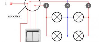
- The installation must provide for the transfer of current to the machine, and from it to all devices, including light bulbs and sockets;
- The design of this circuit is compact and elementary.
It is customary to install single-level protective devices on one device, too, for example, for a washing machine or water heater. To implement this method, a device with a power of 15 amperes is sufficient.
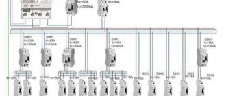
Scheme for connecting RCDs and automatic machines to the electricity meter
Let's turn to the question, like a machine gun, while implementing multi-level protection.
If a protected shutdown device is installed for individual areas, then we will talk about multi-level protection of a house or apartment. Typically, this diagram is for homes where grounding is present. In terms of price category, this option exceeds previous marks, and the devices are large in size. However, this system has such a significant advantage as the presence of autonomy for each individual household appliance. In the event of a short circuit in one of the devices, the entire living area will not be de-energized, but only the one in which there is a current leak from the network will cease to function. Here the connection to the electrical network changes; now there are as many cables coming out of the reading device as there are protection devices.
Today, RCDs and differential relays are often used, the connection diagram of which differs in that there is an absence of an automatic device. The general principle of connecting a system with a differential device is similar to the previous one, but the installation of additional current protection is provided.
How to connect an RCD?
Connecting the RCD can be done in several ways depending on the wiring diagram. We will analyze the most popular installation and connection schemes for RCDs and give some recommendations.
| Installation option | Description |
| Installation of one common RCD at the input | The device is installed after the input circuit breaker and meter, but before the group circuit breakers. This installation option is more economical. However, it has a significant drawback: if there is a current leak on a metal object or a false operation of the RCD itself due to a malfunction of its components, all consumers in the house will turn off. |
| Installation of a general RCD at the input and at each individual group | In this case, the RCD is placed after the meter. Next, on each group line after the circuit breaker, additional devices are installed whose breaking current value will be in a lower range depending on the type of load and room. In this case, when a leakage current occurs, only one group will turn off, and it is easier and faster to find the location of the fault. Although this option is expensive, since it requires the purchase and installation of a large number of RCD modules and a spacious switchboard, it is more justified from the point of view of ensuring the safety and functionality of the electrical system. Note! For each powerful electrical appliance (cooker, oven or boiler), it is recommended to create an individual line with protective automation: a circuit breaker and an RCD. It is also recommended to connect the RCD separately to each zone of the house (kitchen, bathroom, garage, living rooms) or to a group of loads of the same intended purpose. |
The installation sequence of the circuit breaker and the RCD does not matter: the connected device before or after the machine will equally protect the electrical circuit from current leakage. However, in practice, the RCD for each line is often located after the machine, but this is primarily due to ease of installation.
Note!
Some users, instead of an RCD and a circuit breaker, install a differential circuit breaker both to protect the entire electrical system and each line. However, the separate RCD+AV system has a significant advantage: if one of the devices fails, replacing it will be much cheaper.
When connecting the input phase and neutral wires to the RCD, it is necessary to use the upper terminals of the device, observing the polarity. The lower connectors are intended for output to consumers. If you connect them incorrectly, false alarms will occur in the device. In this case, the zero outputs of each installed RCD cannot be connected into one conductor. For a three-phase RCD, similar rules apply as for the installation of single-phase models (an article on how to correctly install a distribution board and place all modular components in it).
After installation, you need to check the RCD for serviceability. To do this, you can use its internal functionality. On the body of the product there is a button with the letter “T”, when pressed, the RCD will test the operation, that is, it will simulate the conditions of current leakage on the line. If the device turns off, then it is operational and ready for use.
Connection diagrams for RCD with switch
Protective equipment must be connected using two cables. The first will carry the load current, the second will be directed to the external circuit from the consumers. In order not to think about installing an RCD before or after the machine, you should use popular schemes.
For several groups of difavtomats - one RCD
Clause 7.1.79 of the PUE allows for the protection of several lines using an RCD. The device needs to be placed on top, then the switches on the consumer groups. In case of short circuits, the current passes through the RCD to the group circuit breaker, then to the power cable and to the consumer. If the rating of the devices is selected correctly, none of them will be damaged.
The advantages of implementing the scheme include saving money and space in the distribution panel. The downside of the connection is that all groups are disconnected after the RCD is triggered.
Installation of RCD to the machine
RCD in front of the machine
The diagram provides for installation in the following sequence:
- Safety shutdown device.
- Difavtomat.
- Power cord.
- Consumer.
If there is damage, the short circuit current passes through the RCD until the circuit breaker stops.
RCD after the machine
RCD after the machine
The system is assembled according to the principle;
- switch - two-pole or feeder;
- counter;
- RCD;
- machines depending on the number of lines.
This option is correct, since it is easy to understand how to turn off the machine and apply input to its terminals. Despite the fact that RCDs break more often, they are easier to replace.
At the moment of a short circuit, the current will pass from the switch to the RCD, then to the power wire, then to the consumer. The switch stops and the protective device remains intact.
Connecting an RCD to a group of machines
Connecting an RCD to a group of machines
A similar circuit is assembled in a three-phase switchboard, where there are:
- 3 three-phase difavtomat;
- three-phase RCD;
- 2 single-phase RCDs;
- 4 single-phase single-pole circuit breakers.
From the first input circuit breaker, the voltage will go to the second three-phase circuit through the upper terminals. From the same device, one phase will go to a single-phase RCD, the second to the next one.
Single-phase protection devices have two poles, difautomatic devices have one. In order for the system to work without failures, it is necessary not to connect the working zero after it. For this reason, a zero bus must be installed after each protective device.
If there are two-pole circuit breakers, a separate zero bus is not installed. When two zeros are combined, a false positive may occur.
The first single-pole RCD is connected to differential circuit breakers No. 1 and No. 3, the second - to No. 2 and No. 4. The load is applied to the lower terminals.
The grounding bus is common, but it must be installed separately. Three phases with a working zero are connected to the input device. It is connected to the common zero, and then diverted to all RCDs. After device No. 1 it goes to a three-phase load, after the remaining single-phase loads - to each bus.
In the apartment
Let's look at the case when the installation of protection equipment takes place in an apartment panel. Some builders, when delivering houses with an open plan, rent out housing without wiring the internal electrical network. This is understandable; it is not known where the partitions and, accordingly, sockets and lighting will be located. Therefore, they only introduce cable into the apartment.
On the floor electrical panel there is an introductory circuit breaker and an electric meter. The future owner enters into a contract with another contractor for internal electrical work. The wiring diagram will vary depending on customer requirements. It will depend on the circuit and the loads which RCD to install. If desired, any man can do this work on his own.
We will assume that the wiring in the apartment corresponds to the protection installation diagram presented in the previous figure. The input machine and counter are located in the floor panel, and all other elements will be located in the apartment box. To do this, you need to install an electrical panel in the corridor, next to the cable entry point. The sequence of work during installation is as follows:
- the input machine is turned off. A sign “Do not turn on, people are working” is posted;
- An outlet is connected to the cable that was brought into the apartment. It will be needed to connect working tools and lighting;
- the plate is removed, the machine is turned on;
- holes are drilled in the wall using a hammer drill for fastening the box. Dowels are inserted and the shield is attached to the wall with screws;
- after this, a metal strip is inserted and secured to the inner wall of the box with screws.
There shouldn’t be any difficulties if you perform all the steps consistently and carefully.
Connection recommendations
Before connecting the ouzo to the power supply line along with distribution (linear) machines, the user should be reminded of a number of requirements for devices of this class by current regulations.
In general, they come down to instructions according to which the sequence and order of actions when installing an RCD are established
When considering these requirements, it is recommended to pay special attention to the following important points:
- In private houses with power equipment connected to a 380 Volt network, the installation of a three-phase protection device is required;
- To connect a three-phase ouzo, wires of the appropriate cross-section in insulation of different colors must be used;
Note! The color of insulating coatings is selected according to generally accepted standards. A visual representation of the choice of wire colors can be obtained in the figure below;
A visual representation of the choice of wire colors can be obtained in the figure below;
Wire colors by phase
To design the common (ground) terminal of a three-phase circuit, as a rule, a wire in blue insulation is used.
Taking into account all the above conditions, the connection procedure in this case can be represented by a list of recommendations and advice coming from specialists. Below are just a few of them:
- Protective devices are placed in their designated places only after the power line of the apartment or house is completely de-energized;
- Before connecting ouzo and automatic machines into a single electrical circuit, try to decide on the place intended for their installation on the instrument panel;
- It is recommended to choose it as close as possible to the electric meter installed on the input panel;
- The so-called “individual” RCDs, designed to protect a single supply line (bathroom, for example), must be used strictly for their intended purpose. They are not allowed to be installed after the meter as a general protective device for the apartment.
In the final part of the review, which covers the questions: why is an RCD needed, and how should it be connected to already installed equipment, we note the following.
When answering the question whether ouzo should be placed immediately after the counter, there is always a consonant statement. In this article you can also find out which ouzo to choose if the apartment has a given number of machines. We hope that after reading all the material presented, users will be able to independently understand the issues of installing protective devices in power circuits.
Selection of RCD by parameters
After the RCD connection diagram is ready, it is necessary to determine the parameters of the RCD. As you know, it will not save the network from overloads. And from a short circuit too. These parameters are monitored by the circuit breaker. To ensure the safety of all wiring, an input machine is installed at the entrance. After it there is a meter, and then they usually install a fire protection RCD. It is chosen specifically. The leakage current is 100 mA or 300 mA, and the rating is the same as that of the input circuit breaker or one step higher. That is, if the input circuit breaker is set at 50 A, the RCD after the meter is installed at either 50 A or 63 A.
The fire protection RCD is selected according to the rating of the input circuit breaker
Why a step higher? Because automatic protective switches operate with a delay. They can carry a current that exceeds the rated current by no more than 25% for at least an hour. The RCD is not designed for prolonged exposure to high currents, and is likely to burn out. The house will be left without electricity. But this applies to determining the rating of a fire protection RCD. Others are chosen differently.
Rated current
How to choose the RCD rating? It is selected according to the method for determining the rating of the machine - depending on the cross-section of the wire on which the device is installed. The rated current of the protective device cannot be greater than the maximum permissible current for a given wire. To make selection easier, there are special tables, one of them is below.
Table for selecting the rating of the circuit breaker and RCD
In the leftmost column we find the wire cross-section; to the right there is the recommended rating of the circuit breaker. The RCD should have the same. So choosing the rating of the leakage current protective device is not difficult.
Trip current value
When determining this parameter, you will also need an RCD connection diagram. The rated breaking current of the RCD is the value of the leakage current at which the power is turned off on the protected line. This parameter can be 6mA, 10mA, 30mA, 100mA, 500mA. The lowest current - 6 mA - is used in the USA, in European countries, and we don’t even have them for sale. Devices with a maximum leakage current of 100 mA or higher are used as fire protection. They are standing in front of the entrance machine.
For all other RCDs, this parameter is selected according to simple rules:
- Protection devices with a rated shutdown current of 10 mA are installed on lines that go into rooms with high humidity. In a house or apartment, this is the bathroom; there may also be lighting or sockets in the bathhouse, swimming pool, etc. The same shutdown current is set if the line powers one electrical appliance. For example, a washing machine, electric stove, etc. But if there are sockets on the same line, more leakage current is needed.
- An RCD with a leakage current of 30 mA is placed on group power lines. When more than one device is connected.
This is a simple algorithm based on experience. There is another method that takes into account not only the number of consumers, but also the rated current in the protection zone, or rather, the cross-section of the wire, since the rated current of the power supply line depends on this parameter. This is more correct, since it explains how to select the value of the leakage current for a general RCD, for example, and not just for devices that are installed on consumers.
Table for selecting the rated shutdown current for RCDs
It is also necessary to take into account the individual leakage currents of each device. The fact is that on every more or less complex device some small current “leaks away”. Responsible manufacturers indicate it in the specifications. Let’s say there is only one device on the line, but its own leakage current is more than 10 mA, install an RCD with a leakage current of 30 mA.
Monitored leakage current type and selectivity
Different instruments and devices use current of different forms, accordingly, the RCD must control leakage currents of different types.
- AC — alternating current (sinusoidal shape) is monitored;
- A - variable + pulsating (pulses);
- B - constant, pulsed, smoothed variable, variable;
- Selectivity. S and G - with a shutdown time delay (to exclude accidental operations), the G-type has a shorter shutter speed.
Selecting the type of leakage current to be monitored
The RCD is selected depending on the type of load being protected. If digital equipment is connected to the line, either type A is required. The lighting on the line is AC. Type B is, of course, good, but too expensive. It is usually installed in areas with increased danger in production, and very rarely in the private sector or in apartments.
RCDs of class G and S are installed in complex circuits if there are RCDs of several levels. This class is chosen for the “highest” level, then when one of the “lower” ones is triggered, the input protective device will not turn off the power.
How to calculate the leakage current in the group line of an RCD (difavtomat)?
In this article I want to touch on, on the one hand, a very simple topic, and on the other hand, a very controversial one. Let's talk about existing technical regulations, the work of RCDs, experience in design and approval of project documentation. The occasion was a recent webinar on RCDs.
I try, whenever possible, to attend all webinars where I can improve my professional skills. By far the best webinars are from IEK. It is not always possible to attend them for one reason or another. I didn’t watch the entire webinar about RCDs, I had to go to the Ministry of Emergency Situations to take down comments, but that’s another topic...
As the webinar showed, not everyone understands the subtleties and problems that may arise when calculating leakage currents.
This topic has been raised more than once on the blog and forum, but, nevertheless, I would like to collect all the thoughts in one article.
At the webinar I asked a very simple question: how to calculate the leakage current with a design current of 25 A and a cable length of 1 m?
By the way, I often ask questions to which I have not very clear answers.
Of course, they immediately poked my nose into PUE 7:
7.1.83. The total leakage current of the network, taking into account the connected stationary and portable electrical receivers in normal operation, should not exceed 1/3 of the rated current of the RCD. In the absence of data, the leakage current of electrical receivers should be taken at the rate of 0.4 mA per 1 A of load current, and the network leakage current at the rate of 10 μA per 1 m of phase conductor length.
I had to count everything myself, because... everyone decided that this answered my question
Before counting, let's think about the first sentence of clause 7.1.83, and its essence is as follows:
I calculated leakage < 1/3 I cal.
That is, if the RCD is 30mA, then the calculated leakage current should not exceed 10mA. Surely you are thinking, why 10 mA if the RCD is 30 mA? But the whole point is that the RCD is triggered at a leakage current of 0.5In.ut. An RCD with a leakage current of 30 mA will operate at a leakage current of 15 mA.
RCD tripping
Now let's calculate the leakage current.
The fact is that the PUE offers a calculation formula in the absence of data. Can anyone tell me where to get the data at the design stage? It is necessary to perform the calculation according to the proposed methodology.
25*0.4+1*0.01=10.01mA > 10 mA
It follows from this that the calculation according to the PUE will not allow us to use an RCD with a rated current of more than 25 A and a leakage current of 30 mA.
I would like to remind you that 30 mA is a safe current for the human body. 100 mA is no longer completely safe.
What if you have a current of 30-40 A? In this case, I have more than once installed an RCD with a leakage current of 100 mA, because... Our energy inspection requires a leakage current value for each RCD. How can you calculate differently at the design stage?
It turns out that we have to underestimate security. I very much doubt that there will really be such leakage currents in the circuit, but there will be no false alarms. If there was a device for measuring leakage currents, we could experiment.
I’m wondering if the developers of TKP 339-2011, TKP 45-4.04-149-2009 thought about it when they copied the PUE?
8.7.14 The rated residual current of the RCD must be at least three times greater than the total leakage current of the protected network, taking into account the connected stationary and portable power receivers in normal operation. For electrical receivers with a rated current exceeding 32 A, in the absence of data on the leakage current of electrical receivers, its value should be taken at the rate of 0.4 mA per 1 A of load current, and the value of the network leakage current at the rate of 10 μA per 1 m of phase conductor length.
But what about RCDs with rated currents less than 32 A?
I can only make my assumption: the leakage current for an RCD with a rated current of no more than 25 A can not be considered. Perhaps this is what the developers of these documents had in mind.
Regulatory documents generally indicate 30 mA for sockets or are simply recommended. It turns out that if we connect some powerful stove in the kitchen through a 100 mA RCD, we don’t even break anything.
Links to TNLA:
TKP 45-4.04-149-2009: Installing an RCD with an operating current of up to 30 mA is considered an additional measure of protection against direct contact in the event of insufficiency or failure of the main types of protection.
D.17 For group lines of electrical receivers specified in D.3 and D.4, the rated differential disconnecting current should be taken up to 30 mA.
In group lines that supply socket networks of individual electrical receivers with natural leakage currents of 10 mA or more (for example, electric stoves), it is allowed to accept an RCD with a rated differential tripping current of up to 100 mA and an operating time of no more than 100 ms.
TKP 339-2011:
8.7.4 On group lines supplying plug sockets for portable electrical appliances, it is recommended to provide protective shutdown devices with a rated differential operating current of no more than 30 mA.
8.7.17 For residential buildings, if the requirements of 8.7.17 are met, the functions of the RCD according to 8.7.17 and 8.7.19 can be performed by one device with a response current of no more than 30 mA.
PUE 7:
7.1.82. It is mandatory to install an RCD with a rated response current of no more than 30 mA for group lines supplying electrical outlets located outdoors and in particularly dangerous and high-risk areas, for example in zone 3 of bathrooms and shower rooms in apartments and hotel rooms.
Manufacturers of electrical products have a range of RCDs (difavtomat) for 63 A with a leakage current of 30 mA. How to apply such an RCD? Or does anyone know the real values of leakage currents?
I recommend reading:
Symbols of switches and sockets
Emergency lamp control circuit
Apartment power supply
Main design features of 10kV overhead lines
Connection diagrams for RCDs in a single-phase network
Most household consumers are powered by a single-phase circuit, where one phase and neutral conductor is used to supply them with electricity.
Depending on the individual characteristics of the network, single-phase power supply can be provided according to the following scheme:
- with a solidly grounded neutral (TT), in which the fourth wire acts as a return line and is additionally grounded;
- with combined neutral and protective conductor (TN-C);
- with separated zero and protective grounding (TN-S or TN-CS; when connecting devices indoors, you will not find any difference between these systems).
It should be noted that in the TN-C system, in accordance with the requirements of clause 1.7.80 of the PUE, the use of differential circuit breakers is not allowed, except for the protection of individual devices with the obligatory combination of zero and ground from the device to the RCD. In any situation, when connecting an RCD, the characteristics of the supply network should be taken into account.
Without grounding
Since not all consumers can boast of having a third wire in their wiring, residents of such premises have to make do with what they have. The simplest circuit for connecting an RCD is to install a protective element after the input circuit breaker and the electric meter. After the RCD, it is important to connect circuit breakers for different loads with the corresponding shutdown current. Please note that the operating principle of RCDs does not provide for disconnecting current overloads and short circuits, so they must be installed together with circuit breakers.
Rice. 1: Connecting an RCD in a single-phase two-wire system
This option is relevant for apartments with a small number of connected devices. Since if there is a short circuit in any of them, shutting down will not bring any noticeable inconvenience, and finding the damage will not take much time.
But, in cases where a sufficiently branched power supply circuit is used, several RCDs with different operating current values can be used.
Rice. 2: connecting an RCD in a branched single-phase two-wire system
In this connection option, several protective elements are installed, which are selected according to the rated current and operation current. As general protection, an incoming 300 mA fire protection RCD is connected here, followed by a neutral and phase cable to the next 30 mA device, one for sockets, and the second for lighting; a pair of 10 mA units are installed for the bathroom and nursery. The lower the response rating is used, the more sensitive the protection will be - such RCDs will operate at a significantly lower leakage current, which is especially important for two-wire circuits. However, it is also not worth installing sensitive automation on all elements, since it has a high percentage of false positives.
With grounding
If there is a grounding conductor in a single-phase system, the use of an RCD is more appropriate. In such a scheme, connecting the protective wire to the device body creates a path for current leakage if the insulation of the wires is broken. Therefore, the protection will operate immediately in the event of damage, and not in the event of electric shock to a person.
Rice. 3: Connecting an RCD in a single-phase three-wire system
Look at the figure; the connection in a three-wire system is made in the same way as a two-wire system, since only a neutral and phase conductor are required for the device to operate. The grounding device is connected only to the protected objects through a separate grounding bus. Zero can also be connected to a common zero bus; from the zero contacts it is routed by wires to the corresponding devices connected to the network.
As in a two-wire single-phase circuit, with a large number of consumers (air conditioner, washing machine, computer, refrigerator and other amenities of civilization), an extremely unpleasant option is the freezing of all of the above electronic circuits with loss of data or disruption of their functionality. Therefore, several RCDs can be installed for individual devices or entire groups. Of course, connecting them will result in additional costs, but will make finding damage a more convenient procedure.
Rules for installing RCD - residual current device
The rules are formulated according to their significance and mandatory implementation. The list is ranked from required to recommended.
1. When installing, follow the safety precautions of an electrician in the apartment;
2. An RCD is installed in the floor or apartment electrical panel;
3. RCDs without built-in protection must be installed together with circuit breakers (circuit breakers). Automatic switches will protect the RCD from burnout during overload and short circuit;
4. The RCD is not installed on a wiring group without a circuit breaker. The tripping current of the circuit breaker must be no more than the rated current of the RCD. For example, a 40 Ampere RCD must be protected by a 36 Ampere circuit breaker, or in extreme cases, 40 Ampere;
5. The circuit breaker in a circuit with an RCD can be either single-pole (per phase) or two-pole (phase + zero) and it must be installed before the RCD on the power supply side;
Explanations for the diagram: RCD 3 is protected by circuit breaker 1 and is installed for three groups with circuit breakers 4, 5, 6.
6. You can install one RCD on several group circuits of an apartment, provided that each of the groups is protected by a separate circuit breaker;
Related articles: Choosing a circuit breaker
7. If you plan to install several RCDs, then for each RCD, at the output, you need to install its own zero bus, separate from the others;