Operating principle of an RGB lamp
To approach the issue of connection competently, you need to understand how this lighting device works and how to control it. The tape consists of individual sections into which it can be cut at specified locations.
Diagram of one element of the RGB canvas.
Each segment contains three groups of LEDs - red, blue and green. They are assembled sequentially by color and connected in parallel according to a circuit with a common anode. Each color chain has its own current-limiting resistor. Positive tension is always present. The LEDs are lit by connecting the cathode to the common wire. By separately adjusting the brightness of each LED, you can achieve almost any color, with the exception of natural white.
To obtain a white glow close to natural, one white LED is added to each element of the tape. Such a device is designated by the letters RGBW.
What is needed to connect the lamp
To connect an RGB LED strip to a circuit, you will need the following blocks:
- the lighting fixture itself is of the required length;
- power supply (possibly several);
- RGB controller;
- amplifier (several);
- connecting wires;
- power switch;
- connectors (but it’s better to master soldering).
RGB connector for direct connection.
This list is complete; some elements may be missing from a specific design.
Tools you will need:
- wire cutters for cutting wires to the required length;
- a lineman's knife for stripping ends (or better yet, a special insulation stripper;
- soldering iron with consumables (for real craftsmen).
Soldering kit.
You will also need fastening elements, but they are selected according to location.
Installation of LED strip. Connection diagram for tape, power supply, RGB controller and amplifier
How to connect an LED strip. Connection diagram and installation of LED strip.
Installation of the LED strip must begin with preparing the base on which it will be glued. First of all, the bases need to be degreased and cleaned of dust and dirt. LED strips can be glued at any angle, but we still recommend avoiding sharp corners.
Installation of LED strips is very simple, but you must adhere to several rules and instructions.
All segments of the LED strip are connected in parallel to each other, and the entire total current passes through tracks that are designed for a certain power and number of LEDs, since the strip is produced in 5-meter lengths, and the conductive tracks are designed for this length. From what has been written, we can draw a conclusion, not even a conclusion, but a very important rule and condition, when assembling a backlight connection diagram: “You cannot connect more than 5 meters of tape in series.” In other words, you cannot connect the beginning of another to the end of a 5-meter spool, and so on (see figure below).
If you have the task of connecting a tape of more than 5 meters, you need to connect the sections in parallel; to do this, you need to stretch long connecting wires parallel to the tape. Thus, the current flows along the connecting wire to the second tape, and not along the tracks of the first.
Also, you need to take into account that a long wire has a high resistance; we recommend using a double-section wire (2x1.5).
There is a second connection option, here the power supply is located in the middle of two pieces of tape. With this arrangement, the length of the connecting wire will be much shorter, and its cross-section, in comparison with the previous diagram, will be used less - 2x0.75 (see diagram below).
If the power of one transformer is not enough, you can use a connection scheme with several power supplies. This scheme is recommended if one block for the entire lighting is too large (due to high power) and does not fit into an already prepared place for it (for example, a niche in a plasterboard ceiling). With this scheme, each power supply will be smaller and can be easily hidden. It is worth remembering that when implementing this scheme, its cost will increase, since two power supplies are more expensive than one of the same power.
Connection diagram for RGB LED strip (multicolor).
The connection diagram for an RGB LED strip and a monochrome (one-color) LED strip are almost the same, the only difference will be the use of an RGB controller when connecting a multicolor RGB LED strip. The controller will be located between the power supply and the LED strip.
If a situation arises that you need to connect more than 5 meters of RGB LED strip, then you need to use a parallel connection circuit using a connecting wire, similar to the monochrome strip circuit that was described earlier.
The only disadvantage of the above mentioned schemes is the high power, the dimensions of the power supply and the extra costs for connecting wires. These two schemes are more suitable for one or two 5-meter sections, but if you use three or four 5-meter sections (total length of the strip 15-20m), the RGB controller will be overloaded, since the RGB LED strip has quite a lot of power (three color channels and three LED crystals). The total currents of all tape segments will pass through the controller. In this case, we recommend using a circuit with several power supplies, and in order to force the LED strip connected to different RGB controllers to synchronously execute commands from the control panel, you need to add an RGB amplifier to the circuit, or several amplifiers if there are more than two power supplies.
Why do this? There is only one answer: if you do not use an RGB amplifier, each piece of tape will live its own life and carry out commands only from its control panel.
Below we suggest looking at an example of a diagram for connecting more than 5 meters of RGB LED strip using several power supplies, one RGB controller and several RGB amplifiers.
ledworld.ua
Which controller to choose
A controller is needed to control the colors of the LED strip. It allows you to set the required proportions of red, green and blue colors and get almost any color, including conventional white. You can also control the dynamics of the transition from one color to another. Regulation is carried out using the PWM method, so power losses when changing brightness are small. Based on their consumer properties, most color dimmers can be divided into categories:
- With remote control. The mode is selected from the control panel (similar to a television or other household equipment). Communication between the remote control and the controller can be via an IR channel or a radio channel (such units have an RF label). In the first case, during installation it is necessary to ensure direct visibility between the transmitting and receiving parts. In the second there are no such restrictions. You can control the glow even in the next room or hide the receiving and operating parts behind interior elements.
RF controller for 12/24 V and current up to 18 A. - Built into socket boxes or furniture elements. This controller looks like a futuristic light switch. You can set operating modes in the same way as with the remote control.
Built-in control unit. - Controller controlled from a personal computer. The possibilities for creating lighting effects are unlimited. But you need a PC on hand.
The choice of control unit based on electrical parameters is made according to two main characteristics:
- operating voltage - must match the voltage of the tape and power supply;
- highest power - must correspond to the total power of the tape that is planned to be connected.
If you need to adjust the brightness of a very long (and therefore very powerful) lamp that no industrial controller can handle, you will need an amplifier.
Is it possible to do without a controller?
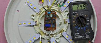
The controller is not a fundamental element, without which the RGB lamp will not work. Connecting an RGB strip can be done without it by turning on all elements of the lamp constantly at full brightness.
Connecting the LED lamp to maximum brightness.
In this embodiment, the lamp will emit light close to white. From an economic point of view, this makes no sense - a tape with a white emission color is much cheaper . Another option is to connect a colored tape for separate manual adjustment of the channels. This can be done using potentiometers or another method.
Connecting an LED lamp for manual adjustment.
In this option, the brightness of the channels can be adjusted separately, setting the desired color of the glow, but some of the power is uselessly lost on variable resistors. Instead of potentiometers, you can install separate switches and mix colors at full brightness.
You can look for other ways to regulate the current manually, but all these methods only provide a static picture. Dynamic lighting effects are only possible with the help of an RGB controller.
You can also connect a monochrome lamp with the appropriate voltage and power to the controller. It is connected to one of the outputs of the control unit and operates in brightness control mode.
Popular connection schemes
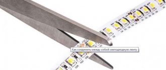
Having analyzed many options for connecting rgb strips, we have identified a number of the most popular schemes. To implement any of the connection diagrams in practice, you will need knowledge of how to properly cut an LED strip.
Standard connection diagram
The procedure for installing the circuit consists of the following sequential steps:
- The controller is connected to the low-voltage connectors of the power supply.
- As a rule, the “+” connectors are connected with a red wire, and the “–” connectors with a black wire.
- An LED strip is connected to the controller, which has 4 outputs: three of them are for controlling red, green and blue colors, and the fourth wire is for general power supply of the device.
Standard RGB controller connection diagram
Option for connecting two LED strips
The features of this connection option include the following important points:
- To connect, you need two power supplies and an RGB amplifier.
- The circuit is simple, however, during installation you need to carefully ensure that the wires are connected according to the color coding.
- The connection option is also acceptable for a 10 meter long LED strip.
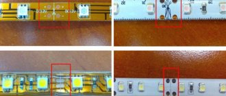
When connecting several LED strips, you should not make the mistake shown in the photo:
This is due to the fact that a low power voltage will reach the LEDs located at the far end, as a result the multi-color tape will glow unevenly.
In other words, if the circuit provides for the connection of several LED strips, then they should only be connected in parallel.
Connecting an RGB tape 20 meters long
This connection uses two power supplies. However, if the power of one unit is enough, then all the elements can be connected according to the following scheme: controller-amplifier-power supply.
When you can't do without an amplifier
If the power capabilities of the controller are exhausted, and it is necessary to increase the length of the lamp blade, you can use an amplifier - in foreign terminology, an “RGB signal repeater”. And in fact, in terms of voltage, it repeats the signal applied to the input, but amplifies it in terms of current. An amplifier is selected based on several parameters:
- the voltage must correspond to the voltage of the controller (respectively, the voltage of the power supply and the lamp);
- the power must sufficiently ensure the energy supply of the intended section of the belt;
- number of channels - at least three for an RGB lamp;
- execution - in most cases with a common anode, but it doesn’t hurt to check.
You can also pay attention to other parameters - operating temperature range, degree of protection, etc. For the most part, this is necessary if you plan to install the repeater in difficult conditions (outdoors, etc.).
How to connect 10, 15, 20 or 30 meters of RGB LED strip? — Article about parallel connection
If you need to connect 5 meters of LED strip, then everything is simple: you just need to connect its + and - contacts with the corresponding contacts from the power supply and voila! Your feed is working.
What to do if you have, for example, 30 meters of 12v tape? At first glance, everything is the same: connect the entire tape in a line and connect it to the power supply. However, in practice, if you do this, you will get something like this: the first 5 meters will shine as it should, and then the brightness of the tape will decrease exponentially: the further you go, the dimmer. Moreover, this will not depend on the power of the power supplies.
The voltage drop is to blame. To understand, let's turn to Ohm's law, which relates voltage loss per meter ΔU, current strength l and resistance per meter R:
ΔU=IR
Where:
- R - wire resistance (in ohms Ohm/m)
- I - current strength (in amperes A)
- ΔU - voltage drop (in volts V/m)
The formula shows that the voltage drop directly depends on the current and line resistance: The greater either of these two variables, the more voltage we lose.
Let's return to the example: we still have 30 meters of dimly luminous tape connected in a line. What went wrong?
Operating multiple reels of tape requires more current than operating one. By increasing the current, we increased the voltage drop ΔU.
We increased the line length, which led to an increase in the overall resistance. If earlier the total resistance of the line was equal to 5m * R, now it is equal to 30m * R. Since we increased the resistance, the voltage drop also increased!
And how to connect more tape?
- We need to reduce the current.
In practice, it looks like this: each coil of 12v tape needs to be connected in parallel. To do this, you need to run not just one two-wire wire from the power supply, but several - for each coil separately. Then everything is as usual: you connect the ribbon, observing the polarity, and it shines equally bright along its entire length.
— It is necessary, if possible, to reduce the length of the line.
In our case, this can be done by installing power supplies in the middle of the chain, and not at the very beginning. This way you can reduce the maximum wire length.
Wrong:
More correct:
Let's say we figured out how to connect several tens of meters of single-color tape:
1) Connect in parallel every 5 meters to the power supply.
2) Minimize the line length.
But what about RGB tape? Its connection is somewhat more complicated, because for normal operation the RGB strip requires not only a power supply, but also a controller. It converts the incoming voltage, sending a signal to the tape through 4 channels: R, G, B, and +. Those. first we connect the power supplies to the controller, from which, then, the power goes to the tape in the form of an RGB signal. Then there are 2 options:
The controller has enough power.
If you need to connect 20-25 meters of 14.4W RGB strips, then the power of one 432W controller is quite enough. In this case, you can simply connect the entire RGB strip to the controller in the same way as we would connect a single-color strip to the power supply: every 5 meters we power it in parallel directly from the RGB controller.
The total power of the tape is greater than the power of the controller. If you need to connect, for example, 100 meters of RGB tape, then one controller will not be enough. What should I do? Use amplifiers as in the photo below:
What are amplifiers?
The amplifier, as the name suggests, is designed to amplify the RGB signal. Pay attention to the photo above. What to connect where:
Input - incoming signal R, G, B and + from the controller. Those. Instead of running the signal from the controller to the tape, we route it to the amplifier.
Output - outgoing signal R, G, B and +, we connect the wires from the tape to these terminals. They will send an amplified signal.
Power - incoming voltage 12v. This is where we bring the wires from the power supply.
But in practice?
In reality, this means that you can connect as many RGB strips as you like and control them from one remote control.
To do this:
Cheaper option:
We connect power supplies of appropriate power to the RGB controller and to the amplifiers.
From the controller we conduct the outgoing signal to amplifiers and to a section of tape corresponding in power to the controller.
From the amplifiers we direct the wires to the rest of the tape. We connect the tape in parallel: every five meters directly to the amplifier.
Better option:
We connect power supplies to the controller and amplifiers.
From the controller we send the outgoing signal only to amplifiers.
And from the amplifiers we direct the wires to the tape.
With this approach, the controller will only be responsible for signal transmission, and the load will mainly fall on the amplifiers. In addition, the tape will shine equally throughout the entire area without loss of color and glow strength.
Dmitry Semenov
giant4.ru
Connection options for colored tape
The connection diagram option is determined only by the total power consumption of the LED strip, which depends on:
- specific consumption of one meter of canvas;
- total footage of the lamp.
The more the lamp consumes, the more complex the circuit.
Important! Scheme options are given depending on the footage of the tape, but the actual consumption must be clarified each time according to the technical characteristics of a particular RGB lamp.
Standard scheme
Using this diagram, you can connect the lamp if the total length of the canvas or the sum of its segments is no more than 5 meters.
Connecting short sections of LED strip.
The only task is to select the power source and control unit of the required voltage and power. Usually this is not difficult.
Power supply circuit for extended RGB strip
If the length of the canvas is more than 5 meters, then the sections cannot be connected in series. Too much current will flow through the conductors of the lamp, and they are not designed for it. Therefore, it is necessary to connect pieces of tape no more than 5 meters long in parallel; the connection should be made using connectors, or better yet, by soldering pieces of wire.
Connecting long sections of LED strip.
In this case, choosing a power supply and a controller for the required power is also not difficult.
Connection diagram for long blades
If the total length of the web segments does not allow you to select a suitable controller for power (or even a power supply for the appropriate current), then to expand the system you will have to use RGB signal amplifiers (one or more). For example, you need to connect a line 20 m or more long. All tapes are divided into groups so that the power of each group does not exceed the capabilities of the controller and amplifier.
Connecting sections of LED strip using amplifiers.
In theory, the system can be expanded indefinitely. If the voltage source alone is capable of providing power to all components of the circuit and everything is located close enough to avoid inconvenience when laying the power cable, then additional power supplies will not be needed.
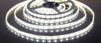
RGB LED strip
Introduction
LED RGB strip is a flexible strip with conductors and RGB LEDs (full color) printed on it.
Recently, LED strips have become widespread in architecture, auto and motorcycle tuning, costumes, decorations, etc. There are also waterproof tapes that can be used, for example, in swimming pools. LED strips come in two types: analog and digital . In analog strips, all LEDs are connected in parallel. Therefore, you can set the color of the entire LED strip, but you cannot set a specific color for a specific LED. These tapes are easy to connect and not expensive. Digital LED strips are a little more complicated. An additional microcircuit is installed for each LED, which makes it possible to control any LED. Such tapes are much more expensive than regular ones.
In this article we will consider working only with analog LED strips.
Analog RGB LED strips
Technical specifications: - 10.5mm width, 3mm thickness, 100mm length of one segment - waterproof - 3M tape on the bottom - max. current consumption (12V, white color) - 60mA per segment - glow color (wavelength, nm): 630nm/530nm/475nm
RGB LED strip circuit diagram
The tape is supplied in rolls and consists of sections 10 cm long. Each section houses 3 RGB LEDs, size 5050. Each section turns out to contain 9 LEDs: 3 red, 3 green and 3 blue. Section boundaries are marked and contain copper pads. Therefore, if necessary, the tape can be cut and easily soldered. LED strip diagram:
Energy consumption
In each section of the tape, 3 LEDs are connected in series, so 5V power is not suitable. The power supply should be 12V, but you can also supply 9V, but then the LEDs will not burn so brightly.
One segment LED line consumes approximately 20mA when supplied at 12V. That. if you turn on the white color (i.e. red 100%, green 100% and blue 100%), then the power consumption of the section will be about 60mA.
Now, you can easily calculate the current consumption of the entire tape. So, the length of the tape is 1 meter. The tape has 10 sections (10 cm each). The tape consumption with white color will be 60mA*10=600mA or 0.6A. If you use a PWM fade effect between colors, the power consumption can be halved.
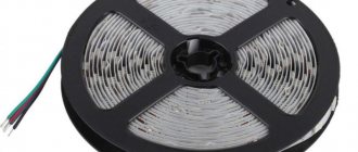
Connecting the tape
In order to connect the tape, you need to solder the wires to the 4 contact pads. We used a white wire for +12V, and the rest of the colors according to the colors of the LEDs.
Cut off the protective film at the end of the tape. From which side the connection will be made is not important, because symmetrical tape.
Strip the insulation layer to expose the contact pads.
Tin them.
Solder four wires. It is better to use multi-core wire (for example PV3 or PVS cable), it is more flexible.
To protect against water and external influences, you can use heat-shrink tubing. If the LED strip will be used in a humid environment, then additionally, the contacts can be coated with silicone.
Working with LED strip
The tape can easily be used with any microcontroller. To control LEDs, it is recommended to use pulse width modulation (PWM). Do not connect the tape pins directly to the MK pins, because This is a large current load and the controller may burn out. It's better to use transistors.
You can use NPN transistors or better yet N-channel mosfets. When selecting a transistor, do not forget that the maximum switching current of the transistor must be taken with a reserve.
Connecting LED strip to Arduino controller
Let's look at an example of connecting an LED strip to a popular Arduino controller. For connection, you can use inexpensive and popular mosfets STP16NF06. You can also use conventional bipolar transistors, for example TIP120. But compared to the mosfet, it has more voltage loss, so it is still recommended to use the former. The diagram below shows the connection of an RGB LED strip when using N-channel mosfets. The mosfet gate is connected to pin1 of the controller, the drain to pin2 and the source to pin3.
Below is a connection diagram when using conventional bipolar transistors (for example TIP120). The base of the transistor is connected to pin1 of the controller, the collector to pin2 and the emitter to pin3. A resistor with a resistance of 100-220 Ohms must be placed between the base and the controller output.
Connect a power source with a voltage of 9-12 Volts to the Arduino controller, and +12V from the LED strip must be connected to the Vin pin of the controller. You can use 2 separate power supplies, just do not forget to connect the “grounds” of the source and the controller.
Example program
To control the tape, the PWM output of the controller will be used, for this you can use the analogWrite() function for pins 3, 5, 6, 9, 10 or 11. With analogWrite(pin, 0) the LED will not light up, with analogWrite(pin, 127 ) the LED will burn at full intensity, and with analogWrite(pin, 255) the LED will burn at maximum brightness. Below is an example sketch for Arduino:
#define REDPIN 5 #define GREENPIN 6 #define BLUEPIN 3 #define FADESPEED 5 // the higher the number, the slower the fade effect will be void setup() { pinMode(REDPIN, OUTPUT); pinMode(GREENPIN, OUTPUT); pinMode(BLUEPIN, OUTPUT); } void loop() { int r, g, b; // fade from blue to purple for (r = 0; r 0; b—) { analogWrite(BLUEPIN, b); delay(FADESPEED); } // fade from red to yellow for (g = 0; g 0; r—) { analogWrite(REDPIN, r); delay(FADESPEED); } // fade from green to greenish blue for (b = 0; b 0; g—) { analogWrite(GREENPIN, g); delay(FADESPEED); } }
Original article
Tags:
- Translation
- RGB LED
How to avoid mistakes
The most common mistake even among experienced electricians trying to connect a control panel to an LED strip is exceeding the power capabilities of the power supply, controller or amplifier . This happens when the circuit is assembled “on the edge”, and it seems that the power supply will provide current, albeit without reserve. As a result, the service life of an expensive device turns out to be very short.
Another underestimation is the lack of wire cross-section. The powerful consumer is connected with wires that are too thin or too long. The first case leads to overheating, the second - to a voltage drop on the supply line and a dim glow of the lamp.
| Cross section of copper conductor, mm | 0,5 | 0,75 | 1 | 1,5 | 2 |
| Maximum permissible current with open installation, A | 11 | 15 | 17 | 23 | 26 |
You should also pay attention to the correct pinout of the RGB lamp. If you connect the wires not in accordance with the colors, you can get into trouble when different groups of LEDs light up on different sections of the fabric. This often happens when soldering is used to connect pieces of fabric.
At the end of the video: Instructions for connecting the LED strip to an infrared controller with a remote control.
Other errors may be the result of inattention and negligence during installation. Immediately after completion of work, it is necessary to check the correctness and reliability of the connections. If you do this before the first voltage is applied, the RGB lamp will last a long time.
Preparation
First of all, you need to purchase everything you need for work. It is worth remembering that the LED strip can be ordered from China, but in this case there will be no guarantee as such. If you buy it in a store, you will have to overpay, but if problems arise, you can return the product under warranty. You need the following:
- LED Strip Light. Choose a single-color or multi-color option depending on the purpose. Only products designed for 12 V voltage are suitable.
- Sharp knife. The easiest way is to use a stationery or construction one with replaceable blades. Scissors may also be needed.
- Side cutters, you can use wire cutters instead.
- Wires for connecting elements.
- Soldering iron, as well as solder and flux. You should select small options with a small tip; it is impossible to solder contacts with a standard device.
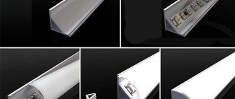
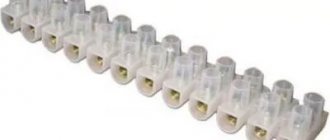
- Connectors, with their help it is not difficult to connect wires without soldering. Select according to the type of tape. For example, RGB has 4 pins, RGBW has 5, and RGBWW has 6.
Connectors for connecting LED strip.
For a multi-color option, you need to install a controller, with its help you can change the backlight shades. If you connect directly, either only one color will light up, or all of them at once.
To adjust not only the color, but also the brightness, you need to additionally purchase a dimmer.