Home > Electrician's Tips > Magnetic antennas made from coaxial cable
A magnetic loop home antenna is an excellent alternative to classic outdoor ones. Such designs allow transmitting signals up to 80 m. Coaxial cable is most often used for their manufacture.
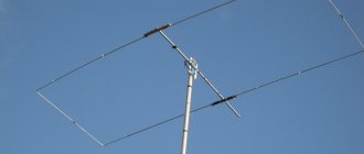
Classic version of a magnetic loop antenna
Frame magnetic installation is a subtype of small-sized amateur antennas that can be installed anywhere in a populated area. Under the same conditions, the frames show more stable results than their analogues.
In home practice, they use the most successful models from popular manufacturers. Most of the circuits are given in amateur literature for radio engineers.
Magnetic loop antenna made from coaxial cable indoors
DIY antenna assembly
Materials for production
The main element is a coaxial cable of several types, 12 m and 4 m long. To build a working model, you also need wooden planks, a 100 pF capacitor and a coaxial connector.
Assembly
A magnetic loop antenna is constructed without special training or knowledge of technical literature. By following the assembly order, you can get a working device the first time:
- connect wooden planks with a cross;
- cut grooves in the boards with a depth corresponding to the radius of the conductor;
- Drill holes on the slats at the base of the cross to secure the cable. Cut three grooves between them.
Precise sizing allows you to build a structure with high radio frequency reception.
Magnetic antenna made from coaxial cable
An interesting option for a small-sized loop antenna for amateur HF radio stations is the West German shortwave DF91V.
Small-sized frames - with a perimeter significantly smaller than the operating wavelength - are classified as so-called magnetic antennas, since when it comes to radio reception, they react to the magnetic component of an electromagnetic wave. This provides a number of advantages. Firstly, such an antenna does not require a good ground in the radio engineering sense of the word, i.e.
Its small size allows it to be used as a balcony or even indoor transmitting antenna. The quality factor of the frame is very high, several hundred, so when the operating frequency changes, it must be adjusted.
Search data for your request:
Schemes, reference books, datasheets: Discussions, articles, manuals:
Wait for the search to complete in all databases. Upon completion, a link will appear to access the found materials.
WATCH THE VIDEO ON THE TOPIC: Antenna on broadcasting all-audio.proon.
A magnetic loop home antenna is an excellent alternative to classic outdoor ones. Such designs allow transmitting signals up to 80 m. Coaxial cable is most often used for their manufacture. A frame magnetic installation is a subtype of small-sized amateur antennas that can be installed anywhere in a populated area.
Under the same conditions, the frames show more stable results than their analogues. In home practice, they use the most successful models from popular manufacturers. Most of the circuits are given in amateur literature for radio engineers. The main element is a coaxial cable of several types, 12 m and 4 m long. To build a working model, you also need wooden planks, a pF capacitor and a coaxial connector.
A magnetic loop antenna is constructed without special training or knowledge of technical literature. By following the assembly order, you can get a working device the first time:
A magnetic antenna made of coaxial cable is a loop of conductor that is connected to a capacitor. The loop usually looks like a circle. This is due to the fact that this shape increases the efficiency of the design.
The area of this figure is largest compared to the area of other geometric bodies, therefore, the signal coverage will be increased. Manufacturers of goods for radio amateurs produce round frames. There are also models in the form of triangles, squares and polygons. The use of such designs is determined in each specific case by various factors: the location of the device in the room, compactness, etc.
Round and square frames are considered single-turn, since the conductor is not twisted. Today, special programs like KI6GD allow you to calculate the characteristics of only single-turn antennas. This type has proven itself well for working in high-frequency ranges. Their main disadvantage is their large size. Many specialists strive to work at low frequencies, which is why the magnetic frame installation is so popular.
Comparative calculations of several circuits with one, two or more turns, under similar operating conditions, showed the questionable effectiveness of multi-turn designs. Increasing the turns as much as possible is advisable solely to reduce the dimensions of the entire device.
In addition, to implement this scheme, it is necessary to increase the cable consumption, therefore, the cost of homemade products increases unjustifiably. How to make a homemade antenna for a TV with your own hands?
For maximum efficiency of the installation, one condition must be achieved: the loss resistance in the frame web must be comparable to the value of the radiation resistance of the entire structure.
For thin copper tubes this condition is easily met. For large diameter coaxial cables, this effect is more difficult to achieve due to the high resistance of the material. In practice, both types of structures are used, since other types work much worse. If the device performs exclusively the function of a receiver, then conventional capacitors with solid dielectrics can be used for its operation. To reduce the size, the receiving frames are made of multi-turn thin wire.
Such designs are not suitable for transmitting devices, since the action of the transmitter will heat the installation. The braided magnetic frame provides greater efficiency than copper tubes and a thicker conductor diameter. Models with a black plastic shell are not suitable for home experiments, as they contain a large amount of soot.
During operation, metal parts, when the shell is heated, emit chemical compounds harmful to humans. In addition, this feature reduces the transmission signal. This type of coaxial cable is only suitable for large antennas, since their conductor radiation resistance completely compensates for the input resistance. Due to the physical properties of coaxial cables, antennas are not affected by temperature and precipitation.
Only the sheath created by external factors - rain, snow, ice - is susceptible to negative consequences, since water has large losses at high frequencies compared to the cable. As practice shows, such structures can be used on balconies for several decades. Even in severe frosts there is no significant deterioration in reception.
Shape of magnetic frames
Contactors and magnetic starters
A magnetic antenna made of coaxial cable is a loop of conductor that is connected to a capacitor. The loop usually looks like a circle. This is due to the fact that this shape increases the efficiency of the design. The area of this figure is largest compared to the area of other geometric bodies, therefore, the signal coverage will be increased. Manufacturers of goods for radio amateurs produce round frames.
Installation of the structure on the balcony
To ensure that devices operate on a specific wavelength range, loops of various diameters are constructed.
There are also models in the form of triangles, squares and polygons. The use of such designs is determined in each specific case by various factors: the location of the device in the room, compactness, etc.
Round and square frames are considered single-turn, because the conductor is not twisted. Today, special programs like KI6GD allow you to calculate the characteristics of only single-turn antennas. This type has proven itself well for working in high-frequency ranges. Their main disadvantage is their large size. Many specialists strive to work at low frequencies, which is why the magnetic frame installation is so popular.
Comparative calculations of several circuits with one, two or more turns, under similar operating conditions, showed the questionable effectiveness of multi-turn designs. Increasing the turns as much as possible is advisable solely to reduce the dimensions of the entire device. In addition, to implement this scheme, it is necessary to increase the cable consumption, therefore, the cost of homemade products increases unjustifiably.
How to make a homemade antenna for a TV with your own hands?
Magnetic frame canvas
For maximum efficiency of the installation, one condition must be achieved: the loss resistance in the frame web must be comparable to the value of the radiation resistance of the entire structure. For thin copper tubes this condition is easily met. For large-diameter coaxial cables, this effect is more difficult to achieve due to the high resistance of the material. In practice, both types of structures are used, because other types work much worse.
Receiving frames
If the device performs exclusively the function of a receiver, then conventional capacitors with solid dielectrics can be used for its operation. To reduce the size, the receiving frames are made of multi-turns (made of thin wire).
Such designs are not suitable for transmitting devices, because The action of the transmitter will work to heat the installation.
Magnetic loop antennas
The ring is the most effective and common design of a loop antenna, since compared to other geometric shapes it covers the largest area with equal perimeters. An octagon is very close to a ring in terms of efficiency, while a square or rhombus is characterized by lower efficiency.
Typically, a variable trimmer capacitor is placed at the top of a vertically mounted ring, which is grounded at the lower opposite point for lightning protection.
For ease of settings, in some versions of the antenna the capacitor is mounted at the bottom of the ring and often in the housing along with the matching device.
Remote control of a variable tuning capacitor is not difficult, and therefore in stationary ring antennas the tuning capacitors are placed in the upper part of the ring. They also cope with galvanic coupling with ease.
One of the solutions is presented in the figure above in the form of a T-matching followed by a balun transformer.
The single-ended version with gamma matching looks like this:
In both cases, the length of the segment L, in gamma matching, should be about 0.1 of the circumference of the ring, and the distance y should be about λ/200.
Inductive coupling and matching are also widely used due to their ease of implementation.
The most commonly used option is this type:
A small inductive loop with a diameter ratio of 5:1 is placed inside the large loop. Thanks to balanced coupling, 50 ohm coaxial cable can be connected via a 1:1 ring core balun.
In an asymmetrical connection, the coaxial cable is connected directly as in the figure above (b). An electrically feasible method of inductive coupling is shown in Figure (c). Shown here is only the connecting turn of coaxial cable with a break in its screen in the middle of the turn. The screen of part of the right half of the cable is soldered to the base of the large ring, and at this point the antenna is grounded. By slightly deforming the coaxial cable loop, the antenna is finely tuned to the minimum SWR. It is believed that the diameter d should be smaller, the higher the operating quality factor of the antenna.
RELATED ARTICLES ON THE TOPIC:
- Modeling an EH antenna One of the tasks of radio engineering is the development of antennas whose dimensions are significantly smaller than the wavelength - electrically small antennas (EMA). As the size of the antenna decreases, the radiation resistance decreases, matching losses with the transmission line increase, the relative bandwidth decreases, and efficiency decreases. From the theory of electromagnetic waves it is known that in...
- Compact balcony antenna For various reasons, many radio amateurs do not have the opportunity to install a full-size antenna on the roof of their house to operate on the HF bands. UR5WCA was manufactured and tested a small-sized antenna for the bands 7, 10 and 14 MHz. The antenna was installed on the second floor balcony of a five-story building. The antenna represents...
- Modern SDR receiver QS1R SDR receiver QS1R was developed in 2007 - this is the latest generation receiver with direct radio frequency processing in ADC (a modern direction in the development of SDR - not burdened by the choice of QSD, expensive sound cards and complex input filters) range 15 kHz - 62 MHz (in new version D input ADC...
- Assembling a 3G modem antenna 3G networks are the only option for comfortable Internet access. But high-speed UMTS/HDSPA access is not found far from base stations, especially in concrete jungle conditions. Therefore, most often you have to be content with GPRS/EDGE and surf the Internet at the speed of a sleepy turtle. If the 3G network still reaches...
- Matching antenna transformer 1:4 (balun) from DGOSA The balun is made on a ferrite toroidal core FT140-43 (ferrite rings 400-600NN with a size of about 35.55 × 23.0 × 12.7 mm can be used). On both halves of this core, two windings of 12 turns are wound with a symmetrical LFL line with a characteristic impedance of 100 Ohms...
- Effective CB band antenna A vertical antenna of 5/8 wavelength plus a quarter-wave cable connected in parallel produces a very simple and effective stationary antenna system for long-distance radio communications on the 27 MHz band….
- Multi-band attic antenna from MM0YEC In distant Scotland, among the hills and moors, there is a small town of Fife, where radio amateur Christoph Echtermeyer, MMOYEC, lives. His radio station is located in a cozy cottage, which is so pleasant in the autumn storm, and in the harsh winter it is well warmed by a fireplace and a glass of good old malt whiskey. Primordial...
- Multi-band antenna UA1DZ Very often, you want to have one antenna, good and for all bands. At the same time, the antenna should also be simple and not take up much space. Utopia? Certainly! But if you limit the ranges from 7 MHz and above, then options emerge. One such option is an antenna -...
Coaxial cable braid
The braided magnetic frame provides greater efficiency than copper tubes and a thicker conductor diameter. Models with a black plastic shell are not suitable for home experiments, because... it contains a large amount of soot. During operation, metal parts, when the shell is heated, emit chemical compounds harmful to humans. In addition, this feature reduces the transmission signal.
Coaxial cable SAT-50M made in Italy
This type of coaxial cable is only suitable for large antennas because... their conductor radiation resistance completely compensates for the input resistance.
Magnetic antennas made from coaxial cable
> Electrician's Tips > Magnetic antennas made from coaxial cable
A magnetic loop home antenna is an excellent alternative to classic outdoor ones. Such designs allow transmitting signals up to 80 m. Coaxial cable is most often used for their manufacture.
Classic version of a magnetic loop antenna
Frame magnetic installation is a subtype of small-sized amateur antennas that can be installed anywhere in a populated area. Under the same conditions, the frames show more stable results than their analogues.
In home practice, they use the most successful models from popular manufacturers. Most of the circuits are given in amateur literature for radio engineers.
Magnetic loop antenna made from coaxial cable indoors
Materials for production
The main element is a coaxial cable of several types, 12 m and 4 m long. To build a working model, you also need wooden planks, a 100 pF capacitor and a coaxial connector.
Assembly
A magnetic loop antenna is constructed without special training or knowledge of technical literature. By following the assembly order, you can get a working device the first time:
- connect wooden planks with a cross;
- cut grooves in the boards with a depth corresponding to the radius of the conductor;
- Drill holes on the slats at the base of the cross to secure the cable. Cut three grooves between them.
Precise sizing allows you to build a structure with high radio frequency reception.
Shape of magnetic frames
Contactors and magnetic starters
A magnetic antenna made of coaxial cable is a loop of conductor that is connected to a capacitor. The loop usually looks like a circle. This is due to the fact that this shape increases the efficiency of the design. The area of this figure is largest compared to the area of other geometric bodies, therefore, the signal coverage will be increased. Manufacturers of goods for radio amateurs produce round frames.
Installation of the structure on the balcony
To ensure that devices operate on a specific wavelength range, loops of various diameters are constructed.
There are also models in the form of triangles, squares and polygons. The use of such designs is determined in each specific case by various factors: the location of the device in the room, compactness, etc.
Round and square frames are considered single-turn, because the conductor is not twisted. Today, special programs like KI6GD allow you to calculate the characteristics of only single-turn antennas. This type has proven itself well for working in high-frequency ranges. Their main disadvantage is their large size. Many specialists strive to work at low frequencies, which is why the magnetic frame installation is so popular.
Comparative calculations of several circuits with one, two or more turns, under similar operating conditions, showed the questionable effectiveness of multi-turn designs. Increasing the turns as much as possible is advisable solely to reduce the dimensions of the entire device. In addition, to implement this scheme, it is necessary to increase the cable consumption, therefore, the cost of homemade products increases unjustifiably.
Magnetic frame canvas
For maximum efficiency of the installation, one condition must be achieved: the loss resistance in the frame web must be comparable to the value of the radiation resistance of the entire structure. For thin copper tubes this condition is easily met. For large-diameter coaxial cables, this effect is more difficult to achieve due to the high resistance of the material. In practice, both types of structures are used, because other types work much worse.
Receiving frames
If the device performs exclusively the function of a receiver, then conventional capacitors with solid dielectrics can be used for its operation. To reduce the size, the receiving frames are made of multi-turns (made of thin wire).
Such designs are not suitable for transmitting devices, because The action of the transmitter will work to heat the installation.
Coaxial cable braid
The braided magnetic frame provides greater efficiency than copper tubes and a thicker conductor diameter. Models with a black plastic shell are not suitable for home experiments, because... it contains a large amount of soot. During operation, metal parts, when the shell is heated, emit chemical compounds harmful to humans. In addition, this feature reduces the transmission signal.
Coaxial cable SAT-50M made in Italy
This type of coaxial cable is only suitable for large antennas because... their conductor radiation resistance completely compensates for the input resistance.
Impact of external factors
Due to the physical properties of coaxial cables, antennas are not affected by temperature and precipitation. Only the shell created by external factors - rain, snow, ice - is susceptible to negative consequences. Water has larger losses at high frequencies compared to cable. As practice shows, such structures can be used on balconies for several decades. Even in severe frosts there is no significant deterioration in reception.
To increase reception, it is better to place magnetic devices made from coaxial cable in rooms or places with reduced exposure to precipitation: under roof canopies, on protected parts of open balconies. Otherwise, the device will work primarily to heat the environment, and only then to receive and transmit signals.
The main condition for stable operation is to protect the capacitor from external influences - mechanical, weather, etc. With prolonged exposure to external factors, due to high-frequency voltage, an arc may form, which, if overheated, quickly leads to desoldering from the circuit or failure of this part.
The frames for high-frequency ranges are horizontal. For low frequencies, at a height of more than 30 m, it is advisable to construct vertical structures. For them, the installation height does not affect the quality of reception.
Device location
If this mechanism is located on the roof, then one condition must be provided - this antenna must be higher than all the others. In practice, achieving ideal placement is often impossible. The magnetic frame installation is quite unpretentious to the close proximity of third-party objects and structures - ventilation towers, etc.
Impact of external factors
Due to the physical properties of coaxial cables, antennas are not affected by temperature and precipitation. Only the shell created by external factors - rain, snow, ice - is susceptible to negative consequences. Water has larger losses at high frequencies compared to cable. As practice shows, such structures can be used on balconies for several decades. Even in severe frosts there is no significant deterioration in reception.
Crab for TV antenna
To increase reception, it is better to place magnetic devices made from coaxial cable in rooms or places with reduced exposure to precipitation: under roof canopies, on protected parts of open balconies. Otherwise, the device will work primarily to heat the environment, and only then to receive and transmit signals.
The main condition for stable operation is to protect the capacitor from external influences - mechanical, weather, etc. With prolonged exposure to external factors, due to high-frequency voltage, an arc may form, which, if overheated, quickly leads to desoldering from the circuit or failure of this part.
The frames for high-frequency ranges are horizontal. For low frequencies, at a height of more than 30 m, it is advisable to construct vertical structures. For them, the installation height does not affect the quality of reception.
Magnetic antenna 2
Magnetic Frame or Weekend Antenna!
ZDR I am RU3T Nikolay. This topic doesn’t give me any rest, and my hands are itching and the weather allows me to tinker with antennas in the garage! I hear frequent reproaches against these antennas on the air, that these antennas work only at the expense of other antennas, or they work at all, and even a regular dipole works much better. It’s interesting that someone tried to hang a dipole at a height of 1 m from the ground and make connections? How does he work ? And the magnetic frame WORKS!
This is actually what the story is about. So, all experiments took place outdoors within the city in a garage area. Above in the next article I already described the behavior of MA at home. Having begged my daughter for a gymnastic hoop with a diameter of 1 m. Andrey and I RA3TFG began to implement the idea of the next MA. Since the antenna was not new for us, its manufacture took about one hour. The material is a hoop, a vacuum capacity of 5-200 pf and a piece of feeder RK-50. The hoop was sawn across one part of it and a container was installed in this place, the communication loop was made of a feeder that fed the antenna, and all this was fixed on a wooden pole. And installed on the garage door.
So it would be possible to change the capacitance of the capacitor from the ground. The diameter of the MA turned out to be about 80 cm; 20 cm were spent on sealing the container! We started the gas generator, turned on the FT-857D transceiver on the 20m range, changing the capacitance by ear, found a resonance and adjusted the transmission to min SWR. The resonance is quite sharp, but easy to detect for reception! Conducted several QSOs and responded! We also checked other ranges, as expected, this frame with a capacity of 200p is built within the range of 40m-10m. At 40m, the antenna hears perfectly, but the small diameter of the MA still affected the frequency range, but they answered us, although not willingly. 30m knocked with Nemets 579 received, 20m works and responds well, knocked with Europe on 17m they answer quite quickly and confidently, on 15m they also made several connections confidently and quickly, listened to 12m, you can hear some kind of pileup perfectly! On 10m, the antenna works well from the first call, many answered, paid attention to the JT-65, here they called us long and hard! Let me remind you that this antenna was located 2m from the ground!!!
One week later, Andrey and I got together in the garage and decided to increase the diameter of the frame to 2 meters. For the new MA, we used a coaxial cable, which is laid by cable operators in highways; pieces of such cable often lie on the roofs since it is light weight aluminum and does not carry any value for delivery to the color met! More hassle than money!!! So I was lucky enough to come across a bay under 50m of such cable on one of the roofs of Nizhny Novgorod. At the beginning half a year ago, I just looked at it and thought that I didn’t need it, so I left it lying there! Yes, and I almost forgot about its existence. Only six months later, when the question of building an MA arose, I remembered about it, in fact, as I wrote above, no one except me needed this piece! Feeder 75ohm, central core bi-metal 3mm, braided aluminum tube 16mm.
Andrey and I measured out 6 m of cable, sawed it off, cut off the supporting cable, and removed the sheath from the cable, quite quickly. The central core of copper-coated aluminum is well soldered, we removed the braid from the RK-50 cable and soldered it onto the central core.
And they wrapped this braid over the entire diameter of the capacitor and tightened it tightly with clamps, and the second free end was again soldered to the central core of the frame.
The capacity is the same 200p. Communication loop from the power cable.
The antenna itself was made from handmade materials that were found near the garage so that we don’t pretend to be beautiful and we didn’t set such a task!!! The antenna is stuck into a snowdrift 1m from the ground!
And so we start the generator, turn on the transceiver. We are looking for resonance on the 80m band, the capacity is built almost to the limit, there are stations on the range, we receive loudly despite the fact that at 10 o’clock in the morning there were no QSOs, people were talking about potatoes and did not even pause for a break! We switch to 40m, change the capacitance of the capacitor and here it is, the resonance of the air explodes in the dynamics of the transceiver. We adjust the min SWR, we hear perfectly, all the stations thunder like on a full-size antenna, the air is pure, despite the fact that it is a city. We call the Station from Tambov, they give us 58-59, we say goodbye, the person says I’m leaving the frequency, we give a general call on this frequency, Ryazan immediately approaches, then several stations in Ukraine, the Moscow region, we talk for a long time, from some we hear the next phrases like, but if only we could make a dipole audible it would be better, perhaps, but friends are 1m from the ground and the range is 40m. And it’s not always possible to hang a dipole at least 10m!!! And the goal is not to make a Dipole, but to check the MA. Rejoicing at the 40m range, we climb to 30m, the reception is excellent, there are a lot of stations that we can’t call some kind of pileup, we forgot the CW key at home, what a pity! We are trying to adjust the 20m range, but alas, the capacity of the frame is somewhat too large and the SWR does not drop below 3x. It’s a shame we exchanged opinions with Andrey, but we didn’t shorten the frame; we were running out of time!
Friends, the result is the following, we really liked this experiment! Don't be afraid to do it and work for MA. It is worth considering your priorities in terms of ranges and choosing the diameter of the frame and its direction! A frame with a diameter of 1m works well from 20m to 10m. It does not receive bad at 30-40m and even transmits a little! A frame with a diameter of 2m works at 30-80m. I can say with confidence that 30-40m definitely works at 80. It receives not bad! If you want to say goodbye to the 80m range (it will work with a larger capacity for reception) and lose a little on 40m, but get the 20m range, a frame with a diameter of 1.6m will be optimal! Don’t forget that the MA diagram is in the form of a figure eight and this is very noticeable when it is turned around, you also need to remember that in order to get good performance on the PRD you need to carefully unsolder and clamp all the contacts!!!
This is me and Magnetic Loop, made in just over an hour, which brought joy from the experiment. Thank you for your attention and may my story inspire you and may you appear on the air!!!
73 DE RU3T
Device location
Setting up a 4g antenna
If this mechanism is located on the roof, then one condition must be provided - this antenna must be higher than all the others. In practice, achieving ideal placement is often impossible. The magnetic frame installation is quite unpretentious to the close proximity of third-party objects and structures - ventilation towers, etc.
The correct location would be on the roof with the core far away so that the signal is not absorbed by large models. In view of this, when installed on a balcony, its efficiency decreases. This arrangement is justified in cases where conventional receivers do not work correctly.
Frame and cable synchronization
Matching of parts is achieved by placing a small inductive loop into a large one. For symmetrical communication, a special balun transformer is included in the device. For asymmetrical - connect the cable directly. The antenna is grounded at the point where the cable is attached to the base of the large circle. Deformation of the cable helps achieve more precise adjustment of the device.
Modification of a coaxial cable device
Pros and cons of the device
Advantages
- low cost;
- ease of installation and maintenance;
- availability of raw materials;
- installation in small rooms;
- durability of the device;
- effective operation near other radio devices;
- no special requirements to achieve high-quality reception (such devices operate stably both in summer and winter).
Flaws
The main disadvantage is the constant adjustment of capacitors when changing the operating range. The level of interference is reduced by rotating the structure, which can be extremely difficult during operation due to the geometric shapes and arrangement of the wooden planks. Due to radiation at close range, information is transferred from magnetic tapes (when the tape recorder is turned on) to devices with inductors (TVs, radios, etc.) even when the antennas are turned off. The level of interference can be reduced by changing the location of the device.
During operation, do not touch metal parts; due to the strong heat, you may get burns.

