The reliable operation of any television device is largely determined by the quality of the devices used, which provide not only reception, but also amplification of terrestrial meter and UHF signals. Recent advances in the field of TV information processing have made it possible to develop special methods for calculating the designs of receiving antennas, which can have a wide variety of designs.
Television antenna designs
Any such antenna is usually characterized by a number of indicators, sometimes distinguished by their inconsistency and complexity of coordination. In subsequent sections, special attention will be paid to ways to overcome these contradictions.
Characteristics of household antennas
To evaluate the efficiency of receiving devices belonging to the “indoor antenna” category, the following indicators are introduced:
- Frequency range of the received signal;
- Directional pattern represented in the form of spatial lobes;
- Receiving device gain;
- Its dimensions.
The relationship between gain and directivity parameters to the source of the processed signal is the most difficult aspect when evaluating various antenna samples. As a rule, they appear as mutually exclusive conditions. Thus, as the amplification characteristics of a particular receiving device improve, its directional pattern narrows and vice versa.
On the one hand, such a limitation can be attributed to the advantages of antennas without an amplifier, since narrowing the direction of the received signal improves their noise immunity (does not allow extraneous and reflected radiation to pass through).
Important! On the other hand, antenna samples with a narrow directional characteristic will require extremely precise tuning to the television signal source.
Moreover, the slightest deviation from the given direction significantly worsens the quality of its reception (see picture below).
Directional pattern
The second most important parameter of household structures (the external delta antenna is also one of them) is the frequency range. Most of the known antennas of this class provide maximum gain in a fairly narrow frequency range, which can be expanded by partially reducing the gain.
Since modern television broadcasting is designed for a relatively wide frequency range, a universal indoor antenna must also meet these requirements. In addition, due to the difference in the characteristics of meter and UHF waves, the devices for their reception and processing differ significantly in their design, which especially affects the dimensions.
Modern digital television also uses the decimeter range for signal transmission, within which reliable reception is possible only with direct visibility to the transmitting station equipment. At the same time, at large distances from it, you have to either raise the antenna to a certain height, or take additional measures to increase its gain.
Antenna requirements
All television antennas must meet certain requirements, which are often contradictory, but failure to comply with them leads to the fact that the antenna turns into a useless structure:
- frequency range;
- directional pattern;
- gain;
- dimensions.
The most problematic parameters are gain and directivity. In most cases, increasing the gain narrows the directivity. On the one hand, this is good, since it eliminates the possibility of receiving an interfering signal from another direction, a reflected signal or interference. On the other hand, a narrowly directional antenna requires precise tuning to the transmitting station, and the slightest deviation from the given direction, for example, in strong winds and a high mast, sharply reduces the quality of reception.
Directional pattern
An equally important parameter is the frequency range. The vast majority of antennas have the greatest gain within a narrow frequency band, corresponding in a particular case to one television channel. The operating range is expanded by reducing the gain. And since television broadcasting is carried out over a wide range of frequencies, designing a universal antenna becomes a very difficult task.
The television broadcast frequency range is divided into two subranges:
- from 1st to 6th channel – meter range (49-250 MHz);
- from the 21st to the 69th channel - decimeter range (474-858 MHz).
The difference in the wavelengths of the meter and decimeter ranges has led to the fact that devices for receiving meter and decimeter programs have different design features, mainly related to dimensions.
Digital television operates in the decimeter range. Stable reception of decimeter waves is possible only in direct visibility from the transmitting antenna. At long distances it is necessary to either increase the height of the antenna or increase the gain.
Meter range signals can bend around the surface of the earth, so the area of reliable reception is much larger.
Known types of antennas
GPS antenna
Recently, the most common types of indoor UHF antennas are:
- The so-called “wave channel”;
- Log-periodic antenna;
- Half-wave vibrator of symmetrical type;
- A universal antenna called “Delta”, which provides reception of channels in the VHF and UHF ranges.
Let's look at each of these types of receiving devices in more detail.
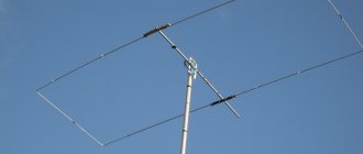
Antennas of the “wave channel” type have a relatively narrow directivity lobe to the transmitting station, which is simultaneously combined with a high gain. These indicators are inextricably linked and directly depend on the number of links and the length of the antenna structure.
Note! As the dimensions of the product increase, its weight increases, which negatively affects the strength of antenna devices.
All these disadvantages can be overcome by using an antenna similar in design to a wave channel with a log-periodic arrangement of dipoles. Both of these varieties are capable of efficiently processing a signal only if the active elements are manufactured and placed with the utmost precision.
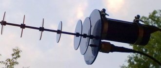
Another modification of simple-to-use household antennas for digital TV is a half-wave vibrator, which is an open quarter-wave line, the individual parts of which are located in one straight line (see figure).
Half-wave vibrator
This element is an integral part of most of the antenna equipment considered here.
Of particular interest are universal delta television antennas, designed specifically for receiving frequencies in almost the entire range of received waves (MV plus UHF). With some reservations, they can also be classified in the same class as those discussed earlier.
Some samples of these products are designed for installation within a room, and some of them can be installed outside the room on a balcony, for example (street design). The difference between these two designs is the different number of stacked elements (dipoles), as a result of which they are somewhat different in size and weight.
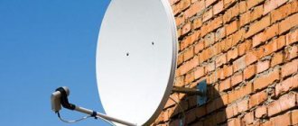
Naturally, an internal or indoor antenna does not have the same performance as an external one, however, it is quite suitable for receiving a signal from a not very distant television center (see photo of the external structure below).
Outdoor antenna "Delta"
TV antenna Delta
The Delta television antenna, produced by the Research and Production Association of Equipment and Communication Systems, has been in deserved demand among users in Russia and the CIS countries for many years. The product range includes devices in the meter range, decimeter range and broadband, amplifying signals in both ranges - VHF and UHF; collective antennas and individual use; outdoor and indoor, log-periodic and wave channel.
Model table
The table shows the characteristics of individual outdoor broadband television antennas Delta.
All of them are designed to receive TV channels 1 to 60 and are designed for viewing both analog and digital broadcasts. The letter A means that this is an active Delta antenna with an amplifier. Some models, for ease of connecting the antenna cable, are equipped with F-connectors and are designated by the letter F. Table: Delta television antennas
| Models | Peculiarities | Gain kit |
| H3311 | Symmetrical vibrator MV and log-periodic UHF | 0/1/9 |
| N3311A | Analog H3311 - with amplifier | 20/20/26 |
| N311.02 | Symmetrical vibrator MV and log-periodic UHF | 0/1/8 |
| H311.02F | Symmetrical vibrator MVI log-periodic UHF, F-connector | 0/1/8 |
| Н311A.02F | Analog H311.02F with amplifier | 20/20/26 |
| N311A.02 | Analogue N311.02 active | 20/20/26 |
| H1321 | Analog H321, aluminum | 1/1/4 |
| Н1321А | Analog H1321 with amplifier | 20/20/25 |
| H391 | Horizontal polarization | 1/6/8 |
| H391A | Similar to H391 - delta antenna with amplifier | 20/26/28 |
| N311A1 | A1- UHF amplifier | 0/1/20 |
| H341 | 0/1/11 | |
| H341A | Analog H341 active | 1/2/10 |
| H311-01 | 22 elements | 0/1/8 |
| N311A-01 | Analogue N311-01 with amplifier | 20/20/25 |
| H351 | 34 elements | 0/0/12 |
| H351A | Analog H351 active | 0/0/12 |
| H361 | 42 elements | 1/6/11 |
| H361A | Analog H361 with amplifier | 20/24/30 |
| H321 | 14 elements | 0/1/4 |
| H321A | Analog H321 active | 20/20/25 |
| N321A1 | Analog H321 with UHF amplifier | 0/1/16 |
| H375 | 43 elements | 3/6/11 |
Delta antenna with amplifier
Purpose - individual reception of television broadcast signals of horizontal polarization in the frequency range from 48.5 MHz to 790 MHz from television channels 1 to 60.
The Delta H311 antenna ensures viewing of television programs in an area of reliable reception, the active model H311A with a built-in amplifier is used in an area of a weak signal from a television center. The range and quality of reception depend on the installation location and height, the power of the television transmitter, the terrain and the level of electronic interference. The delta antenna with an amplifier is configured to receive television signals in accordance with the table of frequencies of television channels of terrestrial television, given in the section Terrestrial television channels."
Delta H311 antenna design
TV antenna Delta
H311 is an antenna module - a log-periodic design for decimeter waves and two vibrators for receiving meter waves. The device is mounted on a mast and is oriented towards the television center using a fastening unit. The antenna box contains a matching board, or antenna amplifier model H311A.
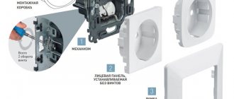
Assembly and installation procedure
Antenna Delta N 311-01 connection diagram. First of all, meter range vibrators are assembled and connected to the antenna box. Next you need to connect the antenna cable, for which you need to remove the protective sheath, shielding braid and internal insulator, freeing them by 10 mm. Make the connection: remove the cover of the antenna box, unscrew the nut securing it, insert the cut end of the cable into the central hole and connect it to the matching board. Install the H311 assembly on the mast and secure it at a height sufficient for direct visibility to the television tower. By rotating the device in one direction or another, use the best image to determine the optimal orientation angle and secure it completely. Fix the antenna cable on the mast, connect the grounding wire to the nut on the grounding stud located on the mounting unit.
Indoor antenna Delta
Delta indoor antennas are designed for receiving television signals indoors; their design and modifications are described in the section
"indoor antennas with amplifier."
Delta design and parameters
It is known that the delta antenna has the properties of several types of devices at once, since its design is a combination of a half-wave and log-periodic dipole. This feature makes it possible to implement in one product the possibility of all-wave signal reception from transmitting stations.
DIY 4G antenna for modem
These receivers take advantage of both types of designs; Moreover, the various parts of the structure are perfectly coordinated with one another. As a result of this combination, it is possible to obtain a universal antenna with minimal losses from the mutual influence of individual components and improved reception characteristics.
Important! At the same time, the developers managed to agree on the parameters of the supply cable, suitable for all existing frequency ranges.
An outdoor antenna of this class has the following main characteristics:
- Received frequencies cover the MV and UHF ranges;
- Effective gain (CA) – 3-14 dB;
- Attenuation coefficient (AC) in the lateral and rear directions – 12 dB;
- The characteristic impedance of the cable is 75 Ohms.
Additional Information. The KZN in this design refers only to the decimeter component of the entire antenna.
The spread in gain values indicates different gain levels for different parts of the frequency range, and dips mainly occur on meter channels. Since modern television broadcasting has a steady tendency to reduce them, there is no need to worry about this at all.
To increase the KZN in the UHF range, it is possible to modify the Delta antenna, which consists of equipping it with a special reflector, which is placed between the meter and decimeter parts. Those who have converted their antenna into a reflector know well that this element is made in the form of a special grating that attenuates the signals from the rear lobe, thereby increasing the overall gain (see photo below).
Delta with reflector
Note that all the parameters discussed above relate to passive types of antennas that do not have built-in television signal amplifiers or are designed as a separate module. As a result, the scope of application of such structures will be limited to areas that have direct visibility to the transmitting equipment.
Instructions and files
| File | Pages | Format | Size | Action |
The cable can be connected to a log-periodic passive antenna (LPA) without a special matching device. A cable with a characteristic impedance of 75 Ohms is inserted into the down tube at one end and exits at the other. The cable braid is soldered to the end of the lower pipe, and the central core is soldered to the end of the upper pipe.
The modified antenna was tested at a distance of 70 km from the repeater indoors, with an antenna height from the ground of 2.5 m, the transmitter power is unknown.
Connection procedure
DIY Mimo 4g lte antenna
To understand how to properly connect Delta to a television receiver, please note that this procedure is practically no different from connecting any other device of a similar purpose.
In order to connect it correctly, you first need to cut the mating end of the cable wire for a contact connector or soldering. This operation is necessary in order to arrange it in the form of a standard plug connector, which will be used to connect to the input jack of the receiver.
If a model with a built-in amplifier is used, its design must include another wire designed to connect the delta antenna to the power supply adapter (see the figure below).
Connection diagram
Important! When connecting a cable to a plug, under no circumstances should a short circuit be allowed between the screen braid and the thin central core.
When carrying out the described procedures, it is recommended to follow the instructions for designing television connectors, which should contain a connection diagram.
Features of operation
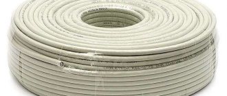
Long-term operation of Delta type antennas in the open air requires careful sealing of the input and connection areas of the cable and wire. If there are no traces of treatment with protective agents on the product, you must perform this operation yourself (taking into account the capabilities of this model).
Moisture getting inside the amplifier circuit or on the contact connections can lead to failure of the entire structure, and the cable connected to it can become completely wet in conditions of high humidity. Possible consequences of these operational violations are a short circuit in the power circuits and complete burnout of the entire electronic part of the device.
Additional Information. The only correct way out of this situation is to completely replace the soaked cable along with the antenna plug.
Drying a wet cable product is unacceptable, since over time it will still fail due to the presence of internal elements damaged by corrosion (braided shielding, in particular).
In the event of a noticeable deterioration in the quality of reception on all or several television channels (or its complete loss), you should disassemble the plug and make sure that the wiring of the central core and braid are in good condition. If serious violations are detected, it is necessary to cut off the cable near the damaged connector and make a new contact connection in the form of an antenna plug.
In conclusion, we note that to independently assemble a Delta-type antenna, you need an appropriate level of training and skills to work with devices of this class. There is not enough professional data for this on the Internet, since all the information presented in the sections on this topic concerns mainly amateur radio samples.