The operation of various modern means of communication is impossible without such devices for receiving and transmitting radio waves as short-wave antennas (abbreviated as HF antennas). The demand and popularity of these devices is due to the wide variety of their types, as well as the possibility of self-production. They are especially common in amateur radio communications with the permitted broadcast range from 1.81 to 29.7 MHz.
Classic HF antenna
Helix antennas
DIY Mimo 4g lte antenna
The classic device of this type (“Tesla Spiral”) consists of two spirals located on crosspieces connected to each other by a jumper (traverse).
Tesla Spiral
Antenna power
Such a device is connected to a transceiver (receiving and transmitting equipment) with a thick coaxial cable with a characteristic impedance of 50-75 Ohms.
Antenna assembly
A small device of this type is assembled by winding two flat spirals with a diameter of 90 cm onto a frame made of polypropylene pipe, consisting of two crosses and a 90-92 cm crossbar connecting them. Single-core insulated copper wire with a diameter of 1.5 mm is used as the material for the spirals.
Transformer
For this device, an air transformer is used with an operating wave range from 10 to 100-160 meters. It is made by winding 16 turns of double wire 1.5 mm thick onto a hollow 140 mm frame with a diameter of 25 mm. The length of the wire winding should be 95-100 mm.
Antenna setup
The setup process includes the following operations:
- Setting the SWR (standing wave ratio) is done using a special device or alligator clips fixed on the vibrator spirals and moved along them, which leads to a change in the position of the power point. The VSC value obtained during tuning at the found frequency should be within 1.0-1.2.
- Adjusting the resonance frequency is done by changing the length of the vibrator wires using the same clamps as in the previous paragraph. The adjustment is made by moving the clamps along the insulated wire of the spirals.
Antenna gain, bandwidth and beam angle
The helical transmitting antenna is placed horizontally at a height equal to 1/8 of the wavelength it emits.
Assembling the antenna
So, to create we need:
- Plumbing plastic coupling. Suitable with a diameter of 50-55 centimeters.
- SO-239 connector.
- Plumbing plugs commensurate with the previously selected coupling.
- Three ring screws.
- Three nuts and six washers.
In the coupling, we make a plug for fastening of 6 millimeters and for the connector of 16 mm. The balun can then be connected or assembled. We will imagine that we don’t want to buy. Therefore, we take a ferrite ring with a permeability of 600, a piece of wire with a cross-section of 0.5-1 mm. We fold the wire in three and begin to wind it around the ring. After a full-fledged CB antenna coil is ready, the winding is fixed using insulating tape or clamps. We mount the balloon into the blank, and then solder the connector. The structure is almost ready. It remains to measure the required number of wires for the best antenna in order to secure them to the workpiece. Thickness doesn't matter here. As an example, you can take three meters of 1.5 mm. By the way, although the program calculated that the optimal value is 2.57, it is better to take a little with a reserve. That's why it's three meters. We solder everything - and our antenna is ready.
Magnetic antennas
DIY digital TV antenna
The most common HF antenna design is a magnetic loop , consisting of:
- Duralumin or copper radiating ring with a diameter of 25-80 cm;
- Communication loops, the diameter of which is 5 times smaller than that of the radiating ring;
- Supply cable (feeder) with a characteristic impedance of 50 Ohms;
- A powerful capacitor adjusts the resonant frequency.
Magnetic frame loop
Such simple homemade transmitting devices are installed both on high masts, roofs of high-rise buildings, and on balconies or window sills of apartments. Thanks to a tuning capacitor capable of operating at a power of up to 100 W, such amateur radio shortwave antennas operate in the range from 1.8 to 27 MHz.
HF Antennas
Radio amateurs have been using the Windom antenna for almost 90 years, which got its name from the name of the American shortwave operator who proposed it. Coaxial cables were very rare in those years, and he figured out how to power an emitter half the operating wavelength with a single-wire feeder.
It turned out that this can be done if the antenna feed point (connection of a single-wire feeder) is taken approximately at a distance of one third from the end of the emitter. The input impedance at this point will be close to the characteristic impedance of such a feeder, which in this case will operate in a mode close to the traveling wave mode.
The idea turned out to be fruitful. At that time, the six amateur bands in use had multiple frequencies (non-multiples of WARC bands did not appear until the 70s), and this point turned out to be suitable for them as well. Not an ideal point, but quite acceptable for amateur practice. Over time, many variants of this antenna appeared, designed for different bands, with the general name OCF (off-center fed - with power not in the center).
In our country, it was first described in detail in the article by I. Zherebtsov “Transmitting antennas powered by a traveling wave,” published in the journal “Radiofront” (1934, No. 9-10). After the war, when coaxial cables came into amateur radio practice, a convenient power supply option for such a multi-band emitter appeared. The fact is that the input impedance of such an antenna in the operating ranges does not differ very much from 300 Ohms. This allows you to use common coaxial feeders with a characteristic impedance of 50 and 75 Ohms through HF transformers with a transformation ratio of 4:1 and 6:1 to power it. In other words, this antenna easily became part of everyday amateur radio practice in the post-war years. Moreover, it is still mass-produced for shortwave frequencies (in various versions) in many countries around the world.
It is convenient to hang the antenna between houses or two masts, which is not always acceptable due to the real circumstances of housing, both in the city and outside the city. And, naturally, over time, an option arose to install such an antenna using just one mast, which is more feasible to use on a residential building. This option is called Inverted V - Windom.
The Japanese shortwave operator JA7KPT, apparently, was one of the first to use this option for installing an antenna with a radiator length of 41 m. This length of the radiator was supposed to provide it with operation in the 3.5 MHz range and higher frequency HF bands. He used a mast 11 meters high, which for most radio amateurs is the maximum size for installing a homemade mast on a residential building.
Radio amateur LZ2NW (https://lz2zk. bfra.bg/antennas/page1 20/index. html) repeated his version Inverted V - Windom. Its antenna is shown schematically in Fig. 1. The height of his mast was approximately the same (10.4 m), and the ends of the emitter were spaced from the ground at a distance of about 1.5 m. To power the antenna, a coaxial feeder with a characteristic impedance of 50 Ohms and a transformer (BALUN) with a coefficient of transformation 4:1.
Capacitive antennas
Multiband antenna
A multi-band antenna is a device that allows broadcasting in all short wave bands permitted for amateurs. Thanks to this property, multi-bands have become very popular and widespread.
One of the UA1DZ type multi-bands has the following design:
- Vibrator 9.3 m long
- 3-meter stand;
- 4-5 quickdraws;
- 10-14 additional flexible counterweights, 9.4 m long.
The connection of such antennas and transmitters is made using a 50 Ohm coaxial cable.
The main disadvantages of such multi-band structures are their bulkiness, high windage and the risk of lightning when installed on the roof of a high-rise building or other multi-story building.
Vertical Antenna (Ground Plane)
Vertical Ground Plane antennas are devices designed for broadcasting in the ranges from 14 to 24-28 MHz. The main components of such vertical HF antennas are a 2-meter mast, a duralumin vibrator 2 to 5 meters long, 4-5 counterweights 2.5-3 meters long and a 50-ohm coaxial supply cable.
They are installed both on the roofs of high-rise buildings and on the gables of private houses.
Short dipole antenna
The simplest device of this type at 7 MHz is a structure consisting of the following parts:
- A wire vibrator divided into two 3-meter arms with insulators and guys at the ends. Small pieces of textolite are used as insulators; durable nylon linen cord is used for guy ropes.
- Two extension 140-turn coils made of copper wire 0.5-0.6 mm thick;
- Central unit with transformer (balun);
- Feeder – 50 Ohm supply coaxial cable.
Short dipole
Such a shortened dipole is used both in stationary and field conditions, fixing it at a height of 3 to 4 meters.
On a note. In order to tune such a device for resonance, it is necessary to uniformly shorten the length of the horizontal or angled arms of the vibrator. After changing the length of the arm, the guy that shortens it is attached to the nearest tree or other stable support.
Very simple option
We will make it from scrap materials. From the purchased ones - only UNF connectors and RG-58 cable. The antenna surface will be equal to the wavelength. By adjusting it to resonance, it can be shortened and made a little longer. If the transmitter is coaxial, then the power supply must be balanced. The easiest way is to use low-frequency ferrite (from 400 to 2000 NN). When creating a CB antenna with your own hands, a transformer from a computer power supply can play its role. It should be noted that standard yellow rings will not fit, so two turns of cable must be wound around the core. And here one question becomes relevant. Namely, which antenna cable to choose? Let's assume that we need an optimal solution in the price/quality coordinate system. In this case, you can pay attention to a regular piece of wire ShVVP 2X0.75. It is divided into two conductors, which are soldered together. The total length should be eleven meters. At the same time, maintaining equality of arms is not a critical point. As an insulator, you can use a plastic ring - for example, from a baby rattle.
DIY vertical HF antenna
The most popular for DIY production are short-wave transmitting devices such as vertical antennas.
The simplest and most effective of them is done as follows:
- A wooden column 2.5-3 meters high is dug into the ground;
- The distribution box is secured to the buried post using self-tapping screws;
- A high-frequency choke is placed in a fixed box - a coil with turns of insulated coaxial cable wound on it;
- A two-core stranded copper cable with a cross-section of 2 mm is connected to the inductor output;
- The wire is threaded through the guide rings of a cheap 6-meter carbon fiber rod;
- The end of the wire is secured to the tip of the rod using a regular plastic tie;
- A round platform with guy wires is fixed in the middle of the rod;
- On the top of the post, 2 clips and one clamp holder (KTR) for polypropylene pipes with a diameter of 32 mm are attached;
- Using clips and a holder, the rod with the emitter (wire threaded through the guide rings) is secured to the pole;
- Using guys, the mast with the emitter is leveled and securely fixed. Guys are secured to stable, nearby poles, trees, and hooks screwed into the supporting structures of buildings and permanent structures.
The supply wire for HF antennas of this type is used with a characteristic impedance of 50 Ohms.
Maintenance of such a device comes down to periodically checking the integrity of the emitter by testing it with a multimeter, replacing mast knees broken by the wind, and adjusting the tension of the guys.
ANTENNAS FOR SHORT AND METER WAVES
to contents
|
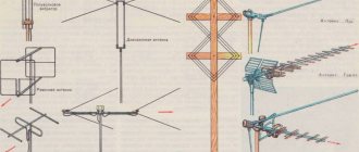
Let's look at the most common antennas for short and meter waves (and sometimes for medium waves), used both as transmitters and receivers.
Whip and vertical antennas. Portable and mobile radio stations for operation over short distances use a whip antenna, which is a metal vertical rod made up of several parts (elbows) and usually installed on the radio station itself (Fig. 1 a).
Fig. 1 - Whip antenna and current distribution in it
To increase the range of action, an asterisk or whisk is mounted on the top of the pin, which slightly increases the antenna capacity and changes the distribution of current in the pin. Without an asterisk, there will be a current node at the upper end of the pin (I = 0), and with the presence of an asterisk, the current node will shift to the ends of its rays and, therefore, at the end of the pin, the current and radiation will not be equal to zero (Fig. 1 b).
The counterweight for a whip antenna is usually the metal body of the radio.
A greater range is provided by a vertical antenna in the form of a metal mast or in the form of a vertical wire suspended on a wooden mast (Fig. 2). The counterweight for a vertical antenna is usually made of several wires located low above the ground.
Fig.2 - Vertical antenna
Whip and vertical antennas do not have a directional effect in the horizontal plane. Dipole antennas. These antennas for portable low-power radio stations consist of two wires of the same length, stretched in one line (Fig. 3). A low-lying dipole gives the greatest radiation and best reception in the direction in which the beams are stretched, and the least radiation and worst reception in the direction perpendicular to the beams.
Fig. 3 - Dipole antenna
When operating over short distances, dipole beams, if made of insulated wire, can even be extended onto the ground. To increase the range, the beam included as an antenna is raised to an inclined position, and then the maximum radiation will be towards the counterweight.
For communication over long distances, the dipole is placed high above the ground, and antennas consisting of several vibrators are also used. The length of the vibrator must be selected depending on the ratio of the wavelength (lambda) to the wire diameter d. So, for example, if (lambda)/d = 40, then L = 0.47(lambda), and if (lambda)/d = 1000, the length of the vibrator should be 0.485 (lambda). A vibrator made of thin wire has a higher quality factor, and therefore a narrow frequency band of transmitted vibrations. If it is desirable to expand this band so that the vibrator works well within a certain range, it is made of rods or tubes with a diameter of 10-30 mm.
Fig. 4 - Antennas powered by a standing wave
When the distance from the transmitter or receiver to the antenna is short, standing wave feeders can be used. For example, antennas with short feeders operating in standing wave mode are used for mobile radio stations on cars, airplanes, etc. The simplest antennas with such feeders are shown in Fig. 4. In the antenna (Fig. 4 a), the vibrator has symmetrical power supply at the current antinode (current power supply), in which its input impedance is about 80 ohms. The length of the feeder in inductive coupling with the transmitter or receiver circuit must be equal to an integer number of half-waves, so that there is a current antinode in the coupling coil La. In practice, the feeder length is always taken 5-10% less than the calculated one.
Asymmetrical voltage supply to the antenna is shown in (Fig. 4 b). The feeder is connected with only one wire to the end of the vibrator. Since at the antinode the voltage Zin is very large (like an open line with a length of 1/2 (lambda)), the feeder operates in the standing wave mode and its length should be an odd number of quarters of a wave.
In (Fig. 4c), the vibrator is powered with voltage using a coaxial cable. The vibrator itself, when powered according to (Fig. 4 b and f), can be located at an angle from 90 to 180° to the feed line. The voltage supply can be symmetrical if it is used for two in-phase vibrators. This power supply circuit is widely used in complex common-mode antennas (Fig. 4d), which produce highly directional radiation. Such antennas were first developed and studied by Prof. V.V. Tatarinov. They have several antenna vibrators in which the currents are in phase, and usually the same number of reflector vibrators.
Vibrators can be located both horizontally and vertically. Taking into account the polarization of the waves, the condition must be met that the vibrators of the transmitting and receiving antennas are parallel to each other. To simplify the design, a metal mesh is often used as a mirror, located at a distance of 1/4 (lambda) from the active vibrators. A metal sheet can also serve as a mirror, but the mesh has less weight and there is less wind pressure on it, which is important for large antenna sizes.
Fig. 5 - Complex common-mode antenna of 16 vibrators with a mirror (the mirror grid is not completely shown)
Active vibrators in complex antennas are usually powered using an extensive system of feeders. Figure 5 shows a complex common-mode antenna with 16 vibrators arranged horizontally and a grid-shaped mirror. To obtain in-phase operation of the vibrators, each feeder going from one pair of vibrators to another pair is crossed. This is necessary to compensate for the 180 phase shift resulting from the fact that the distance between two adjacent pairs of vibrators is 1/2 (lambda).
Feeders that distribute energy in such an antenna operate in mixed wave mode since the feeder is connected to two in-phase vibrators at voltage antinodes, in which the input impedance of the vibrator is high. It is thousands of Ohms, i.e. much greater than the wave impedance of the feeder.
When the antenna is significantly removed from the transmitter, the feeder must operate in traveling wave mode, which is achieved by matching the feeder with the antenna. The simplest is to power the vibrator with current using a coaxial line having Zo = 70-80 ohms, i.e. approximately equal to Zin of the vibrator (Fig. 5 a). However, the coaxial line, being asymmetrical, violates the symmetry of the vibrator and impairs its performance.
In (Fig. 5 b and c), the vibrator is powered by two-wire and single-wire feeders connected at points A and B located between the current antinode and the voltage antinode. At these points, the input impedance of the vibrator is the average between its lowest value Zin = 80 Ohm at the current antinode and the highest value at the voltage antinode. Points A and B are selected so that Zin = Zo. The dimensions shown in Fig. 5 refer to the operation of antennas on the fundamental wave, but they can also be excited on some harmonics.
The antenna in (Fig. 5 b) is symmetrical. The part of the feeder with the diverging wires is the resistance transformer (sometimes called a delta transformer). As the distance between the wires 20 of the line increases, it increases and at points A and B it is equal to Zin of the vibrator.
The widely used loop or stub antenna, proposed by A. A. Pistolkors, has great advantages. It consists of two closely spaced parallel half-wave vibrators, closed to each other at the ends, with current supply at the antinode of one of them (Fig. 6). The currents of both vibrators coincide in direction, and therefore such an antenna is equivalent to one vibrator with double the current.
Fig.6 - Loop vibrator of A.A. Pistolkors
The radiation resistance, and therefore the input resistance, of a loop antenna is approximately four times greater than that of a conventional vibrator, and is about 320 ohms. With this value of Zвx, it is possible to obtain coordination with a symmetrical feeder, in which the ratio of the distance between the wires to the diameter of the wires is b/d = 6-8. The loop antenna is more broadband than a conventional vibrator.
Fig. 7 - Antenna with reflector and director
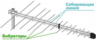
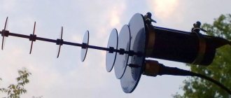
To obtain a sharper directivity, an antenna with a reflector and a director (Fig. 7), as well as with several directors (Fig. 8), called a “wave channel” antenna, or director antenna, is often used.
Fig.8 - Director antenna
In such antennas, the main emitter is a conventional half-wave vibrator, or loop antenna. To obtain the best results, the antenna is often adjusted experimentally, determining the nature of its radiation using a field strength indicator. The presence of passive vibrators (reflectors and directors) reduces the input impedance of the antenna. In practice, the distance between vibrators can be in the range from 0.1λ to 0.25λ. The dimensions shown in Fig. 7 and 8 are not the only possible ones, but approximate.
The directional action of antennas is characterized by the directional coefficient (knd), introduced by A. A. Pistolkors in 1929. It shows how many times the radiation power must be increased when moving from a directional antenna to an omnidirectional one in order to maintain a constant field strength at the receiving location.
In this case, an omnidirectional antenna is understood as some imaginary antenna that radiates equally in all directions. In practice, such an antenna does not exist, even a half-wave vibrator, which has the lowest directivity compared to other types of antennas, has a coefficient of gain equal to 1.64. The knd values, of course, refer to the case when radio communication is carried out in the direction of the main maximum of the radiation pattern.
For director antennas, the value of the cand is approximately equal to the number of directors multiplied by 5. For modern complex highly directional antennas, the cand can have values of up to several thousand.
If it is intended to conduct radio communication in different directions using a directional antenna, then the antenna is rotated
using cables from the room in which the radio station is located. To match the feed line with the antenna, various devices are used, of which we will consider the two most common.
1.
A quarter-wave transformer is a quarter-wave line connected between the main line and the antenna and works as a resistance transformer (Fig. 9).
Fig. 9 - Matching the line with the load through a quarter-wave transformer
Let us assume that the main line has a characteristic impedance Zo, but the load resistance R is not equal to Zo. It turns out that the input resistance of the transforming quarter-wave line, i.e., the resistance at points A and B, is equal to
where Zot is the characteristic impedance of the transforming line.
By selecting the value of Zot, one can obtain Zab = Zo. Then in the main line (to the left of points A and B) the traveling wave mode will be obtained, and the mixed wave mode will be only in the short transforming line (to the right of points A and B). The required Ζot can be determined using the formula
For example, if Ζο = 320 ohms, and the load resistance is Ζin of the vibrator, equal to 80 ohms, then Ζοτ = 160 ohms. For this case, Fig. 9 shows the distribution of current and voltage along the line. In a transforming line
Therefore, the current and voltage along this line change twice, and the current towards the end of the line increases and the voltage decreases. At the end of the line
At the beginning of the line, the voltage is twice as high and the current is half as large as at the end of the line. From here
Thus, the quarter-wave line converts a load resistance of 80 ohms into 320 ohms and creates kbv = 1 in the main line. And without a matching device in the main line, the result would be kbv = 0.25.
To obtain the required characteristic impedance, select the distance between the wires of the transforming line b or the diameter of the wire d, or both, so that the ratio b/d corresponds to the desired value of Zot. For coaxial lines, the required value of Zot is obtained by selecting the ratio of diameters.
2.
The U-elbow is used to match an asymmetrical coaxial feeder with a symmetrical antenna. The U-elbow design in its simplest form is shown in Fig. 10. It is a piece of coaxial cable connected from its beginning at point A to the end of the coaxial feeder and to one half of the vibrator. The other end of the U-elbow is connected to the wire of the second half of the vibrator (point B).
Fig. 10 - Diagram of the U-elbow device
The outer wires (sheaths) of the feeder and U-bend are short-circuited.
In order for the wave passing through the U-bend to point B to be 180° out of phase from the wave at point A, the length of the U-bend a must be
where λ is the operating wavelength, and ε is the dielectric constant of the insulator used in the cable. Most coaxial cables, which have a solid dielectric between the inner wire and the sheath, have є = 2.3 and therefore L = 1/3 λ.
Since the phases are opposite at points A and B, a symmetrical load in the form of a vibrator can be attached to these points. Moreover, if the characteristic impedance of the feeder is equal to Zo, then the resistance between points A and B is equal to 4Zo. To obtain matching, Z8X of the vibrator must also be equal to 4 Zo. For example, when using a coaxial feeder with a characteristic impedance of 80 ohms, it is convenient to feed a single loop vibrator having Ζin = 320 ohms through the U-elbow. If Ζin of the vibrator differs significantly from 4Zo, it is necessary to turn on a matching quarter-wave transformer between the U-elbow (points A and B) and the vibrator.
to contents
Did you know,
that any reasonable person will say that there cannot be a smile without a cat and smoke without fire, there must be something warm out there in space, emitting EM waves, corresponding to a temperature of 2.7ºK. Indeed, the observed cosmic microwave radiation (CMB) is the thermal radiation of ether particles having a temperature of 2.7ºK. At the beginning of the twentieth century, the great chemists and physicists D.I. Mendeleev and Walter Nernst predicted that such radiation (temperature) should be detected in space. In 1933 prof. Erich Regener from Stuttgart measured this temperature using stratospheric probes. His measurements gave 2.8ºK - an almost exact modern value. Read more in the FAQ on ethereal physics.
Selecting the first HF transceiver
When choosing the first transmitting device (transceiver), novice radio amateurs need to consider:
- Dimensions and weight - the radio station must have such dimensions and weight that it can be easily carried in hands or in a backpack.
- Functionality - for a beginning radio amateur, a transceiver with a small number of basic settings (resonant frequency, power, SWR) is sufficient;
- Reliability and warranty - like any other equipment, a shortwave radio station must have a warranty period;
- Possibility of programming equipment using a personal computer.
Transceiver
Beginner radio amateurs are not recommended to purchase expensive shortwave radio stations that are very difficult to operate and maintain. It will be very difficult for a beginner who is interested in amateur radio to understand such equipment; if they lose interest in this matter, selling such an expensive radio station for the same amount as it was purchased will be very difficult.
Other antenna designs
Among other HF antenna designs, the vertical spiral half-wave vibrator for waves 80 meters long, consisting of:
- 120-centimeter spiral made of insulated copper wire with a diameter of 1-1.5 mm;
- Traverse height 150 cm;
- Counterweight with a length of at least 80 cm;
- Matching device;
- High frequency autotransformer;
- The supply line is made of coaxial cable with a characteristic impedance of 50 Ohms.
Such vertical antennas are used in conditions of limited space in small garden plots, on the roofs of multi-storey buildings and other high-rise buildings.
Selecting the type of HF antenna
Depending on the installation location and the capabilities of the buyer, the choice is provided by three main types of HF antennas:
- Vertical installation with a circular radiation pattern;
- Dipole (parallel to the ground);
- Directional design.
In all three cases, it is impossible to get as close to the wavelength as possible. Especially in multi-range designs. Therefore, we need to look for a compromise. Directional designs have a better gain, but they are quite expensive and complex, requiring special rotation devices and mast equipment, which not everyone can afford. Structures installed parallel to the ground are less expensive and longer, which brings them as close as possible to the transmitting wavelength, but nevertheless, it is not always possible to install them high enough from the ground and they have lower efficiency compared to narrowly directed ones. Verticals are the most compromise option, which does not require large investments in the installation location of the HF antenna, but have the lowest efficiency characteristics.
HF Antenna Users
Unfortunately, due to the specifics of HF radio communications, the number of those who can use them is increasingly decreasing. But the main participants in HF communications are:
- Radio amateurs;
- Military;
- Rescuers (Ministry of Emergency Situations);
- Meteorological Services;
- Expeditions.
Any of the listed users will be able to choose the right antenna in our price list that will satisfy all their needs.
A few words about shortwaves
Shortwave
Shortwave operators are radio amateurs who broadcast in the shortwave range. People involved in the design, manufacture and repair of transmitting devices conduct communication sessions from different parts of the planet. In this case, for each of them, the achievement is considered to be the farthest point from which a radio communication session was conducted.
On a note. According to the current legislation of the Russian Federation, broadcasting is available for shortwave radio amateurs on 10 shortwave bands with the following wavelengths: 2200 m, 160 m, 80 m, 40 m, 30 m, 20 m, 16 m, 15 m, 12 m, 10 m. The use of high frequency bands is prohibited.
Antennas
Other antennas Amplifiers Wi-Fi antennas For TV Satellite Miscellaneous for antennas
The simplest antennas for digital television
To receive digital TV, you need a TV with a digital tuner of the DVB-T2 standard or any other TV, plus a DVB-T2 set-top box, which is a free-standing digital tuner and connects to the TV via low frequency (like a VCR or DVD player). Well, and also - you need an antenna...
1 626 0
Shortwave (HF) camping antenna
Diagram and design of a homemade camping shortwave antenna for 7, 14, 21 and 28 MHz. Nowadays, shortwave operators, when going on hikes in their native land, often take an amateur radio station with them. Polish radio amateur SQ7MZL has developed a simple collapsible ...
1 1087 0
Homemade antenna for digital DVB-T set-top box
Now the country is switching to digital TV, and commercial enterprises are reacting to this rather strangely, although expectedly. For example, these “antennas for digital TV” have appeared, which for some reason are more expensive than exactly the same UHF antennas. However, to receive digital TV you need a regular UHF...
0 565 0
Digest on amateur antennas (selection of diagrams and designs)
Unidirectional antenna for 6 m band The most common type of cross-shaped antenna for the 6 m band (50.5 MHz) is shown in Fig. 1. The dipoles are installed at right angles to each other. To obtain a phase shift of 90°, a phasing line is used. There are more complex methods for obtaining ...
1 1918 0
A simple homemade indoor HF antenna (resonant)
Any radio amateur knows: a short-wave receiver without an antenna is not a receiver, and good antennas are never small. Finding a place for an antenna in a city is not so easy. I offer a description of a simple antenna that does not take up much space and at the same time has good characteristics...
1 4113 0
Homemade transmitting antenna for medium wave range 200 meters
Setting up a mid-wave transmitting antenna in an urban environment is not an easy task. An extended wire antenna will always be tied to the surrounding buildings, so there can be no universal recipe for the “correct” antenna. Often happens in urban areas when...
1 2316 0
A simple television antenna made from affordable materials
With the growing popularity/volume of digital broadcasting in the DVB-T format, which is conducted on the UHF bands, many antennas specifically for digital channels have appeared on sale, according to sellers. You can buy it. No problem. How about doing it yourself, with your own hands? Moreover, from components that...
1 1714 0
Combined TV antenna for receiving TV channels from 6 to 60
In connection with the expansion of television broadcasting in higher frequency ranges, the need arose for a small-sized broadband antenna for receiving TV channels from 6 to 60. The article [1] helped to implement it, which describes a broadband antenna for receiving television broadcasts throughout the meter...
1 1526 0
UHF Antenna Solnyshko
A broadband (21...60 TV channels) UHF antenna can be easily made, for example, from two duralumin (with cross-shaped “spokes”) disks of old reels for magnetic tape of stationary tape recorders. To do this, you need to place disks 1 on top of each other so that the chamfers of the disk holes...
1 1517 0
Acoustic set-top box for color TV with connection via video input
The article [1] described a device that creates light effects on a television screen in time with the sound of the program, which should be connected to the inputs of video amplifiers of channels R, G and B of a color TV. This connection method creates a number of inconveniences, since you have to remove...
1 1306 0
1 …
Mobile phone antennas
Not so long ago, many mobile phone models used directional antennas that were quite large for these devices. However, as telecommunications technologies developed, the operation of mobile communications gradually moved from shortwave to HF bands up to 2500 MHz. This operating frequency corresponds to a wavelength of only 12 cm, so for effective communication sessions a small transmitting device built into the phone is sufficient.
Thus, a correctly assembled, installed and tuned short-wave antenna is the key to stable and high-quality communication with radio amateurs living in the most remote corners of the planet. Thanks to the wide variety of designs and models, such a transmitting device, assembled from scrap materials, can be installed in almost any accessible place: on the roof, balcony and even inside a living space.
Video
Coffee capsule Nescafe Dolce Gusto Cafe O Le Coffee with milk, 3 packs of 16 capsules each
1305 ₽ More details
Coffee capsules Nescafe Dolce Gusto Café Au Lait, 16 pcs.
435 ₽ More details
Shockproof smartphones