Flat capacitor
There are many types of capacitors with different shapes and internal structures. Let's consider the simplest and most fundamental - a flat capacitor. A flat capacitor consists of two parallel conductor plates (plates), electrically insulated from each other by air or a special dielectric material (for example, paper, glass or mica).
How to correctly calculate the capacitance of a capacitor?
The simplest example of a capacitor is a flat model. It has the shape of two parallel covers made of a conductor, between which there is a dielectric layer. In order to know how to calculate the capacitance of capacitors, you need to apply the following formula:
You may be interested in this Transition from 380 to 220 volts
C = ex e0 xs / d,
where S is the surface area of the plates and d is the distance between them. In turn, this is the relative electrical permittivity of a given dielectric.
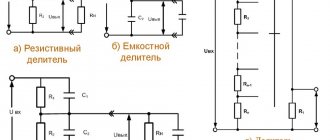
As a rule, capacitors are not used individually, but are connected to larger systems. They can be connected in series, parallel or mixed.
Capacity formula
Important! In series-connected elements, the absolute value of the charge on each plate is identical.
Thus, the resulting voltage is equal to the sum of these indicators on the individual components of the device.
The total capacity of the system will be determined by the formula:
1/С = 1/С1 + 1/С2 + 1/С3 + …
When connected in parallel, the potential difference on each part is the same. Thus, the total charge will be equal to the sum of the charges on the components of the capacitor, and the resulting capacitance will be equal to the sum of the individual unit values:
C = c1 + c2 + c3 + …
Capacitor charge. Current
In terms of its purpose, a capacitor resembles a battery, but it is still very different in its operating principle, maximum capacity, and charging/discharging speed.
Let's consider the principle of operation of a flat-plate capacitor. If you connect a power source to it, negatively charged particles in the form of electrons will begin to collect on one plate of the conductor, and positively charged particles in the form of ions will begin to collect on the other. Since there is a dielectric between the plates, charged particles cannot “jump” to the opposite side of the capacitor. However, electrons move from the power source to the capacitor plate. Therefore, electric current flows in the circuit.
At the very beginning of connecting the capacitor into the circuit, there is the most free space on its plates. Consequently, the initial current at this moment encounters the least resistance and is maximum. As the capacitor fills with charged particles, the current gradually drops until the free space on the plates runs out and the current stops completely.
The time between the states of an “empty” capacitor with a maximum current value, and a “full” capacitor with a minimum current value (i.e., its absence), is called the transition period of the capacitor charge.
Characteristics of capacitors
Using a hydraulic seal for wells
The main characteristic of a device is capacity, that is, the amount of energy that it can accumulate in the form of electrons. The total number of charges on the plates determines the capacitance value of the capacitor.
Note! The capacitance depends on the area of the plates and the dielectric constant of the material. The larger the area of the capacitor plates, the more charged particles can fit on them and the higher the capacitance.
Capacity
The most important characteristics include specific capacitance, density, nominal charge force and polarity. Additional parameters include the number of phases, capacitor installation method, operating temperature, active electric current of alternating or direct type.
In electrical engineering, there are also concepts of negative factors that distort the operating properties of an oscillatory circuit. These include electrical resistance and equivalent series inductance. An example of a negative criterion is an indicator showing a drop in charge after a power outage.
Capacitor charge. Voltage
At the very beginning of the charging transition period, the voltage between the plates of the capacitor is zero. As soon as charged particles begin to appear on the plates, a voltage arises between unlike charges. The reason for this is the dielectric between the plates, which “prevents” charges with opposite signs tending to each other from moving to the other side of the capacitor.
At the initial stage of charging, the voltage rises quickly because the high current very quickly increases the number of charged particles on the plates. The more the capacitor is charged, the lower the current, and the slower the voltage rises. At the end of the transition period, the voltage on the capacitor will completely stop growing and will be equal to the voltage on the power source.
As can be seen in the graph, the capacitor current directly depends on the change in voltage.
The formula for finding the capacitor current during the transition period is:
- Ic - capacitor current
- C - Capacitance of the capacitor
- ΔVc/Δt – Change in voltage across the capacitor over a period of time
Charging the capacitor
- Author
- Message
Charging the capacitor
Flash operation usually begins with charging the storage capacitor. The simplest case is the charge of a capacitor from an EMF source through a resistor that limits the maximum current in the circuit:
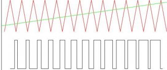
The capacitor charges according to an exponential law. This can be seen in the graph below, where the X axis is time measured in RC, and the Y axis is the voltage across the capacitor as a percentage of the emf source voltage:
The product RC is called the time constant of the circuit. If the resistance of the resistor R is measured in kiloohms (kOhm), and the capacitance of the capacitor C is measured in microfarads (μF), then the product RC will be obtained in milliseconds (ms).
During time t = RC, the capacitor manages to charge to a voltage that is 63% of the voltage of the EMF source; during time t = 3RC, the capacitor will charge up to 95% and at t = 5RC – up to 99%. Those. when the condition t >> RC is met, the voltage on the capacitor will almost reach the EMF value.
Obviously, the lower the resistance of the limiting resistor and the lower the capacitance of the capacitor, the faster this capacitor charges.
1.1 The charge of the capacitor in coulombs is calculated using the formula q=CU:
(k, coulomb), where C is the capacitance of the capacitor, Farad; U is the voltage on the capacitor plates, Volts.
1.2 Relationship between charging current, charge and time I=q/t, I=CU/t:
(A, ampere), where q is the charge of the capacitor, coulombs; t is the time during which the charge is transferred, seconds.
1.3 Energy E in joules (watt*sec) of a charged capacitor can be calculated using the formula E=0.5CU 2:
(J, joule), where C is the capacitance of the capacitor, Farad; U is the voltage on the capacitor plates, Volts.
Note: sometimes it is more convenient to calculate by expressing the capacitance in microfarads (µF) and the voltage in kilovolts (kV).
As can be seen from the formula, the dependence of energy on the capacitance of the capacitor is linear, and on voltage - quadratic. Those. when the voltage on the capacitor increases, for example, by two times, the energy accumulated in it will increase four times.
1.4 Taking into account the fact that combustion in a pulse lamp stops at a certain voltage, approximately equal to 40-70 Volts depending on the type of lamp and its condition, the pulse energy formula takes the form of the difference between the energies of the capacitor at the beginning and end of the discharge:
(J), where C is the capacitance of the capacitor, μF; Un is the initial voltage on the capacitor plates, kiloVolts, Uк is the final voltage on the capacitor plates, kiloVolts.
It is interesting to note that the amount of heat released by the resistor when charging the capacitor does not depend on the resistance of this resistor and is equal to the energy transferred to the capacitor. That is, half of the source energy is converted into the energy of the electric field of the capacitor, and the second half into thermal energy released in the charging circuit in the form of heat losses.
Re: Charging a capacitor
Re: Charging a capacitor
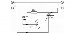
The storage capacitor is charged similarly through a ballast resistor from an alternating voltage source, for example, from a 220 V power supply:
The diode passes the positive half-waves of the source voltage, and they are distributed in the divider formed by resistor R1 and capacitor C1. As the voltage on capacitor C1 increases in small “steps”, the amplitude of the pulses on resistor R1 decreases:
Often, instead of the active resistance of a quenching resistor, the capacitive reactance of a capacitor is used. As is known, a capacitor installed in an alternating current circuit has a reactance that depends on frequency. The capacitance value of the capacitor can be determined by the formula:
or using the Color and Code program:
The reactance of a capacitor, as well as the resistance of a resistor, can dampen excess alternating voltage from the network, and the active power is not released at the reactance of the capacitor, which is a big advantage of a capacitor over a damping resistor.
To obtain low reactance, it is necessary to use high-capacity capacitors. Therefore, electrolytic capacitors are often used as AC ballast resistance. In order for polar capacitors to operate in an alternating current circuit, they are connected according to the following diagram:
The diodes in this circuit create the voltage offset needed for the capacitors to work properly. The total capacitance of such a circuit is equal to the capacitance of series-connected capacitors C1 and C2:
C = (C1 • C2) / (C1+C2)
With equal capacitances C1 = C2, this will be half the capacity of one of the capacitors:
The formula for 3 different capacitors in series looks like this:
C=C1 • C2 • C3/(C2 • C3 + C1 • C3 + C1 • C2)
A corollary from the formulas: if C1=C2, then C=(C1)/2 for two and C=(C1)/3 for three identical capacitors.
Re: Charging a capacitor
Admin, tell us more about fast charging, when the resistor is shunted by a transistor, and as it opens, the total ballast resistance changes from R to 0. In this case, the charging time is 100% per RC, that is, 3-5 times faster.
I want a simple circuit diagram with a minimum of necessary elements.
Re: Charging a capacitor
Re: Charging a capacitor
Re: Charging a capacitor
Since no one among the pros has written about fast charging and shunting a resistor with a transistor, I had to reinvent the wheel in Microcap. Charges the RC 100% exactly -)). Of course, there are many possible options for connecting stabilizing elements, as well as many errors -)
Re: Charging a capacitor
Re: Charging a capacitor
This is Osipoff's circuit for charging IFK-120 in 0.5 seconds
Re: Charging a capacitor
This diagram is not what you drew above. In this circuit, the transistor is in series with the resistor, but in yours it is in parallel.
This circuit is a flash charge interrupter while the capacitors are being discharged to the lamp. It should probably be here: viewtopic.php?f=26&t=101 and the author, if I’m not mistaken, is Waldemar Szymanski. Very similar to his style of drawing diagrams.
Re: Charging a capacitor
The parallel transistor was taken from Marshak’s book “Pulse Light Sources” 1978, p. 352. Compiled quote: “Providing a constant charging current, a variable resistance that varies from Rmax to zero can consist of a resistor Rmax, in parallel with which a transistor is connected as a ballast.”
So I tried to build a theoretical scheme for such inclusion. For practice, it is obvious that a stabilized current source should be built not with positive feedback, but with negative feedback. The simplest option seems to be this:
Re: Charging a capacitor
Re: Charging a capacitor
Due to long-term storage, the properties of the dielectric of the capacitor have deteriorated and it now passes a relatively large current. Sometimes “capacitor training” helps. Connect the flash to an alternating voltage source of 20-30 Volts and keep it under voltage for several days. There is a possibility that the capacitor electrolyte will recover. You can also train, mold stale capacitors by short-term voltage connections: turn on for 3-5 seconds, pause for 1-2 hours. And so on many times until the capacitor capacity is restored and the leakage current is reduced to normal - for K50-17 no more than 1-3 mA.
The power dissipated by the resistor is calculated using the Joule-Lenz formula: P=I 2 R=I*I*R (Watt), - where I is the average value of the current flowing through the resistor (Ampere), R is the resistance value (Ohm) .
Re: Charging a capacitor
Re: Charging a capacitor
Re: Charging a capacitor
Re: Charging a capacitor
They don't think so. And if a resistor is placed BEFORE the diode, will there be 220 V on it?
In your flash circuit, a resistor, diode and capacitor form a series circuit connected to an alternating voltage of 220 V. Consequently, while charging the flash, a pulsating current will flow, the same for all elements of the series circuit. The magnitude of the current is determined by the total resistance of the circuit and the difference between the amplitude voltage of the network and the effective value of the voltage on the capacitor. The more the capacitor is charged, the smaller this difference and the lower the charging current. To calculate the resistor power, you have to calculate the average current during the time the capacitor gains energy. Also, knowing the charging time, capacitance and voltage of the capacitor, you can obtain the average current from the charge transfer formula
Capacitor discharge
After the capacitor is charged, turn off the power source and connect the load R. Since the capacitor is already charged, it itself has turned into a power source. Load R formed a passage between the plates. Negatively charged electrons accumulated on one plate, according to the force of attraction between unlike charges, will move towards positively charged ions on the other plate.
At the moment of connecting R, the voltage on the capacitor is the same as after the end of the transition charging period. The initial current according to Ohm's law will be equal to the voltage on the plates divided by the load resistance.
As soon as current flows in the circuit, the capacitor will begin to discharge. As charge is lost, the voltage will begin to drop. Therefore, the current will also drop. As the voltage and current values decrease, their rate of decline will decrease.
The charging and discharging time of a capacitor depends on two parameters - the capacitance of the capacitor C and the total resistance in the circuit R. The larger the capacitance of the capacitor, the more charge must pass through the circuit, and the more time the charging/discharging process will require (current is defined as the amount of charge, passed along the conductor per unit time). The higher the resistance R, the lower the current. Accordingly, more time will be required for charging.
The product RC (resistance times capacitance) forms the time constant τ (tau). In one τ, the capacitor is charged or discharged by 63%. In five τ the capacitor is charged or discharged completely.
For clarity, let’s substitute the values: a capacitor with a capacity of 20 microfarads, a resistance of 1 kiloohm and a power source of 10V. The charging process will look like this:
Basic formulas for capacity
The basic calculation of a capacitor involves identifying the relationship between the capacitance and the charge held on the element, as well as the voltage on the plates.
C=QVC=QV
C – capacitance, or volume in Farads Q – charge held on the plates in coulombs V – potential difference between the plates in volts
This equation is used to calculate the work required to charge the capacitor and the energy stored in it.
Energy formula
W=∫Q0V dQW=∫0QV dQ
W=∫Q0qC dQW=∫0QqC dQ
W=12CV2
Important! It is necessary to know what effect a capacitor will have on any circuit in which it operates. It not only prevents the passage of the DC component of the signal current, but also affects any AC signal.
Reactance
In a DC circuit, in addition to the battery, there may be a resistor that resists the current in the circuit. The same is true for an alternating current circuit with a charge-storing element. A capacitor with a small plate area allows only a small amount of charge to be stored, and this will prevent current from flowing. A capacitor has a certain reactance, and it depends on its value, as well as on the operating frequency. The higher the frequency, the lower the reactance.
You might be interested in this: Connecting resistors
The actual reactance can be calculated using the formula:
Xc = 1 / (2 pi f C)
Where
Xc – capacitive reactance in Ohms. f – frequency in Hertz. C is the capacitance in Farads.
Current calculation
The reactance of a capacitor, calculated using the above formula, is measured in Ohms. The current flowing in the circuit can then be calculated in the usual way using Ohm's law:
V = I Xc
Main capacitor indicator
Distance between plates
The capacitance of a capacitor is inversely proportional to the distance between the plates. In order to explain the nature of the influence of this factor, it is necessary to recall the mechanics of the interaction of charges in space (electrostatics).
If the capacitor is not in an electrical circuit, then the charged particles located on its plates are influenced by two forces. The first is the repulsive force between like charges of neighboring particles on the same plate. The second is the force of attraction of opposite charges between particles located on opposite plates. It turns out that the closer the plates are to each other, the greater the total force of attraction between charges with the opposite sign, and the more charge can be placed on one plate.
Relative dielectric constant
An equally significant factor influencing the capacitance of a capacitor is the property of the material between the plates as the relative dielectric constant ɛ. This is a dimensionless physical quantity that shows how many times the force of interaction between two free charges in a dielectric is less than in a vacuum.
Materials with a higher dielectric constant allow for greater capacitance. This is explained by the polarization effect - the displacement of the electrons of the dielectric atoms towards the positively charged capacitor plate.
Polarization creates an internal electric field in the dielectric, which weakens the overall potential (voltage) difference of the capacitor. Voltage U prevents the flow of charge Q to the capacitor. Therefore, lowering the voltage helps place more electrical charge on the capacitor.
Below are examples of dielectric constant values for some insulating materials used in capacitors.
- Air – 1.0005
- Paper – from 2.5 to 3.5
- Glass – from 3 to 10
- Mica – from 5 to 7
- Metal oxide powders – from 6 to 20
Processes of charging and discharging capacitors.
We've figured out the device, now let's figure out what happens if we connect a DC source to the capacitor. On circuit diagrams, a capacitor is designated as follows:
So, we have connected the capacitor plates to the poles of the DC source. What will happen?
Free electrons from the first plate of the capacitor
will rush to the positive pole of the source, and therefore there will be a lack of negatively charged particles on the plate and it will become positively charged. At the same time, electrons from the negative pole of the current source will move to the second plate of the capacitor, as a result of which an excess of electrons will appear on it, accordingly, the plate will become negatively charged. Thus, charges of different signs are formed on the plates of the capacitor (this is exactly the case we considered in the first part of the article), which leads to the appearance of an electric field that will create a certain value between the plates of the capacitor. The charging process will continue until this potential difference becomes equal to the voltage of the current source, after which the charging process will end and the movement of electrons through the circuit will stop.
When disconnected from the source, the capacitor can retain accumulated charges for a long time. Accordingly, a charged capacitor is a source of electrical energy, which means that it can release energy into an external circuit. Let's create a simple circuit by simply connecting the capacitor plates to each other:
In this case,
a capacitor discharge current
, and electrons will begin to move from the negatively charged plate to the positive one. As a result, the voltage across the capacitor (the potential difference between the plates) will begin to decrease. This process will end at the moment when the charges of the capacitor plates become equal to each other, accordingly, the electric field between the plates disappears and current stops flowing through the circuit. This is how the capacitor discharges, as a result of which it releases all the accumulated energy into the external circuit.
Source
Rated voltage
The second most important characteristic after capacitance is the maximum rated voltage of the capacitor. This parameter indicates the maximum voltage that the capacitor can withstand. Exceeding this value leads to “punching” of the insulator between the plates and a short circuit. The rated voltage depends on the insulator material and its thickness (the distance between the plates).
It should be noted that when working with alternating voltage, it is the peak value (the highest instantaneous voltage value per period) that needs to be taken into account. For example, if the effective voltage of the power supply is 50V, then its peak value will be over 70V. Accordingly, it is necessary to use a capacitor with a rated voltage greater than 70V. However, in practice, it is recommended to use a capacitor with a voltage rating of at least twice the maximum possible voltage that will be applied to it.