How to measure voltage?
Dim light from lighting fixtures or the refusal of the washing machine to perform its functional duties indicates a possible drop in the supply voltage below normal.
In such cases, it is necessary to measure the voltage, which will determine its compliance with the specified rating of the electrical network. The same procedure is performed when repairing electronic devices, where the voltage drop on radio components and individual sections of the circuit is measured. This procedure is performed quite easily, but without understanding the physics of the process and the specifics of taking measurements, a person risks not only damaging expensive equipment, but also getting electrical injury, so next we will look at the basic principles of measurement.
Devices used
In every home, the electricity meter is in a state of constant measurement of alternating voltage, but it is extremely rare that this data is displayed anywhere. Some of them are connected directly, others through instrument transformers.
For practical purposes, the following can be used to measure voltage levels:
- Voltmeters;
- Multimeters
- Oscilloscopes.
A voltmeter is a device for testing potential differences. In practice, you can find both digital and analog voltmeters, in which the measured voltage is displayed on the display or by deflecting the arrow on the dial, respectively.
Important parameters when choosing both an electronic and a pointer voltmeter are units of measurement (mV, V, kV), operating range and accuracy class. However, the scope of their application is limited and is used, most often, for laboratory research, since for domestic and industrial needs it is impractical to maintain one device for measuring one electrical quantity.
A multimeter or digital tester is a more versatile device that can work with several parameters: electric current, resistance, frequency, temperature, voltage, etc. To measure voltage, the multimeter switches to voltmeter mode, the probes are connected to the appropriate connectors. Structurally, there are both digital and analogue models, in some of them you can switch the measurement range, select the type of current, in other multimeters all these values can be selected automatically.
An oscilloscope is a rather complex instrument for measuring potential differences, since it displays a curve of the measured value on a digital or analog display. In this case, you can stretch or shorten the frequency range to consider the shape of the pulse voltages, pulse duration, rises and dips in the function curve. Therefore, an oscilloscope for measuring voltage is used in electrical circuits and high-precision devices, in the manufacture and testing of radio components, etc. Few people keep an oscilloscope at home due to the high cost and complexity of operations.
Measurement of current, voltage and power in electrical circuits.
⇐ PreviousPage 3 of 3
D/Z. Popov V.S. General electrical engineering with OE.§8.4 - §8.8.
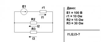
1. To measure voltages and currents in DC electrical circuits, special instruments are used - voltmeters and ammeters.
Fig.1.
Measuring current and voltage with an ammeter and voltmeter.
Voltmeter
designed to measure the potential difference applied to its terminals.
It is connected in parallel to the section of the circuit on which the potential difference is measured. Any voltmeter has some internal resistance RV
.
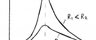
In order for the voltmeter not to introduce a noticeable redistribution of currents when connected to the circuit being measured, its internal resistance must be large compared to the resistance of the section of the circuit to which it is connected. For the circuit shown in Fig.
1 , this condition is written as:
RV
>>
R1
.
This condition means that the current is: IV
=
flowing
through the voltmeter is much less than the current
I
=
that
flows through the tested section of the circuit.
Since there are no external forces acting inside the voltmeter, the potential difference at its terminals coincides, by definition, with the voltage. Therefore, we can say that a voltmeter measures voltage.
Ammeter
designed to measure current in a circuit.
The ammeter is connected in series to an open circuit so that the entire measured current passes through it. The ammeter also has some internal resistance RA
.
Unlike a voltmeter, the internal resistance of an ammeter must be quite small compared to the total resistance of the entire circuit. For the circuit in Fig.
1. The resistance of the ammeter must satisfy the condition
RA
<< (r + R1 + R2),
so that when the ammeter is turned on, the current in the circuit does not change.
Measuring instruments - voltmeters and ammeters - come in two types: pointer (analog) and digital. Digital electrical meters are complex electronic devices. Typically, digital instruments provide higher measurement accuracy.
Ammeter and voltmeter
devices that can be built on the basis of the same device of the magnetoelectric system, which is called a galvanometer:
Fig. 2. Galvanometer.
Any galvanometer has a wire coil with a resistance RГ
. If an additional resistance is connected in series to the galvanometer, then it can be used as a voltmeter by connecting it, along with the additional resistance, in parallel to a section of the circuit:
Fig. 3. Connecting additional resistance to the galvanometer.
Rd = R
g(
n – 1
), where
n
=, is the ratio of the voltage that needs to be measured to the voltage that falls on the galvanometer coil.
In accordance with the laws of series connection and Ohm's law for a section of the circuit we have:
I
d =
I
g,
= , = ,
U
‒
U
g =
R
d , ‒ 1 = ,
n
‒ 1 = ,
Rd = R
g(
n – 1
).
If a resistance (shunt) is connected in parallel to the galvanometer, then it can be used as an ammeter by connecting it, together with the shunt, in parallel to a section of the circuit:
Fig. 4. Connecting the shunt to the galvanometer.
U
w =
U
g,
I
w⋅
R
w=
I
g ⋅
R
g, (
I
‒
I
g )⋅
R
w=
I
g ⋅
R
g, ( ‒1)⋅
R
w=
I
g ⋅
R
g,
R
w = , where
n
= , is the ratio of the current that needs to be measured to the current that comes through the galvanometer coil.
.
2. Power measurement.
Power in an electrical circuit can be measured using an ammeter and a voltmeter.
Knowing the ammeter and voltmeter readings using the formula:
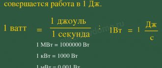
P = U∙I —
determine the power in the electrical circuit.
The power in an electrical circuit can be determined using a wattmeter of an electrodynamic system.
.
Fig. 6. Coil connection diagram Fig. 7. Coil connection diagram
electrodynamic wattmeter. electrodynamic wattmeter.
The output coil (its output is designated *), which is connected in series to the current source (generator), is called a current coil.
The coil that is connected in parallel with the load is called a voltage coil. One of the terminals of this coil is designated *and is connected to the terminal of the current coil, indicated by an asterisk*. The scale of such a device is graduated in watts (W).
⇐ Previous3
Recommended pages:
Use the site search:
Network voltage measurement
In order to correctly measure voltage, it is necessary to clearly understand the principle and object of study. Therefore, it should be noted that voltage is an electrical quantity that shows the difference in charge between two electrical points. For example, if at one point the charge is +35 V, and at another +310 V, then the difference between these points will be 310 - 35 = 275 V, this will be the voltage. Accordingly, voltage measurements can only be made relative to something, so two points are used at once.
Rice. 1. Voltage measurement circuit
If we talk about the voltage drop at any object or section of the circuit, then the voltage measurement is carried out relative to the ends of the device or circuit, connection points, etc. It is important to take into account that a digital voltmeter or multimeter in measurement mode is considered to have infinite resistance or an open circuit.
A voltage drop is possible only if current flows, so connecting voltmeters in series with the object being measured is unacceptable, since current will stop flowing through it. An analogue or electronic voltmeter must only be connected in parallel with the signal being measured.
From a practical point of view, it should be noted that analog models of measuring instruments have an input impedance of 10 - 20 kOhm, and modern multimeters can boast 1 MOhm. Since leakage current may flow through the resistance at the input of the measuring device, this voltage divider will cause a decrease in measurement accuracy. Therefore, the closer the input resistance is to infinity, the more accurate the device you use.
It is important to note that measurements are taken under voltage, which poses a risk of electric shock. Therefore, it is important to take basic precautions. Next, we will consider the procedure for performing measurements for direct and alternating voltage.
Direct current
Rice. 2. DC voltage measurement
For a DC circuit, let's look at how to measure voltage using a digital multimeter. For this:
- Set the multimeter switch to constant voltage. On the panel it is indicated by the Latin letter V with the “=” sign, “+ and –” signs, and can also be denoted by the abbreviation DC.
- Select the desired measurement limit, which will be as close as possible to the expected nominal value, but higher than what is being measured.
- Install the probes into the appropriate connectors - black to the COM pin, red to the V pin.
- Apply the multimeter probes to two points at once - red to positive, black to negative. If you do not know the position of the potentials in advance, and the device reading is negative, you just need to change the polarity of the connection.
On the display you will see the voltmeter readings; if the value is too low, switch the knob to a lower measurement range. When applying the probes, create a good force to avoid high contact resistance, otherwise they will introduce a noticeable measurement error.
Alternating current
Rice. 3. AC voltage measurement
In the AC circuit of a household circuit, it is important to take into account its danger due to the rating of 220/380 V. Therefore, if it is impossible to connect the multimeter directly during operation, its connection should be carried out with the voltage turned off using “crocodiles”.
Otherwise the measurement process is identical:
- Switch the multimeter handle to the AC voltage position. On the panel it is indicated as V with the icon “
" or the abbreviation AC.
- Use the handle to set the division to the desired limit based on the principle of the nearest higher potential relative to the measured value.
- Connect the probes to the corresponding pins: black to the COM pin, red to the V pin.
- Connect the measuring device to the desired device, note that the polarity of the probes does not matter here.
The display will show you the current value of the potential difference, which is the main value for all calculations. But, in addition to this, there is also an amplitude value that is √2 times or 1.41 times greater than the effective value.
Measurement of current, voltage, resistance
Current measurement
To measure current in a circuit, ammeters are used, connected in series to the circuit where the current value is determined.
To ensure that the current in the circuit does not change when the ammeter is turned on, the resistance of its winding must be made very small. To do this, the ammeter winding is made of a small number of turns of thick wire. To expand the ammeter's measurement limits, shunts are used. Shunts are manganin plates or rods soldered into copper or brass tips. The shunt is connected in series. An ammeter is switched on in parallel. The current I in circuit A branches in inverse proportion to the resistance of the ammeter winding ra and the shunt rsh: Ia/Ish= rsh/ra, and Ish=I- Ia, from which the shunt resistance will be rsh=(Iara)/(I- Ia). Let us denote the ratio of current I to current Ia by n (the number n is sometimes called the shunt coefficient). Then the expression for rш can be written as follows: rш = rа/(n-1). For currents up to 100 A, shunts are placed inside the device (internal shunts). For high currents, shunts are made external and connected to ammeters using wires whose resistance is precisely adjusted, since otherwise the distribution of currents will be different and the measurement will be incorrect. There are universal shunts for several measurement limits. Devices that constantly operate with their individual shunt are calibrated taking into account the shunt, which is indicated on the device scale. Calibrated shunts are also often used. Such a shunt can be connected to any device designed for the same voltage drop as this shunt. Typically, shunts are installed only to devices of the magnetoelectric system for measurements in DC circuits. To expand the measurement limits of ammeters in alternating current circuits, current transformers are used. Voltage measurement
Voltmeters are used to measure voltage. Voltmeters are connected in parallel to the section of the circuit where the voltage needs to be measured. To ensure that the device does not consume high current and does not affect the voltage of the circuit, its winding must have a high resistance. The greater the internal resistance of the voltmeter, the more accurately it will measure the voltage. For this purpose, the voltmeter winding is made of a large number of turns of thin wire. To expand the measurement limits of voltmeters, additional resistances are used, connected in series with the voltmeters. In this case, the network voltage is distributed between the voltmeter and the additional resistance. The value of the additional resistance must be selected in such a way that in the circuit with increased voltage the same current passes through the voltmeter winding as at the rated voltage. The current for which the device winding is designed is Iв=U/rв. In a circuit with a voltage n times greater, the voltmeter current with additional resistance r should remain the same: Iv=nU/(rv+ r) or U/rv=nU/(rv+ r), hence the value of the additional resistance is r= rv(n -1). Additional resistances are made from manganin wire wound on a getinax or porcelain frame and placed inside the device or separately from it. To measure high AC voltages, voltage measuring transformers are used.
Power factor measurement
The value of the power factor in single-phase alternating current networks can be determined from the readings of a voltmeter, ammeter and wattmeter according to the formula cos φ=P/UI. Using the same devices, the power factor in three-phase current networks with a uniform load can be determined by the formula cos φ=P/UI√3, where U and I are linear voltage and current, and φ is the shift angle between phase voltage and current. The average value of the power factor cos φav for a certain period of time can be determined from the readings of active and reactive energy meters for the same time according to the formula cos φav = Aa/√(Aa2+ Ap2), where Aa is active energy; Ap - reactive energy. In practice, the instantaneous value of the power factor is determined using special devices - phase meters.
Measuring resistance with a megger
Meggers are used to measure the resistance of individual parts of electrical installations in relation to the “ground” and in relation to each other. According to the rules, the insulation resistance of the wires must be at least 1000 ohms for each volt of operating voltage. So, for example, for a network with an operating voltage of 220 V, the insulation resistance must be at least 220,000 Ohms, or 0.22 MOhm. Insulation resistance should be measured with a voltage that is, if possible, equal to the operating voltage, and in any case with a voltage not less than 100 V. Megger meters, the readings of which depend on the voltage, consist of a voltage source and a meter. If an adjustable resistance r is connected in series to the circuit, then the readings of the meter (voltmeter) will depend on the value of this resistance (at a constant circuit voltage). At r=0 the voltmeter reading will be small, at r=∞ the voltmeter will show zero. By including various resistances, you can calibrate the meter scale directly in ohms (kilo-ohms, mega-ohms). In the future, such a device can be used to measure resistance if you use an energy source with a voltage equal to the calibration voltage.
Real voltage measurement examples
The simplest example of measuring voltage at home is a AA battery. In it you need to attach the black probe to the “–” terminal and the red one to the “+” terminal, set the switch position to 2 V DC voltage.
Rice. 4. Example of measuring voltage on a battery
If the readings for a 1.5 V battery are in the range from 1.6 to 1.2 V, then such a power source is considered suitable for all equipment; if the values reduce to 1 - 0.7 V, pulsed devices will be started from the battery, for example, a watch. If the voltmeter shows 0.6 V or less, the discharge has reached a critical value.
When measuring the potential difference in a household network, you should touch the contacts of the socket with the probes. Since the insulated part of the probe has a restrictive ring behind which there is a long rod, you can safely reach into the outlet without the risk of touching live parts. Deviations from the nominal value by 10% are considered acceptable, that is, from 198 to 142 V.
You can also measure the potential difference at the output of a car battery or at another element of the electrical wiring circuit. To do this, the black probe of the multimeter is installed on the “–” terminal of the battery, and the red one on the “+” terminal.
If the battery is charged, then the voltmeter readings should be in the range from 12 to 14 V, but there are models with a large spread. This measurement allows you to diagnose various causes of problems.
Current, voltage and power measurements
Current measurement . Ammeters are used to measure current. The ammeter is connected to the circuit in such a way that the entire measured current passes through it, i.e. sequentially. Therefore, its resistance should be small compared to the resistance of the circuit.
To measure direct current, devices of the magnetoelectric system are used, less often devices of the electromagnetic system. To measure alternating current with a frequency of 50 Hz, electromagnetic system devices are mainly used. The resistance of these devices ranges from a fraction of an ohm to several ohms.
To expand the measurement limits of ammeters in DC circuits, shunts are used. Their resistance is calculated using the formula:
where I
an is the rated current value of the ammeter;
R
a is the internal resistance of the ammeter;
I
w is the current passing through the shunt.
To expand the measurement limits of ammeters in alternating current circuits, measuring current transformers are used.
Voltage measurement. Voltmeters are used to measure voltage.
Voltmeters are connected in parallel to the section of the electrical circuit on which the voltage is measured. The voltmeter must have a high resistance compared to the resistance of the corresponding section of the circuit. In DC circuits, voltmeters of the magnetoelectric system are used, but usually with additional resistance.
To expand the measurement limits of voltmeters in DC circuits up to 4500 V, additional resistors (resistances) are used. Their resistance is determined by the formula:
where U
n is the rated voltage of the device;
U
max - maximum measured voltage;
RV
is the resistance of the voltmeter.
In alternating current circuits, voltmeters of the electromagnetic and electrodynamic systems are used.
Power measurement. The power in an electrical circuit of sinusoidal current is determined by the formula:
P=UI
cos(
Ð
)
,
where U
and
I
are the effective values of voltage and current;
j = Ð
- angle of difference between initial voltage and current (phase angle).
To measure power in electrical circuits, it is necessary to measure voltage, current and phase angle. For this purpose, a device is used - a wattmeter with two coils. These are devices of electrodynamic and ferrodynamic measuring systems. The voltage coil is connected in parallel to a section of the circuit, like a voltmeter; its terminals on the front side of the wattmeter are marked with the letter U.
The current coil is connected to the circuit in series, like an ammeter, its terminals are marked with the letter
I
(Figure 1.4.).
Figure 1.4 - Wattmeter connection diagram
On the wattmeter, the beginning of the current coil and the voltage coil are marked with asterisks; these are generator terminals. When measuring active power, these clamps are switched on from the energy source side. A phase meter, a device designed to measure the phase shift angle j, has the same features and is also included in the network. It allows you to directly determine the angle j and cos j on the scale.
The division price of a multi-range wattmeter is determined by the formula:
where U
p
, I
p—the limit values of voltage and current indicated on the corresponding terminals of the device;
n
is the number of scale divisions.
Active power, measured by a wattmeter,
where W
meas - the number of scale divisions indicated by the arrow of the device.
In the same way, the division price of an ammeter and voltmeter is determined if the instrument scale is not graduated in units of measurement.
Your opinion is important to us! Was the published material useful? Yes | No
Source
Current and voltage measurement
DC measurements
Direct current and voltage measurements are made using instruments of magnetoelectric, electromagnetic, electrodynamic systems; voltage is also measured by electrostatic and electronic voltmeters. In addition, DC compensators are used for more accurate measurements.
Magnetoelectric measuring mechanisms are directly micro- and milliammeters or millivoltmeters, and in combination with shunts and additional resistances - ammeters and voltmeters, respectively.
To measure and detect small currents (10-11 - 10-5 A) and voltages (less than 10-4 V), galvanometers are used - highly sensitive measuring mechanisms, usually of a magnetoelectric system. Unlike instruments whose scales are graduated in measured quantities, galvanometers have an unnamed scale, the division value of which is indicated in the passport data of the device or is determined experimentally.
Measuring direct currents and voltages can be done using ammeters and voltmeters of electromagnetic and electrodynamic systems. They are mainly used for measurements in alternating current circuits.
Electrostatic measuring mechanisms are electrostatic voltmeters because they can directly measure voltage. The range of voltages they measure ranges from tens of volts to hundreds of kilovolts. To measure voltages up to 3 kV, measuring mechanisms with varying activity of the electrode surface are used. Voltmeters are manufactured as single-limit and multi-limit, portable (up to 30 kV) and stationary (for measuring high voltages, over 30 kV).
The accuracy class of modern electrostatic voltmeters reaches 0.1 and even 0.05 (S-71), however, devices of classes 1.5 are most often manufactured; 2 and 2.5. To reduce the influence of external electrostatic fields, electrostatic shielding is used. The measurement limits are expanded using resistor voltage dividers.
The main advantages of electrostatic voltmeters are: very low inherent power consumption (high input resistance, 1010 Ohms), the ability to measure direct and alternating voltages, and the ability to directly measure high voltages. Disadvantages include low sensitivity and uneven scale.
Measurement of direct voltages from fractions of a volt to several kilovolts can be carried out using electronic voltmeters, which contain a measuring mechanism and a DC tube or transistor amplifier. There are several types of electronic DC voltmeters, but they are all characterized by the block diagram shown in Figure 6.1. 6.1.
Rice.
6.1. Block diagram of an electronic constant voltage voltmeter: a) with dial reading; b) with digital readout
The input device (voltage divider), to which voltage UX is applied, allows you to change the measurement limits and provides a high input impedance of the device.
A magnetoelectric microammeter with a measurement range of 50–500 μA is usually used as a measuring mechanism.
DC amplifiers are designed to increase the sensitivity of the device, increasing the power of the measured signal to a level that ensures the required deviation of the measuring mechanism pointer. The amplifiers have high input and low output impedance. This ensures matching of the input resistance of the voltmeter (10 - 20 MOhm) with the low internal resistance of the microammeter. Most often, amplifiers are made in the form of bridge circuits with feedback.
Electronic voltmeters with pointer reading have the following features: high input resistance and, therefore, low power consumption from the measurement object; high sensitivity with a large measuring range; ability to withstand overloads; relatively low measurement speed (due to the inertia of the magnetoelectric measuring mechanism); need for power (from mains or battery); large errors (the main reduced error is 2 - 3%).
Nowadays, of course, digital voltmeters have become more widespread - devices with a digital reading device and an analog-to-digital converter in which voltage (or other physical quantities; frequency, phase shift, etc.) are automatically converted into a digital code. Such devices have a number of advantages over pointer devices: they have a wide range of measured voltages (from 1 mV to 1000 V), speed, and allow measurements with small errors (0.01 - 0.005), since the operating principle of most devices is based on the comparison method, and Digital reading eliminates reading errors. Digital voltmeters also allow you to enter measurement data directly into computers, which allows you to further process the received data more quickly.
Disadvantages include the complexity of the device, less reliability and high cost.
There are various principles for constructing digital DC voltmeters:
- According to the type of elements used in the circuits, they are divided into:
- electromechanical;
- combined.
electronic;
- spatial coding;
intermediate conversion (to time interval, frequency, phase, etc.);
A generalized block diagram of an electronic digital voltmeter is presented in Figure 6.2. 6.2.
Rice.
6.2. Generalized structure diagram of an electronic digital voltmeter
The input device is a high-resistance resistance (about 10 MOhm) or a cathode (emitter) follower with a calibrated divider.
A comparison device (null organ) is used to compare the measured and reference voltages.
Control devices consist of a pulse generator that sets measurement cycles and controls the operation of logic circuits.
The voltage-to-code converter creates a reference voltage UOBR, which is supplied to the comparing device.
An electronic key is a device that turns on or switches the output voltage under the influence of one or more input voltages, called control voltages.
Electronic meters read the measured voltage in a digital code (usually in a binary system).
§ 70. Measurement of alternating current and voltage
Inclusion of an ammeter in the circuit of the measured alternating current in series with the load is equivalent to inclusion in the circuit of its inductance and capacitances (capacitance between each of the terminals of the device and the housing, as well as between the terminals of the device). Typically these capacitances and inductances are small and only have an effect at high frequencies. With a significant increase in frequency, inductive reactance increases, capacitive reactance decreases, and some of the current bypasses the device, which causes a frequency error.
Therefore, each device can be used in a certain frequency range, in which the frequency error does not exceed that specified in the passport. At higher frequencies the measurement error will be greater than normal.
Including a device in a circuit changes the resistance and setting of the circuit. To avoid resonance phenomena caused by the device’s own inductances and capacitances, at high frequencies it is necessary to use devices with small inductances and capacitances.
For measurements in alternating current circuits, rectifier detectors are used, which are a combination of a magnetoelectric indicator and a diode. The measured alternating voltage is rectified by a diode, and a direct current flows in the indicator circuit, causing the needle to deflect. Half-wave and full-wave circuits for connecting diodes and a magnetoelectric indicator are used, most often full-wave bridge circuits; they are used for measurements at low frequencies.
Measurement of current, voltage, power educational and methodological material on the topic
Measurement of current, voltage, power.
MEASUREMENT OF CURRENT, VOLTAGE, POWER IN ELECTRICAL CIRCUITS
Voltage and current in DC circuits are measured using magnetoelectric system devices. In order for the needle of such devices to deviate in the desired direction, the current from the positive pole of the power source must flow to the “+” terminal of the ammeter.
The simplest way to measure direct current is to directly connect the ammeter directly. In this case, three conditions must be met:
- the ammeter's measurement limit must be greater than or equal to the maximum operating current of the circuit;
- The test voltage of the ammeter must be greater than the mains voltage Ua > Uс,
- The ammeter resistance must be greater than the receiver resistance RA > Rnp.
To expand the limits of direct current measurement, measuring shunts are used, which are characterized by the rated primary current Ish, the voltage drop Um created between their measuring terminals at this current, and the accuracy class. Standard current measuring shunts are designed for voltage drops of 45 and 75 mV.
The lower the shunt's rated current, the greater its internal resistance. When connecting several devices parallel to the shunt, an error may occur that exceeds the permissible value for its accuracy class. Therefore, when shunt currents are several tens of amperes, one measuring device is connected to it.
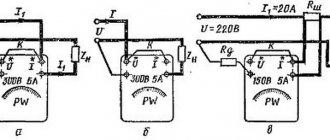
Voltage in DC circuits can be measured by instruments of various systems. When using PV voltmeters of a magnetoelectric system, the switching polarity should be observed (Fig. 1, a). To expand the measurement limits of voltmeters, additional resistors are used (Fig. 1, b). In this case, the measurement limit is:
Fig 1. Schemes for connecting voltmeters in a DC circuit: a - direct connection, b - with an additional resistor where UPVx is the extended limit of the voltmeter; RD is the resistance of the additional resistor; K is a coefficient showing how many times the voltage measurement limit of the device increases when using an additional resistor. Various shunts and additional resistors are available to expand the measurement limits of DC instruments. Alternating voltage and current can be measured with instruments of any system, with the exception of magnetoelectric. When measuring large currents in low-voltage installations, as well as voltages and currents in high-voltage installations, electromagnetic system devices are used, connected through special current and voltage transformers. In the practice of adjustment work, various measuring transformers are used, but it should be remembered that they introduce additional error into the measurement result. To ensure that the error does not exceed the permissible one, determined by the accuracy class of the instrument transformer used, its secondary winding must be connected to the rated resistance. The nominal resistance of the secondary winding of the current transformer circuit is the greatest, and the voltage transformer is the least resistance to which this winding can be turned on without exceeding the permissible error. The circuits for connecting voltmeters with additional resistors in DC circuits and single-phase AC networks are the same (Fig. 1.6). Connection circuits for ammeters and voltmeters when using instrument transformers are shown in Fig. 2, a, b. Fig. 2. Connection diagrams for AC measuring instruments: a - with a current transformer, b - with a voltage transformer. In a single-phase alternating current circuit, power is measured directly using an electrodynamic wattmeter or indirectly using an ammeter and voltmeter. The device connection diagram is shown in Fig. 3.
Knowing the voltage U applied to the load, the current I passing through it, and the shift angle ϕ between current and voltage, it is possible to determine the active, reactive and total power: P = UI cosϕ; Q = UI sinϕ; S = UI. The angle ϕ or cosϕ is determined using a phase meter. In the absence of a phase meter, the total power is found from the readings of a voltmeter and ammeter: S = UI. Using a wattmeter, active power is measured, hence: cosϕ = P/S; ϕ = arccosP/S; Q = UI sinϕ. When connecting a voltmeter to the circuit being measured, take into account the polarity of its terminals (the beginning of the current winding and the voltage winding).
Rice. 3. Connection diagram of devices for measuring power: Rн - load resistor, Rд - additional resistor to the voltage winding of the wattmeter.
With a uniform load, the power in a three-phase network can be measured with one wattmeter. Measurement circuits for three-phase four-wire and three-wire networks are shown in Fig. 4, a, b. When the network zero point is inaccessible, an artificial zero point is created, and the resistances must be equal: Rda = Rdd = Rds. Power is determined by summing the readings of all three wattmeters.
Rice. 4. Circuits for connecting wattmeters for measuring the active power of three-phase current: a - direct, b - with an additional resistor.
Rice. 5. Circuits for connecting two wattmeters to measure the power of three-phase current.
To measure the power of a three-phase current circuit, two wattmeters are most often used for both symmetrical and asymmetrical phase loading. Three equivalent options for connecting wattmeters when measuring active power are shown in Fig. 15.
Active power is determined as the sum of the readings of two wattmeters. Reactive power in a three-phase circuit with uniform loading of all three phases can be measured using one wattmeter (Fig. 6, a). To obtain the total reactive power, the readings of one wattmeter are multiplied by 3. With a uniform and uneven load, the reactive power in a three- and four-wire network is determined using three wattmeters (Fig. 6.6).
Fig. 6. Schemes for measuring reactive power in a three-phase network: a - using one wattmeter, b - using three wattmeters. To measure power in three-phase circuits with a symmetrical load, wattmeter current clamps are used (Fig. 7). Most often they are used to determine the load of three-phase motors M with voltages of 380 and 660 V with an accessible neutral (Fig. 7). During the measurement process, one of the supply wires is covered with pliers, and the voltage clamp marked with an asterisk is connected to this wire, and the “220 V” clamp (in a 660 V circuit, the “380 V” clamp) is connected to the neutral of the stator winding. If the device readings are negative, the pliers should be turned 180° when covering the wire or the voltage circuit wires should be swapped.
Rice. 7. Measuring the power of a three-phase motor using a wattmeter clamp meter. In alternating current networks, metering of generated and consumed electricity is carried out using induction system meters, which are manufactured in single- and three-phase versions. The latter come in two modifications - for a three- and four-wire network. To account for the consumption of active and reactive energy, special meters are produced. To measure active energy in three-phase networks, meters SAZ, SA4, SA4U are used, reactive energy - SRZ, SR4, SR4U (the number 3 in the meter type designation indicates that it is intended for a three-wire network, 4 for a four-wire network). SA4U and SR4U meters are produced only for connection with current and voltage measuring transformers; other types of meters are available for direct connection and with transformers.
To account for energy in single-phase current circuits, CO meters are used.
Active energy meters are manufactured in accuracy classes 1.0; 2.0; 2.5, reactive energy meters—2.0; 2.5; 4.0. The accuracy class of meters and instrument transformers intended for commercial and technical metering circuits must comply with the requirements of the PUE. Diagrams of internal connections of three-phase meters are shown in Fig. 8, a - d. The indices G and H indicate the terminals of the meter windings, connected to the supply side of the circuit and the load, respectively. Fig. 8. Schemes of internal connections of three-phase meters: a - active energy of the SAZ and SAZU type, b - reactive energy of the SRZ and SRZU type, c - active energy of the SA4 and SA4U type, d - reactive energy of the SR4 and SR4U type with an additional series winding, e - reactive energy type SR4 I676 and SR4U-I676, 1 – 10 – terminal numbers.
Connection diagrams for three-wire active energy meters of the SAZ and SAZU types and reactive energy meters of the type SRZ and SRZU are shown in Fig. 9, a - c, and the connection diagrams for four-wire active energy meters SA4 and SA4U and reactive energy meters SR4 and SR4U are in Fig. 10, a - d.
Rice. 9. Connection diagrams for an active energy meter of the SAZ and SAZU type and a reactive energy meter of the SRZ, SRZU type: a - direct connection, b - with current transformers, c - with current and voltage transformers. Fig. 10. Connection diagrams for active energy meters of types SA4 and SA4U and reactive energy meters of types SR4, SR4U, SR4-I676 and SR4U-I676: a - direct connection, b - with current transformers, c - with current and voltage transformers in a three-wire circuit, d - with current and voltage transformers and a four-wire circuit (in reactive meters there are no clamps 10).
Sometimes during commissioning work, meters are used to measure power. Let's consider an example of determining the power consumed by a motor using a three-phase meter. We count the number of revolutions of the disk over a period of time t (usually 20-40 s, counted with a stopwatch, is enough); The engine load should not change during this period. If the meter plate, for example SAZU type, indicates 1 kW. h = n revolutions of the disk, then power, kW: where Ktt and Ktn are the transformation ratios of current and voltage transformers, respectively.