The most common types of electrical measurements are current and voltage measurements.
Depending on the type of current (voltage), its magnitude, frequency, shape, required measurement accuracy, resistance of the circuit in which the measurement is made, various types of devices are used.
When measuring the current in a section of a circuit with resistance R, an ammeter
(Figure 7a). Then the current flowing through the measuring device and the section with resistance R will be the same.
Voltmeter
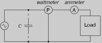
is connected in parallel to a section of the circuit with resistance R, the voltage across which is measured (Fig. 7b). When connected in parallel, the voltage on the measuring device and the circuit section R is the same. Connecting a measuring device to an electrical circuit affects the operating mode of this circuit, which leads to errors in measurements.
Rice. 7. Connecting an ammeter (a) and a voltmeter (b)
with
resistance r
a
increases the total resistance of the circuit section to the value
R
+
r a
, which is greater than
R. As a result, the current will decrease. In order for the change in current to be insignificant, it is necessary that the following condition be met: r and
R.
When a voltmeter with resistance r
v
, the total resistance becomes equal to
,
which is less than R
.
The measured voltage will be underestimated. To ensure that the voltmeter does not introduce large distortions into the operating mode of the circuit, the following condition must be met
: r v
>>
R.
Shunts to ammeter
The current that causes the moving part of the device to deflect over the entire scale is called the total deflection current I
0
.
If using an ammeter it is necessary to measure the current I
greater than
I 0
, an additional resistance
R w
, called a shunt, is connected to it in parallel (Fig.
Rice. 8. Connecting the shunt to the ammeter.
The measured current is branched and only part of it passes through the measuring device. This is how the ammeter's measurement limit is expanded. According to Kirchhoff’s first rule, current values are related by the relation:
, (12)
where I
– the strength of the measured current,
I p
– the strength of the current flowing through the measuring mechanism (frame) of the device,
I w
– the strength of the current flowing through the shunt.
According to Kirchhoff's second rule, we have:
, (13)
where r
is the resistance of the ammeter frame,
R w
is the resistance of the shunt. From (12) and (13) it follows that
. (14)
Expression (14) allows us to determine R
w
at which the deviation of the meter needle to the full scale will correspond to the required limit for measuring the current strength
I pr
.
In other words, when I
=
I current,
the current through the ammeter
I r
will be equal to the total deviation current:
I r
=
I 0
. In this case, expression (14) takes the form:
. (15)
In practice, the shunt coefficient (or stretching coefficient of the measurement limit) n
for a given value
I pr
, which is equal to
(16)
Then expression (15) takes the form:
. (17)
With this shunt, the ammeter division price will also increase by n
once.
How to measure charger current with a multimeter
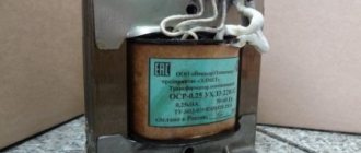
The battery charger converts alternating current from the network into direct current using a transformer, rectifier and voltage stabilizer. For car owners, starting and charging devices are produced - ROMs - which combine the functions of charging the battery and starting the engine when the battery is dead. In this case, there may be no charge at all, or within a few minutes a partial charge is created, which is necessary for the motor to start operating.
Some charger models do not have a charge indication, so there is a problem with determining the amperage. You can easily check the current strength with a regular multimeter:
- The battery must be removed from the car and connected to the charger.
- On the multimeter, set the scale to 10 A, and insert the red probe into the connector, also at 10 A.
- Connect the “plus” of the charger to the positive pole of the battery.
- Connect the “minus” of the charger with a black probe to the base of the multimeter (COM socket).
- Connect the red probe to the second terminal of the battery.
Additional resistance to the voltmeter
The measurement limit of a voltmeter depends on the current strength of the total deflection of the moving part of the device I
o
and its internal resistance
r
. To expand the measurement limits of the voltmeter, an additional resistance is connected in series with the measuring mechanism of the device
(Figure 9).
The voltage on the measuring mechanism U
p
is less than the measured voltage
U
and is related to it by the relation:
,
Where
– voltage across additional resistance. Current flows through such a circuit
From the last formula it follows that
(18)
Rice. 9. Connecting additional resistance to the voltmeter.
From (18) it is possible to determine the value at which the needle deflects to the full scale ( I
=
I 0
) will correspond to the required voltage measurement limit
U
=
U pr
. (19)
A set of additional resistances allows you to create a multi-limit voltmeter. Additional resistances external to the device are also used.
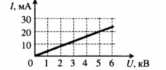
Many people remember Ohm's law from school physics : the current strength in a circuit is directly proportional to the voltage and inversely proportional to the resistance.
CURRENT STRENGTH
is a quantitative characteristic of electric current - it is a physical quantity equal to the amount of electricity flowing through the cross-section of a conductor per unit time.
Measured in amperes.
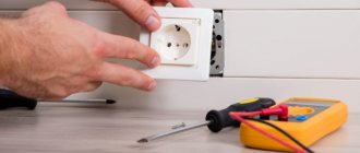
For electrical wiring in an apartment, the current strength plays a huge role, because based on the maximum possible value for a separate line coming from the electrical panel, the cross-section of the conductor and the value of the maximum current of the circuit breaker that protects the electrical cable from damage in the event of a short circuit or overload currents depend.
Therefore, if the cross-section and circuit breaker are not chosen correctly, it will simply be knocked out, and replacing it with a more powerful one will simply not work.
For example, the most common wires and cables in electrical wiring with a cross-section of 1.5 square millimeters are made of copper or 2.5 square millimeters of aluminum. They are designed for a maximum current of 16 Amps or a power connection of no more than 3 and a half kilowatts. If you connect powerful electrical consumers exceeding these limits, then you cannot simply replace the circuit breaker with a 25 A one - the electrical wiring will not withstand it and you will have to transfer a copper cable with a cross-section of 2.5 sq. m from the switchboard. mm, which is designed for a maximum current of 25 A.
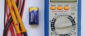
External structure and functions
The appearance of analog and digital multimeters differs slightly. To a large extent, these differences lie in the separation of the display screens.
For an analog device, the display contains a measurement scale, graduated for different operating modes, and an arrow.
The digital version has an LCD screen that displays measurement readings in any operating mode of the device. For different models, the screen can be monochrome (2 colors) or color. The minimum number of reading digits is 4.
Increasing the number of digits does not mean increasing accuracy. Accuracy, as an error, is indicated in the characteristics of the device. The display shows the selected mode, battery charge, and a minus sign for negative values.
Below the reading window there is a multi-position switch, the position of which determines the types and limits of measurements.
- To measure alternating voltage, turn the knob to the ACV (alternating current voltage) position.
- In DCA mode (direct current amperage), the device allows you to measure direct current.
- The switch in the DCV position will allow you to determine the constant voltage indicator.
- Pointer on the “Ω” icon - the device is ready to measure resistance, i.e. works like an ohmmeter.
The device comes with two probes; black and red. Three sockets on the front panel allow you to connect them to the device for taking measurements.
The black wire (also called “ground”, “minus”, “common”) is connected to the device through the lower (if vertical) socket, marked “minus” or “COM”. The negative wire is used in all modes and for any permissible values. The red wire should be inserted into the socket marked with a “+” sign. This socket is designed for measurements in all modes, in the range up to 10A.
The third socket, located on the top or left, is used to measure large DC currents (more than 10A).
The maximum permissible measurement value can be indicated on the front panel, for example, “MAX 600V”.
The device is powered by a Krona battery.
Structure of an electronic multimeter
The appearance of the device has changed since its invention. The need to use several instruments and the inconvenience of carrying separate meters led to the appearance of the first pocket avometer in 1920.
The ubiquitous modern digital multifunction devices have many modifications.
The internal content changed with the development of technology.
A modern digital universal tester is based on a controller with an analog-to-digital converter module. The microcircuit located in the housing includes a special unit that evaluates the incoming voltage.
The operating principle is based on comparison of two signals: input and reference.
The presence of built-in resistors allows you to measure current by voltage drop.
The voltage is measured via a direct connection to the network.
When current is applied to a resistor, the resistance is measured.
Changing the measurement limits is possible thanks to resistor dividers.
Switch position
- The appliance is turned off if the switch is in the OFF position.
- To measure alternating voltage, use the mode indicated on the panel by the sign ACV or “~”. Typically, this mode provides 2 values - 200 and 600 or 200V and 750V.
- Range of available DC current values: 200 µA, 2000 µA, 20 mA, 200 mA, located under the DCA or “=” sign.
- hFE – mode for measuring the current gain of the transistor.
- You can measure the resistance value (“Ω” mode) in the range from 200 Ohm to 2000 kOhm.
- DC voltage is available for measurements in values of 200 mV, 2000 mV, 20 V, 200 V, 600 V. The range is indicated as “DCV” on the panel.
Measurements
With an average multimeter you can measure:
- Mains voltage.
- Battery voltage.
- Current strength.
- Resistance.
- Current frequency.
- Temperature.
- Capacitor capacity.
The ability to test diodes and transistors (ringing) is another opportunity that a multifunctional measuring device provides.
IMPORTANT. Before starting measurements, it is necessary to turn the central knob to the maximum value of the measured value. This will avoid damage to the device and obtain extremely accurate measurement results.
Compliance with the operating rules will ensure long-term operation of the combined electrical measuring instrument and error-free determination of readings:
- You should not measure high currents and voltages with a household multimeter - it may break down.
- It is necessary to change the power source in a timely manner.
- Before starting measurements, you must make sure that the selected measurement mode corresponds to the upcoming actions.
- After completing the work, it is important to turn off the device.
- Measurements should not be taken in conditions of high humidity.
IMPORTANT. Analog devices are not used to measure alternating voltages and currents, since they require connection to the network in accordance with polarity. Digital multimeters solve this problem by automatically detecting polarity.
You should choose a multifunction meter based on your needs. The set of functions and characteristics, including screen backlighting and measurement accuracy, will determine the model and cost of the device. For household needs, you can choose a multimeter with a limited number of functions. For an auto mechanic and radio designer, a professional high-precision device is more suitable.
Units for measuring the power of electric current.
In addition to Amperes, we often come across the concept of electric current power. This value shows the work done by the current per unit time.
Power is equal to the ratio of the work done to the time during which it was done.
Power is measured in Watts and denoted by the letter P. It is calculated using the formula P = A x B, i.e., in order to find out the power, it is necessary to multiply the voltage of the electrical network by the current consumed by the electrical appliances connected to it, household appliances, lighting, etc. d.
On electrical consumers, the plates or passports often only indicate the power consumption, knowing which you can easily calculate the current. For example, the power consumption of a TV is 110 watts. To find out the amount of current consumed, divide the power by the voltage
220 Volts and we get 0.5 A. But keep in mind that this is the maximum value, in reality it may be less because the TV at low brightness and under other conditions will consume less electricity.
How to measure current and voltage with a multimeter?
How to measure current with a multimeter
Remember one rule when measuring: when measuring current, the probes are connected in series with the load, and when measuring other quantities - in parallel.
The figure below shows how to correctly connect the probes and the load in order to measure the current:
We do not touch the black probe, which is plugged into the COM socket, but transfer the red one to the socket where mA or xA is written, where instead of x is the maximum current value that the device can measure. In my case, this is 20 Amperes, since 20 A is written next to the socket. Depending on what current value you are going to measure, we stick the red probe there. If you don’t know approximately how much current will flow in the circuit, then put in the xA socket:
Let's check how it all works in action. In our case, the load is the computer fan. Our power supply has a built-in indication to show the current strength, and as you know from the physics course, the current strength is measured in Amperes. We set it to 12 Volts, turn the knob on the multimeter to measure DC current. We set the measurement limit on the cartoon to 20 Amps. We assemble as per the diagram above and look at the readings on the cartoon. It coincided exactly with the built-in ammeter on the power supply.
In order to measure the current strength of alternating voltage, we place the multimeter knob on the icon for measuring the strength of alternating voltage current - “A
” and we also take measurements using the same scheme.
How to measure DC voltage with a multimeter
Let's take a battery like this
As we can see, it says a current of 550 mAh, which it can supply to the load for an hour, that is, milliamps per hour, as well as the voltage that our battery has - 1.2 Volts. Voltage is understandable, but what is “current for an hour”? Let's say our load, a light bulb, consumes a current of 550 mA. This means the light bulb will shine for one hour. Or let's take a light bulb that shines weaker, and let it consume 55 mA, which means it can work for 10 hours.
We divide the 550 mA value that is written on the battery by the value that is written on the load and get the time during which all this will work until the battery runs out. In short, anyone who is good at mathematics will not have any difficulty understanding this miracle.
Let's measure the voltage on the battery, set one multimeter probe to positive and the other to negative, that is, connect it in parallel, and voila!
In this case, the voltage on the battery is 1.28 Volts. The value on a new battery should always be higher than what is written on the label.
Let's measure the voltage on the power supply. We set it to 10 Volts and measure it.
Red is a plus, black is a minus. Everything matches, the voltage is 10.09 Volts. We'll write off 0.09 Volts as an error.
If we confuse the multimeter probes or the unit probes, then nothing bad will happen. The multimeter will show us the same value, but with a minus sign.
Keep in mind, this does not work on such multimeters
In order to accurately determine the polarity without a multimeter, you can resort to several tips that are described in this article.
How to measure AC voltage with a multimeter
We set the limit for measuring alternating voltage on the cartoon and measure the voltage in the outlet. It doesn't matter how you insert the probes. AC voltage has no plus or minus. There is a phase and a zero. Roughly speaking, one wire in a socket does not pose a danger - this is a zero, and the other can greatly ruin your well-being or even your health - this is a phase.
In theory, the outlet should have 220 Volts. But mine shows 215. There’s nothing wrong with that. The voltage in the socket “plays”. You are unlikely to see exactly 220 Volts when measuring the voltage in the sockets of your home
{SOURCE}
Instruments for measuring electric current.
In order to find out the real energy consumption, taking into account operation in different modes for electrical appliances, household appliances, etc., we will need electrical measuring instruments:
- The ammeter
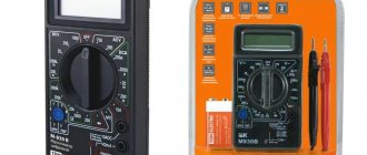
is well known to everyone from practical physics lessons at school (Figure 1). But they are not used in everyday life and by professionals due to impracticality. - A multimeter
is an electronic device that performs many different measurements, including current measurements (Figure 2). Very widespread, both among electricians and in everyday life. I have already described how to use it to measure current strength in this article. - A tester
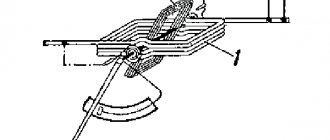
is practically the same as a multimeter, but without the use of electronics with an arrow that indicates the measurement value by divisions on the screen. Rarely seen today, they were widely used during Soviet times. - measuring clamps
(Figure 3), these are the ones I use in my work, because they do not require breaking the conductor for measurement, there is no need to go under the voltage and disconnect the load. It's a pleasure to measure with them - quickly and easily.
What is direct electric current?
If we could see the electric charges flowing in a conductor, we would notice that they constantly replace each other, moving in the same direction. As a result, it turns out that the position in space of electric charges at each moment remains unchanged or stationary.
The role of charge transporters are: Electrons, ions, cations, anions and in semiconductors - holes. Electrical sources for producing direct current are converters of chemical, mechanical, electromagnetic or other energy into electrical energy.
When direct current passes through a conductor, a constant (stationary) electric field always arises.
Electric charges moving in such an electric field do not disappear anywhere and do not accumulate anywhere. Otherwise, this would certainly change the field and then the electric current would no longer be constant.
How to measure current correctly.
In order to measure the power for DC consumers, it is necessary to connect one clamp from an ammeter, tester or multimeter to the positive terminal of the battery or a wire from a power supply or transformer, and the second clamp to the wire going to the consumer and after switching on the DC measurement mode with reserve for the upper maximum limit - take measurements.
Be careful when opening a working circuit, an arc appears, the magnitude of which increases with the current strength.
In order to measure the current for consumers connected directly to an outlet or to an electrical cable from the home power supply, the measuring device is switched to the alternating current measurement mode with a margin at the upper limit. Next, the tester or multimeter is connected to the phase wire break. We read what a phase is in this article.
All work must be carried out only after the tension has been removed.
After everything is ready, turn it on and check the current strength. Just make sure that you do not touch exposed contacts or wires.
Agree that the methods described above are very inconvenient and even dangerous!
current clamps to measure current for a long time.
(pictured on the right). They often come in the same case with a multimeter.
It’s easy to measure with them - we turn it on and switch it to the AC measurement mode, then we separate the mustaches located on top and pass the phase wire inside, after that we make sure that they fit tightly to each other and take measurements.
As you can see, it’s quick, simple, and you can measure the current under voltage using this method, just be careful not to accidentally short-circuit adjacent wires in the electrical panel.
Just remember that for correct measurements, you need to make a girth of only one phase wire,
and if you wrap around a solid cable in which phase and zero go together, it will not be possible to carry out measurements!
Purpose of the lecture:
study the basic methods and means of measuring current and voltage in radio circuits
Questions:
- General information. Classification of voltmeters and ammeters.
General information about electromechanical devices
General information about electronic voltmeters
Literature on the discipline:
Main: 1. Metrology and radio measurements: Textbook for universities./.I. Nefedov, V.I. Khakhin, V.K. Bityukov and others / Ed. prof. Nefedova. – M.: Higher. school, 2006. – 526 p.
Literature on the topic of the lecture:, p. 176-214
Procedure for measuring current
If, when determining the voltage value, the device is connected to the circuit in parallel, then in this case it is included in its break. The value of the current flowing through the sensitive element of the multimeter is reflected on its LCD screen or scale (the value is shown by the arrow).
How to break the circuit in which the current is measured? Depending on the circumstances. For example, unsolder one of the terminals of a radio component. In some cases, you will have to cut the conductor. If you use a multimeter to measure the current of a battery or battery, then it’s even easier. The chain is assembled from scratch.
What to consider when measuring
A limiting resistance must be included in the measuring circuit. This could be a resistor or an “Ilyich light bulb” (its filament). They allow you to protect the multimeter from failure. Simply put, it will not “burn out.”
If the current indicator does not show the current, it means that the measurement limit is selected incorrectly. It should be reduced by 1 position. And so on until some value appears. The measurement is carried out briefly. Touching the wires with the probe - no more than a couple of seconds
This is especially important when measuring current from low-power power supplies. For example, batteries
Long-term measurement can lead to partial or even complete discharge of the element.
Here, in principle, are all the instructions for measuring current in an electrical circuit with a multimeter. There is nothing complicated here.
Recommended for you:
How to transmit electricity meter readings via the Internet, telephone and terminal Repairing LED lamps - main faults and how to fix them yourself What to do if an energy-saving fluorescent light bulb breaks?
Measurements
Using an electronic tester is convenient because you don’t have to look for the right scale, count divisions, and determine the readings. They will be displayed on the screen accurate to two decimal places. If the measured value has polarity, then a minus sign will also be displayed. If there is no minus sign, the measurement value is positive.
How to measure resistance with a multimeter
To measure resistance, move the switch to the area indicated by the letter Ω. Select any of the ranges. We apply one probe to one input, the second to the other. The numbers that appear on the display are the resistance of the element you are measuring.
How to use a multimeter to measure resistance
Sometimes what appears on the screen is not numbers. If 0 “jumps out,” then you need to change the measurement range to a smaller one. If the words “ol” or “over” are highlighted, the value is “1”, the range is too small and needs to be increased. That's all the tricks for measuring resistance with a multimeter.
How to measure current
To select a measurement mode, you must first determine whether the current is direct or alternating. There may be problems with measuring AC parameters - this mode is not available on all models. But the procedure is the same regardless of the type of current - only the position of the switch changes.
D.C
So, having decided on the type of current, we set the switch. Next, you need to decide which socket to connect the red probe to. If you don’t even know approximately what values to expect, so as not to accidentally burn the device, it is better to first install the probe in the upper (leftmost in other models) socket, which is labeled “10 A”. If the readings are small - less than 200 mA, move the probe to the middle position.
The situation is exactly the same with the choice of measurement range: first set the maximum range, if it turns out to be too large, switch to the next smaller one. Do this until you see the readings.
How to connect a multimeter to measure DC current
To measure current, the device must be connected to an open circuit. The connection diagram is shown in the figure. In this case, it is important to install the red probe on the “+” of the power source and touch the black probe to the next element of the circuit. When measuring, do not forget that there is power, work carefully. Do not touch the bare ends of the probe or circuit components with your hands.
Alternating current
You can try the AC current measurement mode on any load connected to a household electrical outlet and thus determine the current consumed. Since in this mode the device must be connected to an open circuit, difficulties may arise with this. You can make a special cord for measurements, as in the photo below. There is a plug at one end of the cord, a socket at the other, cut one of the wires, attach two WAGO connectors to the ends. They are good because they also allow you to clamp the probes. After the measuring circuit is assembled, we proceed to measurements.
Measuring AC current with an electronic multimeter
Move the switch to the “alternating current” position, select the measurement limit. Please note that exceeding the limits may damage the device. At best, the fuse will burn out, at worst, the “filling” will be damaged. Therefore, we act according to the scheme proposed above: first we set the maximum limit, then gradually reduce it. (don’t forget about rearranging the probes in the sockets).
AC current measurement circuit
Now everything is ready. First, connect the load to the outlet. Maybe a table lamp. We insert the plug into the network. Numbers appear on the screen. This will be the current consumed by the lamp. In the same way, you can measure the current consumption for any device.
Voltage measurement
The voltage can also be variable or constant; accordingly, select the required position. The approach to choosing a range is the same: if you don’t know what to expect, set it to the maximum, gradually switching to a smaller scale. Do not forget to check whether the probes are connected correctly and into the correct sockets.
In this case, the measuring device is connected in parallel. For example, you can measure the voltage of a battery or a regular battery. We set the switch to the DC voltage measurement mode position, since we know the expected value, we select the appropriate scale. Next, use the probes to touch the battery on both sides. The numbers on the screen will be the voltage that this battery produces.
How to use a multimeter to measure voltage
How to use a multimeter to measure AC voltage? Yes, exactly the same. Just choose the right measurement limit.
Testing wires using a multimeter
This operation allows you to check the integrity of the wires. On the scale we find a continuity sign - a schematic representation of the sound (look at the photo, but there is a double mode, or maybe there is only a continuity sign). This image was chosen because if the wire is intact, the device makes a sound.
Dial mode on the multimeter measurement scale
We put the switch in the desired position, the probes are connected as usual - into the lower and middle sockets. We touch one edge of the conductor with one probe, and the other with the other. If we hear a sound, the wire is intact. In general, as you can see, using a multimeter is not difficult. Everything is easy to remember.
In this article we will tell you how to measure current using a multimeter. It's simple! Let's figure it out together. First, a little theory.
Current strength is one of the most important parameters of an electrical circuit, which is understood as the ratio of the amount of charge passing through the cross-section of a conductor for a specific time to this time interval.