Algorithm for solving problems using Kirchhoff's laws
Problems involving the application of Kirchhoff's law are not solved often at school, and not in all classes.
While working at school, I gave Kirchhoff’s laws only to those children who were preparing for physics Olympiads and to students who were preparing for universities. Problems using Kirchhoff's laws are not even available in all collections of problems recommended for use in high school.
Below is an algorithm for solving problems on this topic. The algorithm is not complicated. Using this algorithm will help you solve problems on this topic.
So, let's begin. First, you need to do some preparatory work.
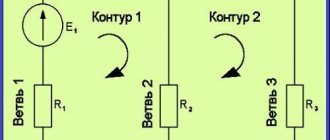
- redraw the diagram
- indicate the direction of the EMF of current sources
- indicate the expected direction of the currents flowing in each resistor (if the final answer is negative, then the direction of the current was initially chosen incorrectly)
- select the traversal direction for all linearly independent contours
After carrying out the preliminary operations, we begin to actually solve the problem itself.
- We write down Kirchhoff's first law: the sum of the currents flowing into and out of a given node is equal to zero.
Important! If current flows into a node, then it is taken with a “plus” sign; if it flows out, then with a “minus” sign. The number of equations of Kirchhoff's second law is n-1, where n is the number of nodes in this circuit. (A node is a point at which three or more conductors are connected.)
- We write Kirchhoff's second law for all linearly independent circuits: The sum of the emf in the circuit is equal to the sum of the voltage drops in each of these circuits.
Important! If the direction of the EMF coincides with the direction of bypassing the circuit, then the EMF value is taken with a plus sign. If the direction of the EMF does not coincide with the direction of bypassing the circuit, then the EMF value is taken with a minus sign. If the direction of the current coincides with the direction of bypassing the circuit, then the voltage drop in this section is taken with a “plus” sign. If the direction of the current through any resistor does not coincide with the direction of bypass in this circuit, then the voltage drop is taken with a minus sign.
We solve the system of resulting equations for unknown quantities.
Most often, in problems of this type, the main difficulty is solving the system of resulting equations.
Below is an example of solving a problem using Kirchhoff's laws. Pay attention again to the main steps of the solution. They are fully consistent with the algorithm described above.
Here is the condition of this problem.
The electrical circuit consists of two galvanic cells, three resistors and an ammeter. In this circuit, R1 = 100 Ohm, R2 = 50 Ohm, R3 = 20 Ohm, EMF of the element ?1 = 2 V. The ammeter registers a current I3 = 50 mA, flowing in the direction indicated by the arrow. Determine the emf ?2 of the second element. Neglect the resistance of the ammeter and the internal resistance of the sources.
Good luck mastering this rather complex topic!
You can leave any questions you have in the comments.
Source
Problem 2
Knowing the resistance of the resistors and the emf of three sources, find the emf of the fourth and the currents in the branches.
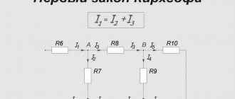
As in the previous problem, we begin the solution by composing equations based on Kirchhoff’s first law. Number of equations n-1= 2
Then we compose equations according to the second law for three circuits. We take into account the directions of the traversal, as in the previous problem.
Based on these equations, we create a system with 5 unknowns
Having solved this system in any convenient way, we find the unknown quantities
For this task, we will perform a check using a power balance, in which the sum of powers given by the sources must be equal to the sum of the powers received by the receivers.
The power balance has converged, which means the currents and EMF are found correctly.
After reading articles about Kirchhoff’s first and second laws, a dear reader may say: “Okay, MyElectronix, you told me, of course, interesting things, but what should I do next with them? So far, based on your words, I have concluded that if I put together a diagram with my own hands, then I will be able to measure these dependencies in each of its nodes and in each circuit. That's great, but I'd like to calculate patterns rather than just observe dependencies!”
Gentlemen, all these comments are absolutely correct and in response to them we can only talk about the calculation of electrical circuits using Kirchhoff’s laws. Without further ado, let's get straight to the point!
Let's start with the simplest case. It is shown in Figure 1. Let's say the EMF of the power source is E1=5 V, and the resistances R1=100 Ohm, R2=510 Ohm, R3=10 kOhm. It is required to calculate the voltage across the resistors and the current through each resistor.
Gentlemen, I will note right away that this problem can be solved in a much simpler way than using Kirchhoff’s laws. However, now our task is not to look for optimal solutions, but to use a clear example to consider the methodology for applying Kirchhoff’s laws when calculating circuits.
Figure 1 – Simple diagram
In this diagram we can see three circuits. If the question arises – why three, then I recommend looking at the article about Kirchhoff’s second law. In that article there is almost the same diagram with a visual explanation of the method for calculating the number of circuits.
Gentlemen, I want to point out one subtle point. Although there are three circuits, there are only two independent ones. The third circuit includes all the others and cannot be considered independent. And in general, in all calculations we should always use only independent contours. Don't be tempted to write another equation at the expense of this general outline, nothing good will come of it.
So, we will use two independent circuits. To do this, we specify in each contour the direction of traversal of the contour. As we have already said, this is a certain direction in the circuit, which we take as positive. To some extent, we can call this an analogue of coordinate axes in mathematics. We will draw the direction of traversal of each contour with a blue arrow.
Next, let's set the direction of the currents in the branches: we'll just put it at random. It doesn’t matter whether we guess the direction now or not. If you guessed right, then at the end of the calculation we will receive a current with a plus sign, and if we were wrong, with a minus sign. So, let's denote the currents in the branches with black arrows labeled I1, I2, I3.
Calculation of an electrical circuit according to Kirchhoff's law
Content:
Kirchhoff's laws
Equations describing the behavior of an electrical circuit are compiled based on Kirchhoff's laws. They determine the relationship between the currents and voltages of the elements forming the circuit. Equations compiled according to these laws are called Kirchhoff equations.
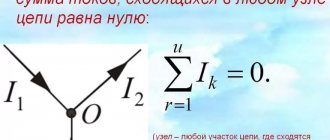
Kirchhoff's first law determines the balance of currents in the nodes of an electrical circuit.
It is formulated as follows:
The algebraic sum of the currents of the branches converging at a node of an electrical circuit is equal to zero:
In equation (3.1), currents directed from the node are written with a positive sign. Currents directed to the node are recorded with a minus sign.
The system of equations according to Kirchhoff's first law, written for all nodes of the chain, is linearly dependent. This can be easily verified by adding up all the equations. Since the current of each branch enters into two equations with different signs, the sum is identically equal to zero. Therefore, the number of independent equations according to Kirchhoff’s first law is equal to
, where is the number of nodes in the chain.
At this link you will find a complete course of lectures on the theoretical foundations of electrical engineering (TOE):
Kirchhoff's second law establishes the voltage balance in a circuit circuit:
The algebraic sum of the voltages of the branches in the circuit is equal to zero:
If the voltage of the branch coincides with the direction of bypassing the circuit, then the voltage is assigned a plus sign; if not, a minus sign is assigned. Let us transfer the voltages of the voltage sources, equal to the emf of these sources, to the right side. Equation (3.2) will take the form
In accordance with the last equality, the algebraic sum of the voltages of the branches in the circuit of the electrical circuit is equal to the algebraic sum of the emf of the sources.
The number of independent equations written according to Kirchhoff's second law is equal to the number of independent circuits. The number of such contours is determined by the formula
, where is the number of branches.
You might find these pages useful:
The order of composing equations according to Kirchhoff's laws
1. You must first select the positive directions of currents and voltages of the branches. The positive direction of the current is indicated by an arrow at the terminal of the element. The positive direction of voltage is indicated by an arrow located next to the element. The voltage polarities of the resistors are chosen to be consistent with the directions of the currents. The directions of the currents of the voltage sources are chosen to coincide with the directions of the EMF.
2. We write the equations according to Kirchhoff’s first law for
nodes
3. Select the directions for traversing the contours and write the equations according to Kirchhoff’s laws. The resistance of the conductor connecting the elements is very small compared to the resistance of the resistor and is ignored. It is convenient to select cells of the internal circuit as independent circuits. You can also use another method: select the contours in order, so that each subsequent contour contains at least one branch that is not included in the previous contours.
4. We solve the resulting system of equations and determine the currents and voltages of the circuit.
5. After determining the currents and voltages, it is necessary to perform a test. To do this, the calculated values of the variables are substituted into one of the equations compiled according to Kirchhoff’s laws.
When drawing up equations, either currents or voltages of resistive elements are considered as unknowns.
In the first case, the circuit equations are composed relative to the unknown currents of the resistive elements and voltages at the current sources. Voltages on resistive elements included in the equations according to Kirchhoff’s second law are expressed through currents according to Ohm’s law. This method of composing equations is called branch currents.
The number of jointly solved equations in the branch current method can be reduced if the circuits are chosen so that they do not include current sources. In this case, only the currents of the resistive elements will be unknown, and according to Kirchhoff’s second law, it is enough to compile
equations, where is the number of current sources.
D.C
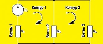
After reading articles about Kirchhoff’s first and second laws, a dear reader may say: “Okay, MyElectronix, you told me, of course, interesting things, but what should I do next with them? So far, based on your words, I have concluded that if I put together a diagram with my own hands, then I will be able to measure these dependencies in each of its nodes and in each circuit. That's great, but I'd like to calculate patterns rather than just observe dependencies!”
Gentlemen, all these comments are absolutely correct and in response to them we can only talk about the calculation of electrical circuits using Kirchhoff’s laws. Without further ado, let's get straight to the point!
Let's start with the simplest case. It is shown in Figure 1. Let's say the EMF of the power source is E1=5 V, and the resistances R1=100 Ohm, R2=510 Ohm, R3=10 kOhm. It is required to calculate the voltage across the resistors and the current through each resistor.
Gentlemen, I will note right away that this problem can be solved in a much simpler way than using Kirchhoff’s laws. However, now our task is not to look for optimal solutions, but to use a clear example to consider the methodology for applying Kirchhoff’s laws when calculating circuits.
Figure 1 – Simple diagram
In this diagram we can see three circuits. If the question arises – why three, then I recommend looking at the article about Kirchhoff’s second law. In that article there is almost the same diagram with a visual explanation of the method for calculating the number of circuits.
Gentlemen, I want to point out one subtle point. Although there are three circuits, there are only two independent ones. The third circuit includes all the others and cannot be considered independent. And in general, in all calculations we should always use only independent contours. Don't be tempted to write another equation at the expense of this general outline, nothing good will come of it.
So, we will use two independent circuits. To do this, we specify in each contour the direction of traversal of the contour. As we have already said, this is a certain direction in the circuit, which we take as positive. To some extent, we can call this an analogue of coordinate axes in mathematics. We will draw the direction of traversal of each contour with a blue arrow.
Next, let's set the direction of the currents in the branches: we'll just put it at random. It doesn’t matter whether we guess the direction now or not. If you guessed right, then at the end of the calculation we will receive a current with a plus sign, and if we were wrong, with a minus sign. So, let's denote the currents in the branches with black arrows labeled I1, I2, I3.
We see that in circuit No. 1 the direction of the currents I1 and I3, as well as the direction of the power source, coincide with the direction of the bypass, so we will count them with a plus sign. In circuit No. 2, the current I2 will coincide with the direction of the bypass, therefore it will have a plus sign, and the current I3 is directed in the other direction, therefore it will have a minus sign. Let's write Kirchhoff's second law for circuit No. 1:
Direct current: Kirchhoff's laws
When solving problems using Kirchhoff's laws, it is better to adhere to a certain algorithm: 1. determine the number of unknown currents - how many equations should be in the system; 2. determine the number of nodes - equations according to the first law, then you need to create one less; 3. draw contours and write equations for them according to the second law. For those who want to understand it thoroughly, there is a video.
Task 1. Two elements with B and B are connected according to the circuit shown in the figure. Ohm resistance. The internal resistance of the elements is the same Ohm. Determine the current flowing through the resistance.
To task 1
Let us designate the currents in the branches arbitrarily. According to Kirchhoff's first law, the sum of the currents converging at a node is equal to 0:
We will go around the upper contour counterclockwise. According to Kirchhoff’s second law, the sum of the voltage drops in the circuit is equal to the sum of the emf:
We will go around the second circuit clockwise:
There are three unknown currents, we have compiled three equations. This is enough to find the currents:
Let us express from the second equation, and from the third:
Let's substitute these expressions into the first equation:
Then the currents and
Answer: A, A, A. Task 2. Find the current strength in all sections of the circuit if V, V, V, Ohm, Ohm, Ohm, Ohm, Ohm, Ohm.
To task 2
We designate the currents in the branches arbitrarily, select the directions of circuit bypasses and the circuits themselves. We compose a system of equations. First, let's create an equation according to Kirchhoff's first law - we have two nodes, so there will be one equation. Then, bypassing the contours, we will compose two equations according to the second law: there are two of them that need to be composed, since there are three unknown currents in the circuit.
We solve the system and find the answer (I solved it using an online calculator): , , .
Answer: , , .
Task 3. In the circuit shown in the figure, find the current through the galvanometer, if V, kOhm; V, kOhm. Neglect the resistance of the galvanometer.
To problem 3
We don’t know the resistance of the galvanometer; let’s write two equations for the voltage across it:
Equating, we get
Note that if , then the equality will be satisfied. Thus, no current flows through the galvanometer.
Answer: .
Problem 4. In the circuit V‚ V, Ohm, Ohm. Find the distribution of currents in the circuit. Do not take into account the internal resistance of current sources.
To problem 4
We designate the currents in the branches arbitrarily, select the directions of circuit bypasses and the circuits themselves. We compose a system of equations. First, let's create an equation according to Kirchhoff's first law - we have three nodes, so there will be two equations. Then, bypassing the contours, we will compose three equations according to the second law: there are exactly three of them that need to be composed, since there are six unknown currents in the circuit.
We solve the system and find the answer (I solved it using an online calculator): , , , , , .
Answer: , , , , , . Problem 5. What current strength will the ammeter show in the circuit shown in the figure? Neglect the resistance of the ammeter.
To problem 5
Let us designate the currents in the circuit arbitrarily. Let us denote the directions for traversing the contours. Let's write a system of equations: we will compose three equations according to the first law (one less than the number of nodes) and three equations according to the second law, since there are six unknown currents and the system should consist of six equations.
To use the calculator, I entered Ohm and V. The result was: , , , , , .
The minuses indicate the opposite direction of the current in this branch to what we drew.
Problems using Kirchhoff's rule with solutions
We have already written about Ohm's law, as well as parallel and series connection of conductors. But these were flowers. Today we will deal with more difficult problems: let’s see how problems using Kirchhoff’s rules are solved.
Don’t forget to subscribe to our telegram channel: there you will find the latest education news, useful life hacks and discounts for students.