Inhomogeneous section of the DC circuit
Definition of main parameters and processes:
- the movement of charges (q) is characterized by density, which depends on the cross-sectional area (S) and current strength;
- at concentration (n), you can calculate the number of unit charges (q0) moved per unit time;
- this quantity can be depicted as a cylindrical section of a conductor with volume ( V ):
q = q0*n*V.
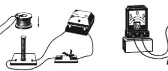
If you connect the battery terminals to a conductor, the power supply will be discharged. To maintain the process of moving charges for a long time, you can create a path closed in a ring. However, even in this case, the free drift of electrons is limited by joint collisions and the opposition of charges of the molecular lattice of the material. To compensate for resistance, it is necessary to apply additional “third-party” forces.
An example of a non-uniform section of a chain
The figure shows the factors that should be taken into account. To calculate the tension at any point in this circuit, you need to sum up the vector components Eq and Est (Coulomb and external forces, respectively). The given Ohm's law for a non-uniform area determines that the current strength (I12) = voltage in a given area (U12) / total electrical resistance (R).
To transfer a unit charge q from point “1” to point “2”, it is necessary to perform work A12. This will require the creation of a certain potential difference (ϕ1-ϕ2). A direct current source creates an electromotive force (EMF), which is capable of moving charge through the circuit. The total stress will contain the sum of the listed forces.
Below are the formulas characterizing the considered example:
- A12/q = ϕ1 – ϕ2;
- Ast/q = E12;
- U = A12/q + Ast/q = ϕ1 – ϕ2 + E12;
- I = (ϕ1 – ϕ2 + E12)/ R.
An integrated version of the representation of the processes under consideration will give a similar result.
For your information. When performing calculations, the actual polarity of the DC source must be taken into account. Depending on the connection, the corresponding EMF will promote or hinder the movement of charge.
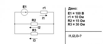
The following example demonstrates the solution to a practical problem. It is necessary to calculate the current in the circuit, which is made up of a power source with EMF = 40V and wiring with electrical resistance R = 5 Ohm. The potentials measured at the output are:
ϕ1= 20V; ϕ2=10V.
By substituting the values into the formula, you can get the desired result:
(20-10+40)/5 = +10A.
The plus sign means that the current flows in the direction from point “1” to “2”.
If we consider the process in differential form, we can imagine a “cloud” created from a certain number (N) of charges. It moves in the conductor with a certain drift speed (Vdr). Three types of forces act on it:
- Coulomb - Fcoul;
- third-party – Fc;
- crystal lattice resistance – Fsp.
The latter indicator will depend on the characteristics of the material. It can be expressed as specific conductivity. The current density vector will be equal to the sum of the EMF vectors (Coulomb and extraneous nature) divided by the resistivity.
Moscow State University of Printing Arts
7.
Lecture 7. Closed electrical circuits
7.1. Outside forces. Electromotive force (EMF) and voltage
7.2. Ohm's law for a non-uniform section of a circuit and a closed circuit. Current source efficiency
7.3 Kirchhoff's rules
7.1.
Outside forces. Electromotive force (EMF) and voltage
Let us consider by what means the current flow can be maintained, i.e. constant voltage at the ends of the conductor.
Let there be a potential difference at the ends of a conductor of length l that creates an electric field E inside it, directed in the direction of the potential drop, because
In this case, an electric current arises in the conductor, which flows from a higher potential to a lower potential. A prerequisite for the existence of current is the presence of a potential difference, and to maintain it it is necessary to have a device with the help of which the separation of electrical charges at the ends of the conductor will occur. Such a device is called a current source.
Galvanic cells, batteries, thermoelements, and electric generators are used as current sources.
The current source simultaneously performs a second task - it closes an electrical circuit through which the continuous movement of charges could be carried out. Current flows through the outer part - the conductor and through the inner part - the current source.
The current source has two poles: positive with a higher potential and negative with a lower potential.
The separation of charges in a current source is carried out with the help of external, so-called third-party forces directed against Coulomb (electrostatic) forces acting on unlike charges in the conductors of the current source itself.
The nature of external forces can be very different: mechanical, chemical, thermal, biological.
If a circuit consisting of a conductor and a current source is closed, then current passes through it and at the same time work is done by external forces.
The work of external forces to move a single positive charge along a closed circuit is called electromotive force (EMF):
The current source is characterized by the magnitude of the emf and internal resistance r. We will consider the direction of action of external forces on positive charges to be the direction of action of the EMF.
The section of the electrical circuit in which external forces act is called inhomogeneous.
It contains a current source with emf, internal resistance r and a load with resistance R.
The total work done by Coulomb forces and external forces when moving a charge along a circuit is equal to:
where is the work of Coulomb forces, and is the work of external forces.
Voltage U in a given section of the circuit is a value equal to the ratio of the total work done when moving a charge to the value of this charge:
Or taking into account the dependencies we get:
the voltage across a section of the circuit is equal to the sum of the potential difference and the electromotive force.
The voltage at the ends of a section of the circuit is equal to the potential difference only if there is no EMF acting on this section.
The direction of action of the EMF coincides with the direction from “-” to “+” on the symbolic designation. For example, for the closed circuit in Fig. thirty .
The expression can be written as
where I(R+r) is called the voltage drop across the resistance (R+r).
In this case, the rule of signs is valid: before (or I) the “+” sign is taken if the direction of the EMF (or the direction of the current) coincides with the direction from 1 to 2, and vice versa.
For example, for the section of the chain shown in Fig. 31,
7.2.
Ohm's law for a non-uniform section of a circuit and a closed circuit. Current source efficiency
Ohm's law for a non-uniform section of a chain has the form:
If the electrical circuit is closed, then points 1 and 2 coincide, and the total resistance of the entire circuit is equal to r + R, therefore Ohm’s law for a closed circuit:
where is the algebraic sum of all emfs applied in this circuit.
If the circuit is open, and, therefore, there is no current in it (I = 0), then this means that the emf applied in the open circuit is equal to the potential difference at the ends. Thus, to find the EMF of a current source, the potential difference at its terminals should be measured when the external circuit is open.
When several current sources are connected in series, the total emf of the battery is equal to the algebraic sum of the emf of all sources, and the total resistance is equal to the sum of the resistances, i.e.
When connecting n sources in parallel with the same EMF and internal resistance, r is the total EMF of one source and the internal resistance
When electric current I passes through a closed circuit, power is released in all its sections. The total power developed by the source goes to heat release in the external and internal resistances, and is equal to:
Net power released at load R:
If we examine the dependence (R), we can obtain the following: the function takes a maximum under the condition of equality R = r.
The power released in the internal resistance cannot be used and is called wasted power.
The coefficient of performance (efficiency) of a current source is the ratio of useful power to total power:
Under the condition R=r, when maximum power is allocated to the load, efficiency = 1/2, and this does not mean that efficiency is maximum.
At maximum current in a closed circuit (short circuit)
useful power = 0, because R=0.
7.3.
Kirchhoff's rules
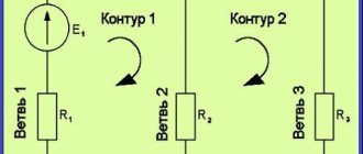
If the emfs of the sources are different, then it is convenient to use Kirchhoff’s rules to calculate the current strengths in different sections of a branched circuit.
- Kirchhoff's first rule.
The point where several conductors connect is called a node. The algebraic sum of currents in a node is equal to zero:
Currents flowing to a node are considered positive, and from a node - negative.
- Kirchhoff's second rule.
The algebraic sum of the voltage drops on a closed loop of a branched circuit is equal to the algebraic sum of the emf:
It is necessary to agree on the direction of traversing the contour. The choice of this direction is completely arbitrary. All currents coinciding in direction with the direction of bypassing the circuit are considered positive. The EMF of current sources connected in different parts of the circuit are considered positive if they create a current directed towards bypassing the circuit.
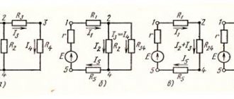
For example, for a closed loop ABCD (Fig. 33) in the case of a clockwise bypass, the Kirchhoff equation is written as follows:
The task of calculating currents in various sections of a branched circuit
Calculate the currents in all sections of the circuit shown in Fig. 33, b), if = 2V, = 4 V, Ohm, R = 9 Ohm.
Solution.
Let us choose the direction of the currents, as indicated in Fig. 33, b. For node A we write the first Kirchhoff rule:
Consider a closed loop , R, the direction of traversing the loop is counterclockwise. Let's write down Kirchhoff's second rule:
Also for contour, R
We have obtained a system of three equations for three unknowns. Let's solve the system of equations:
We finally get: I = 0.3 A, = -0.35 A, = 0.65 A. The minus sign means that the current through the circuit section flows in the direction opposite to the one we chose.
Test questions and tasks
- Give examples of outside forces. Where do they operate?
- What determines the magnitude of the EMF of a current source?
- Write down Ohm's law for a non-uniform section of the circuit.
- Write Ohm's law for a closed circuit.
- A current source with an emf of 6.4 V and an internal resistance of 2 ohms powers three series-connected light bulbs with a resistance of 10 ohms each. Find the voltage drop across each light bulb.
- How is the efficiency of a current source determined?
- Two identical resistances are connected to a current source in series and in parallel. In which case will the efficiency be greater?
- What is the voltage across a section of a circuit?
- Write down Kirchhoff's rules. Where are they used?
Ohm's law for a closed circuit
Ohm's law for a circuit section
In a real situation, the electrical resistance of the load (Rl) and the power source itself (Ri) should be taken into account. The classic formula is supplemented as follows:
I = E/(Rn+Ri).
If we add Ri=1Ohm to the example discussed above, we get I = (ϕ1 – ϕ2 + E12)/(Rн+Rи) = (20-10+40)/(5+1) = +8.33A. One can see a decrease in the current in the circuit due to an increase in the total electrical resistance. To compensate for losses to connect a more powerful load, it is necessary to increase the source EMF.
What does Ohm's law sound like for a section of a circuit?
The current in a conductor arises in an electric field, which, in turn, appears in the presence of a potential difference or voltage.
The movement of current is directed towards the lower potential. It is conventionally believed that positive charges move in this direction, and free electrons move in the opposite direction. On a section of a metal conductor, this process will look like this. At each end there is a potential - ϕ1 and ϕ2, with ϕ1 > ϕ2. Therefore, the voltage at this place is equal to U = ϕ1 – ϕ2. The German scientist Ohm practically established a relationship in which as the voltage increases, the current flowing through the incomplete section also increases.
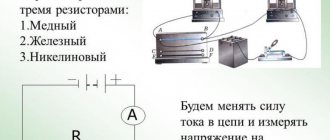
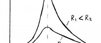
For each of the conductors, differing in materials, a graph was constructed showing the dependence of current on voltage. Subsequently, these graphs became known as current-voltage characteristics. As a result, it was established that there is a linear relationship between both quantities - current and voltage. That is, they are in direct proportion.
But, as the graphs show, all conductors have different proportionality coefficients. Consequently, they have different degrees of conductivity, called electrical resistance (R). Therefore, the lower the resistance of the conductor, the higher the current passing through it. Given that the voltage for all conductors will be the same.
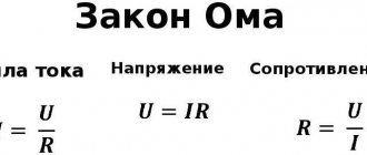
After all the experiments, the scientist was able to finally formulate his law for the chain section:
The current strength in a homogeneous conductor in a separate section is in direct proportion to the voltage in the same section and in inverse proportion to the resistance of this conductor.
Classic formulation
Ohm's law in differential form
For a circuit section without an EMF source, it is sufficient to use the classical Ohm's law:
I (current) = U (voltage) / R (electrical resistance).
This ratio was established experimentally at the beginning of the 19th century. The name retains the name of the German scientist who made the discovery. The voltage is determined by the potential difference at the ends of the conductor:
U = ϕ1 – ϕ2.
Elementary calculations show the mutual dependencies of the listed parameters:
- I1 = 24/6 = 4A;
- I2 = 60/6 = 10A.
By increasing the potential difference, with a constant resistance, a greater current strength is obtained:
I2 > I1.
To reduce the current to the desired level, when working with a certain power source, change the resistance:
- I1 = 24/4 = 6A;
- I2 = 24/12 = 2A.
Basic formulas
To remember the rules, use this picture. To calculate a specific parameter, close the corresponding segment. The relative arrangement of the remaining components will roughly depict the required formula.
Current, voltage and resistance
This picture clearly demonstrates the mutual influence of those basic electrical parameters. With its help, you can explain the features of practical application using the example of a typical home power supply network project.
Modern residential buildings often use air conditioners, ovens, and other appliances with high power consumption. For normal operation, it is necessary to increase the current because the voltage is limited by standards. Step-up transformers are not useful in this case, since serial products are designed for connection to a 220 (380) V network.
As the current increases, conductors with a sufficiently large cross-section will be needed. Otherwise, the concentration of charges per unit volume will increase to a critical value. The impact on the crystal lattice will increase the temperature of the metal to the point of mechanical destruction of the wiring.
To eliminate problems, in addition to cable products, circuit breakers are carefully selected. To create a power supply project and a list of suitable functional components, use the formulas presented above.
Ohm's law for alternating current
If there is inductance or capacitance in an AC circuit, its reactance must be taken into account. In this case, the entry for Ohm's Law will look like:
I = U/Z
Here Z is the total (complex) resistance of the circuit - impedance. It includes active R and reactive X components. Reactance depends on the ratings of the reactive elements, on the frequency and shape of the current in the circuit. You can learn more about complex resistance on the impedance page.
Taking into account the phase shift φ created by reactive elements, Ohm’s Law is usually written for a sinusoidal alternating current in complex form: – complex current amplitude. = Iampe jφ – complex voltage amplitude. = Uampe jφ – complex resistance. Impedance. φ – phase angle between current and voltage. e is a constant, the base of the natural logarithm. j is the imaginary unit. Iamp, Uamp – amplitude values of sinusoidal current and voltage.
For EMF
Before considering Ohm's law for a complete (closed) circuit, I will give a sign rule for EMF, which states: If inside the EMF source the current flows from the cathode (-) to the anode (+) (the direction of the field strength of external forces coincides with the direction of the current in the circuit, then the EMF of such a source is considered positive, otherwise the EMF is considered negative.
A practical application of this rule is the possibility of bringing several sources of EMF in a circuit to one with the value E=E1+E2+…+En, naturally, taking into account the signs determined by the above rule. For example (Fig. 3.3) E=E1+E2-E3. In the absence of a back-to-back source E3 (in practice this almost never happens), we have a widespread serial connection of batteries, in which their voltages are summed.
For a complete chain
Ohm's law for a complete circuit - it can also be called Ohm's law for a closed circuit, has the form I=E/(R+r). The above formula for Ohm's law contains the notation r, which has not yet been mentioned. This is the internal resistance of the EMF source. It is quite small, in most cases it can be neglected in practical calculations (provided that R>>r - the circuit resistance is much greater than the internal resistance of the source). However, when they are comparable, the value of r cannot be neglected.
As an option, we can consider the case in which R=0 (short circuit). Then the given formula of Ohm's law for the complete circuit will take the form: I=E/r, that is, the value of the internal resistance will determine the short-circuit current. This situation may well be real. Ohm's law is discussed here quite briefly, but the formulas given are sufficient to carry out most calculations, examples of which, as other materials are posted, I will give.
A complete circuit is made up of a section (sections), as well as a source of EMF. That is, in fact, the internal resistance of the EMF source is added to the existing resistive component of the circuit section. Therefore, it is logical to slightly change the above formula:
Using Ohm's Law in Parallel and Series Connections
In a series connection, the circuit elements are connected one after another in series. Since such an electrical circuit is unbranched, the current strength in each section will be the same. An example of a series connection is light bulbs in a New Year's garland.
When connecting elements in series, the main parameters of the electrical circuit are calculated as follows:
Where \(I\) is the total current strength in the electrical circuit, \(I_1\) is the current strength of the first section, \(I_2\) is the current strength of the second section, \(I_3\) is the current strength of the third section.
Where \(U\) is the total voltage, \(U_1\) is the voltage of the first section, \(U_2\) is the voltage of the second section, \(U_3\) is the voltage of the third section.
- Resistance according to the formula:
Where \(R\) is the total resistance in the circuit, \(R_1\) is the resistance of the first section, \(R_2\) is the resistance of the second section, \(R_3\) is the resistance of the third section.
By connecting elements in a circuit in parallel, a branched electrical circuit is obtained. An example of such a connection is the standard electrical distribution in an apartment, when several household appliances and overhead lighting can be turned on in a room at the same time.
When connecting elements in parallel, the main parameters of the electrical circuit are calculated as follows:
Where \(I\) is the total current strength in the electrical circuit, \(I_1, I_2, I_3\) is the current strength of the first, second and third sections, respectively.
Where \(U\) is the total voltage, \(U_1, U_2, U_3\) is the voltage of the first, second and third sections, respectively.
Where \(R\) is the total resistance in the circuit, \(R_1, R_2, R_3\) is the resistance of the first, second and third sections, respectively.