Calculation of electrical circuits using the equivalent resistance method (circuit folding method)
The equivalent resistance method is used to calculate electrical circuits in which there are passive elements connected to each other in series, parallel or in a mixed circuit. The method consists of sequentially replacing individual resistance groups with one equivalent one until the simplest circuit is obtained (see Fig. 13d). Each current in the circuit is then determined.
Figure 13. Chain folding method
Determination of equivalent resistances
Let us turn to the diagram shown in Figure 13a. Resistances and are connected in series. That's why . These two resistances can be replaced with one (equivalent) one, then the circuit will be simplified (Figure 13b).
The resistances are connected in parallel and they can also be replaced with one equivalent: .
Then the diagram will become even simpler (Figure 13c).
In the circuit in Figure 13c, resistances , and are connected in series and can be replaced by one equivalent one. The diagram will be simplified even more (Figure 13d).
With similar transformations, the scheme of mixed connection of passive elements with one energy source can in most cases be reduced to the simplest scheme (Figure 13d). In more complex circuits, the equivalent resistance method achieves a simplification that greatly facilitates further calculations.
Determination of currents
The definition begins with the simplest diagram (Figure 13d).
According to Ohm's law: because ; .
Knowing it is easy to find and. .
Problem 1
= 20 Ohm, = 30 Ohm, = 12 Ohm, = 8 Ohm, = 1.5 Ohm, = 160 V, = 0.5 Ohm. Determine the currents in all elements of the circuit and the efficiency of the source (Figure 13a).
Problem 2
Current = 3 A. Resistance values are the same. Determine the EMF and source power (Figure 13a).
Resistance triangle and star transformation method
Passive elements in electrical circuits are connected not only in series and in parallel. In a number of circuits, groups of three elements can be distinguished, forming a triangle or resistance star , which cannot be calculated by the convolution method.
When calculating such circuits, the resistance triangle is first converted into an equivalent star or vice versa, and then the convolution method is applied to the converted circuit.
Let's consider the circuit of a resistance value meter (Figure 14a). In this circuit there are no elements connected in series or parallel, but there are closed circuits of three resistances (resistance triangles).
A triangle is attached to the nodal points a,b,c . It can be replaced according to certain rules by an equivalent three-rayed star attached to the same points a, b, c (Figure 14b).
Figure 14. Resistance triangle and star transformation
Converting a Resistance Triangle to an Equivalent Star
Replacing the resistance triangle with an equivalent star and vice versa is carried out on the condition that such a replacement does not change the potentials of the node points a, b, c and the operating mode of the rest of the circuit does not change (currents, voltages and powers do not change).
Consider the circuits in Figures 14c) and 14d). These circuits must be equivalent for all cases , and in particular for current. In this case, in the triangle circuit between points b and c, two parallel branches with resistances are included. The total resistance between these points is:
In the star circuit, between points b and c, resistances and are connected in series.
That's why: .
Assuming , and then similarly we obtain:
;
Having solved this system of three equations, we obtain: ;
Converting a Resistance Star to an Equivalent Triangle
In the same original circuit, we replace the star formed by resistances and with a conductivity triangle (Figure 15a).
Figure 15. Transformation of a resistance star into an equivalent triangle
Task
Determine the currents in the circuit shown in Figure 15a), if
= 12 Ohm, = 18 Ohm, = 6 Ohm, =18 Ohm, =18 Ohm, =132 V.
Control questions
1. What is the method of winding up an electrical circuit?
2. Explain the transformation of a resistance triangle into an equivalent resistance star.
3. Explain the transformation of a resistance star into an equivalent resistance triangle.
An example of calculating a circuit with determining the potentials of its points relative to an arbitrarily selected
“common point” (“ground”).
Calculation of the circuit involves, in addition to determining all currents flowing in the circuit, calculating the potential of each point of the circuit relative to the “common point” (CP). Sometimes OT is also called “earth” or “grounding”. In the electrical circuit, one of the points of the circuit is selected OT, i.e. its potential is conventionally assumed to be zero. Typically this point is connected to the body of the device or to the neutral wire of the electrical network. At the beginning of the calculation, it is not always clear which point of the circuit should be chosen by the OT, and during the calculation process it is necessary to repeatedly determine the potentials of all points relative to one or another OT. Let's consider what to do to minimize calculations.
For example, you need to calculate the circuit shown in Figure 16, i.e. determine the currents flowing in all branches and determine the potentials of all points of the circuit relative to the OT, which in this example can be chosen either point F or point D.
Figure 16. Initial circuit Figure 17
Initial data for calculation: R1=1 Ohm; R2= R3=2 Ohm;
R4=3 Ohm; R5=1.2 Ohm; R6=1.4 Ohm; R7=6 Ohm; E=4.5 V.
We will calculate the currents using the equivalent resistance method and the first step is to replace the resistances R3, R4 and R5 with one equivalent resistance R3-5 (Figure 17).
; R3-5=0.6 Ohm.
We will replace the resistances R3-5 and R6 connected in series with the equivalent R3-6 (Figure 18). R3-6= R3-5 + R6=2 Ohm.
We will replace resistances R3-6 and R7 connected in parallel with the equivalent R3-7 (Figure 19). R3-7=
Figure 18 Figure 19
Let's calculate the current values in the circuit using the diagrams in Figures 16-19.
Current I1 (Figure 19): I1=
Voltages:
Currents (Figure 18):
Voltage (Figure 17)
Currents (Figure 16):
.
It is easy to calculate the potentials of points in a circuit whose elements are connected in series (Figure 19). Let us calculate the potentials of the points of the circuit under the assumption that OT is point F, i.e. . Then, when bypassing the circuit in the direction of flow of current I1, we obtain:
=0.
The potential of point D is calculated according to the scheme in Figure 17:
.
Based on the calculation results, we will construct a potential diagram (Figure 20). We plot the calculated potentials vertically and the resistance values horizontally in the order shown in Figure 20.
Figure 20. Potential circuit point diagrams
The potential diagram is a straight line ABCF, the tangent of the angle of inclination of which to the resistance axis represents (according to Ohm’s law for a section of the circuit) the current I1 (Figure 19). The potential diagram of the circuit section through which current I6 flows (Figure 18) is represented by the CDF line.
If we now accept point D as common ( , then according to Figure 17, the potentials of all points relative to it are:
;
.
The potential point diagram of Figure 19 in this case would be the straight line A1B1C1F1 in Figure 20, having the same slope.
As follows from the calculations and graphs, when OT changes from F to D, the potentials of all points change by the same value of the potential difference between these points (in this example, by 1.05 V).
Thus, to obtain new values of the potentials of circuit points after changing the OT, it is necessary:
- or subtract the resulting potential difference from the potential of each point,
- move the horizontal axis (resistance axis) of the potential diagram so that it passes through the newly selected OT. Then, on the same scale, it is possible to determine the potentials of other points relative to the newly adopted OT.
Calculation for mixed connection of devices
It is simply impossible to calculate the resistance of a circuit when it is branched and filled with different types of resistive connections. The solution to the problem is complicated by the many areas where parts are connected to each other in different combinations. In such circumstances, it is desirable to perform a series of transformations, achieving simplification of the circuit by introducing individual equivalent elements. In this case, suitable circuits for serial and parallel connections are identified.
For example, having found a certain number of serial connections of resistors, replace them with one equivalent component. Having determined the elements connected in series, they also draw an equivalent instead. The search for such simple connections is beginning again.
The method is called the "coagulation method". The circuit is simplified until there is only one Req left in it.
Physical formulas and calculation examples
Formulas for the equivalent resistances of a circuit consisting of a pair of resistors R 1 and R 2 can be divided into a certain series:
- parallel connection is determined by the formula Req. = (R1*R2)/R1+R2;
- sequential inclusion is calculated by determining its sum Req. = R1+R2.
The mixed connection of resistive elements does not have a specific formula. In order not to get confused during lengthy transformations, it is permissible to use a special program from the Internet. This is an “online calculator” service. It will help you understand complex connection diagrams, be it a triangle, square, pentagon or other schematic figure formed by resistive elements.
You can understand how all formulas and methods work using a specific problem. The first picture shown is a mixed electrical circuit. It includes 10 resistors. The elements are presented in the following denominations:
- R1 = 1 Ohm;
- R2 = 2 Ohm;
- R3 = 3 Ohm;
- R4 = 6 Ohm;
- R5 = 9 Ohm;
- R6 = 18 Ohm;
- R7 = 2Ohm;
- R8 = 2Ohm;
- R9 = 8 Ohm;
- R10 = 4 Ohm.
Voltage applied to the circuit:
It is required to calculate the currents on all resistive elements.
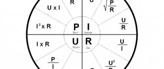
Ohm's law is used for calculations:
I = U/R, substituting the equivalent resistance for R.
Attention! To solve this problem, the total (equivalent) R is first calculated, after which the current in the circuit and the voltage on each resistive component are calculated.
By calculating Req., the given chain is divided into links containing parallel and serial connections. Calculations are made for each such link, and then for the entire chain.
The figure above shows a mixed resistance connection. It can be divided into three sections:
- AB – a section with two parallel branches;
- BC – a segment containing a sequential conjugation;
- CD is a section of a circuit with an arrangement of three parallel chains.
Resistances R2 and R3, forming the lower branch of segment AB, are connected in series, which is taken into account in the calculation.
If you look at section CD, you can note the mixed inclusion of resistive elements.
The beginning of the calculations is to determine the equivalent resistances for these mixed fragments. Do this in the following order:
- Req.2.3 = R2+R3=2 + 3 = 5 Ohm;
- Req.7.8 = (R7*R8)/R7 + R8 = (2*2)/2 + 2 = 1 Ohm;
- Reeq.7,8,9 = Reeq.7.8 + R9 = 1 + 8 = 9 Ohm.
Knowing the values of the obtained equivalents, the original circuit is simplified. It will look like the one shown in the figure below.
Next, you can determine Req. for sections AB , BC , CD , according to the formulas:
- Req.AB = (R1*Req. 2.3)/R1 + Reeq. 2.3 = (1*5)/1 + 5 = 0.83 Ohm;
- Req.BC = R4 + R5 = 6 + 9 = 15 Ohm;
- 1/Req.CD = 1/R6 + 1/Req.7,8.9 + 1/R10 = 1/18 + 1/9 + 1/4 = 0.05 + 0.11 + 0.25 = 0, 41 Ohm.
As a result of the calculations performed, an equivalent circuit is obtained, which includes three Req. resistance. It looks like the one shown in the figure below.
