Theory
Wireless electricity is literally the transfer of electrical energy without wires. People often compare the wireless transmission of electrical energy with the transmission of information, such as radios, cell phones, or Wi-Fi Internet access. The main difference is that radio or microwave transmission is a technology aimed at restoring and transporting information, and not the energy that was originally expended on transmission.
Wireless electricity is a relatively new area of technology, but one that is developing quite dynamically. Methods are now being developed to efficiently and safely transmit energy over a distance without interruption.
Ultrasound for Energy Transfer
Any wave carries energy, including high-frequency sound waves. There are three approaches to wireless transmission of electricity:
- transfer of electrical energy through conversion to another type of energy at the source and reverse conversion to electricity at the receiving device;
- creation and use of alternative conductors of electricity (plasma channels, columns of ionized air, etc.);
- use of the conductive properties of the Earth's lithosphere.
The method of using ultrasound belongs to the first approach. In a special type of ultrasound source, when power is applied, a directed beam of high-frequency sound waves appears. When they hit the receiver, the energy of sound waves is converted into electric current.
The maximum distance for transmitting electricity wirelessly is 10 meters. The result was obtained in 2011 by representatives of the University of Pennsylvania during a presentation at the exhibition “The All Things Digital”. This method is not considered promising due to several of its disadvantages: low efficiency, low voltage received, and restrictions on the strength of ultrasound radiation by sanitary standards.
How does wireless electricity work?
The main work is based specifically on magnetism and electromagnetism, as is the case with radio broadcasting. Wireless charging, also known as inductive charging, is based on a few simple operating principles, in particular the technology requires two coils. A transmitter and receiver, which together generate an alternating magnetic field of non-direct current. In turn, this field causes a voltage in the receiver coil; this can be used to power a mobile device or charge a battery.
If you send electric current through a wire, a circular magnetic field is created around the cable. Despite the fact that the magnetic field affects both the loop and the coil, it is most pronounced on the cable. When we take a second coil of wire that is not receiving any electric current passing through it, and a place where we place a coil in the magnetic field of the first coil, the electric current from the first coil will be transmitted through the magnetic field and through the second coil, creating an inductive coupling.
Let's take an electric toothbrush as an example. In it, the charger is connected to an outlet, which sends an electric current to a twisted wire inside the charger, which creates a magnetic field. There is a second coil inside the toothbrush, when current begins to flow and, thanks to the formed MF, the brush begins to charge without being directly connected to a 220 V power supply.
Digitrode
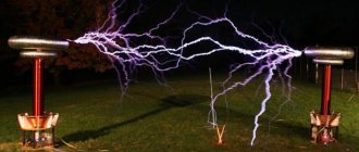
The concept of wireless power transmission is not new. It was first demonstrated by Nikola Tesla in 1890. Nikola Tesla used electrodynamic induction or resonant inductive coupling by lighting three light bulbs 60 feet from a power source. In this project we will also create a mini Tesla coil to transfer energy.
Wireless power transmission is the process of sending energy across an air gap without the use of any wires or physical connection. In this wireless system, the transmitting device generates a time-varying high-frequency electromagnetic field that transmits energy to the receiving device without any physical connection. The receiving device extracts energy from the magnetic field and supplies it to the electrical load. Therefore, to convert electricity into an electromagnetic field, two wire-wound coils are used as a transmitter coil and a receiving coil. The transmitter coil is powered by alternating current and creates a magnetic field, which is subsequently converted into useful voltage at the receiver coil. In this example, we will create a basic low-power wireless transmitter circuit to light an LED.
The circuit for wirelessly transmitting power to light an LED is simple and can be seen in the following image. It consists of two parts: a transmitter and a receiver.
On the transmitter side, the coil is connected through the collector of the transistor, 17 windings on both sides. And the receiver is built using three components - a transistor, a resistor and a center tap air core inductor or copper coil. The receiver side has an LED connected through 34 turns of copper coil. An NPN transistor is used here, you can take, for example, BC547.
The coil is an important part of wireless power transmission and must be carefully assembled. The coils in this project are made using 29AWG copper wire. The formation of the center tap coil is done on the transmitter side. Winding the coil requires a cylindrical object, such as a PVC pipe or plastic can.
For the transmitter, wind the wire up to 17 turns, then create a loop to connect the center tap and again make 17 turns of the coil. And for the receiver, make 34 turns of the coil winding without a central tap.
Both circuits in this case are implemented on breadboards and are powered by a 1.5 V battery. The circuit cannot be used for a power supply greater than 1.5 V, since the transistor may heat up with excessive power dissipation.
In the transmitter section, a transistor generates high-frequency alternating current through a coil, and the coil creates a magnetic field around it. Since the coil is rotated to the center, the two sides of the coil begin to charge. One side of the coil is connected to the resistor and the other side is connected to the collector terminal of the NPN transistor. During the charging state, the base resistor begins to conduct, which eventually turns on the transistor. The transistor then discharges the inductor when the emitter is connected to ground. This charging and discharging of the inductor creates a very high frequency oscillation signal, which is then transmitted as a magnetic field.
From the receiver side, this magnetic field is transmitted to another coil, and according to Faraday's law of induction, the receiver coil begins to generate an EMF voltage, which is additionally used to illuminate the LED.
This small circuit may work properly, but has a huge limitation. This circuit is not suitable for high power transmission and has an input voltage limitation. The efficiency is also very low. To overcome this limitation, push-pull topologies can be implemented using bipolar transistors or field-effect transistors. However, for better efficiency, it is better to use proper wireless transmission driver chips. To improve transmission range, wind the coil correctly and increase the number of turns in the coil.
© digitrode.ru
Story
Wireless power transmission, as an alternative to the transmission and distribution of electrical lines, was first proposed and demonstrated by Nikola Tesla. In 1899, Tesla presented the wireless transmission of power to a field of fluorescent lamps located twenty-five miles from the power source without the use of wires. But at the time, it was cheaper to wire 25 miles of copper wire rather than build the special power generators that Tesla's expertise required. He was never given a patent, and the invention remained in the recesses of science.
While Tesla was the first person to demonstrate the practical capabilities of wireless communication back in 1899, today there are very few devices on sale, such as wireless brushes, headphones, phone chargers and the like.
Microwave
Microwaves are special lines with a length of 12 centimeters and a frequency of 2.45 gigahertz, which are transparent to the atmosphere. Regardless of the weather, the energy loss will be 5%. First, it is necessary to convert the electric current into microwaves, then detect them and return them to the first state. The first problem was solved thanks to the installation of a magnetron, and the second - thanks to a rectenna or a special antenna.
You might be interested in this All about signal duty cycle
Microwave energy transfer
Magnetism
It is a fundamental force of nature that causes certain types of material to attract or repel each other. The only permanent magnets are the Earth's poles. The flux current in the loop generates magnetic fields that differ from oscillating magnetic fields in the speed and time required to generate alternating current (AC). The forces that appear in this case are depicted in the diagram below.
This is how magnetism appears
Electromagnetism is the interdependence of alternating electric and magnetic fields.
Magnetic induction
If the conductive loop is connected to an AC power source, it will generate an oscillating magnetic field in and around the loop. If the second conductive circuit is close enough, it will capture part of this oscillating magnetic field, which in turn generates or induces an electric current in the second coil.
Video: how wireless electricity transfer occurs
Thus, there is an electrical transfer of power from one cycle or coil to another, which is known as magnetic induction. Examples of this phenomenon are used in electrical transformers and generators. This concept is based on Faraday's laws of electromagnetic induction. There, he states that when there is a change in the magnetic flux connecting to a coil, the emf induced in the coil is equal to the product of the number of turns of the coil and the rate of change of flux.
Electric transformer
We make wireless power transmission
Humanity strives to completely abandon wires, because according to many, they limit possibilities and do not allow one to act completely freely. What if it were possible to do the same in the case of electricity transmission? You can find out the answer to this question in this review, which is dedicated to a video on the production of a home-made structure, which in a small size represents the possibility of transmitting electricity without directly connecting wires.
Let's start by watching the author's video
We will need: - small diameter copper wire 7 m long; - cylinder with a diameter of 4 cm; - AA battery; — battery box; - 10 Ohm resistor; — transistor C2482; - Light-emitting diode.
We take a wire 4 meters long and bend it in half so that there are two wires left at one end and the bent part at the other end.
We take one wire, bend it in any direction and begin to wind it onto the cylinder.
Having reached the middle, we also leave the double wire in any direction and continue winding until there is a small piece left, which also needs to be left.
The resulting ring with three ends must be removed from the cylinder and secured with insulating tape.
Now we take the second piece of wiring 3 m long and wind it in the usual way. That is, in this case we need to get not three ends, as in the case of the previous winding, but two.
We secure the resulting ring again with electrical tape.
The ends of the wire must be cleaned, because it is covered with a protective layer of varnish.
To simplify the process of assembling a homemade product, we present to your attention the author’s connection diagram.
The diagram shows that a coil with three outputs is designed to connect the power supply of the resistor and transistor, and an LED must be attached to the second coil, which has two ends.
Become the author of the site, publish your own articles, descriptions of homemade products and pay for the text. Read more here.
Power coupling
This part is necessary when one device cannot transmit energy to another device.
Magnetic coupling is generated when an object's magnetic field is capable of inducing an electric current to other devices within its range.
Two devices are said to be mutually inductively coupled or magnetically coupled when they are arranged so that a change in current as one wire induces a voltage at the ends of the other wire by means of electromagnetic induction. This is due to mutual inductance
Technology
Principle of inductive coupling
Two devices mutually inductively coupled or magnetically coupled are designed so that the change in current when one wire induces a voltage at the ends of the other wire is produced by electromagnetic induction. This is due to mutual inductance. Inductive coupling is preferred due to its ability to operate wirelessly as well as its resistance to shock.
Resonant inductive coupling is a combination of inductive coupling and resonance. Using the concept of resonance, you can make two objects work depending on each other's signals.
Inductive coupling resonance concept
As can be seen from the diagram above, resonance is provided by the inductance of the coil. The capacitor is connected in parallel to the winding. Energy will move back and forth between the magnetic field surrounding the coil and the electric field around the capacitor. Here, radiation losses will be minimal.
There is also the concept of wireless ionized communication.
It can also be implemented, but it requires a little more effort. This technique already exists in nature, but it is hardly feasible to implement it, since it requires a high magnetic field, from 2.11 M/m [10]. It was developed by the brilliant scientist Richard Walras, the developer of a vortex generator that sends and transmits heat energy over vast distances, in particular with the help of special collectors. The simplest example of such a connection is lightning.
Advantages and disadvantages
Of course, this invention has its advantages and disadvantages over wired methods. We invite you to consider them.
The advantages include:
- Complete absence of wires;
- No power supplies needed;
- The need for a battery is eliminated;
- Energy is transferred more efficiently;
- Significantly less maintenance required.
The disadvantages include the following:
- Distance is limited;
- magnetic fields are not so safe for humans;
- wireless transmission of electricity using microwaves or other theories is practically impossible at home and with your own hands;
- high installation cost.